SparkFun Qwiic Micro (SAMD21E) Hookup Guide
 M-Short,
  Elias The Sparkiest,
  bboyho
 Hardware Overview
Before we get into programming the SAMD21, let's first cover some of the features built into the SparkFun Qwiic Micro. The Qwiic Micro is similar to our other SAMD21 boards such as the SAMD21 Dev Breakout, except much much smaller. In this section, we'll cover the hardware on the SparkFun Qwiic Micro, including its I/O pins and the various LEDs. We'll also cover the different options for powering the board.
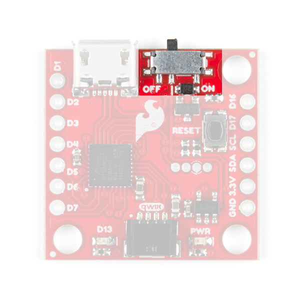
Supplying Power and Power Switch
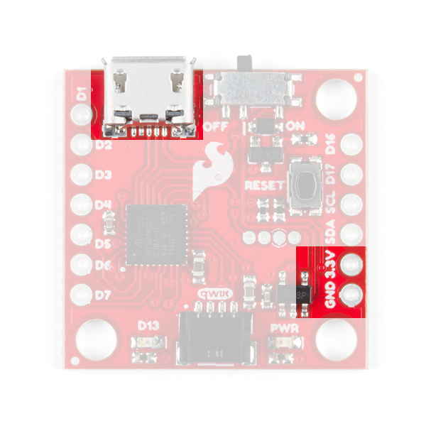
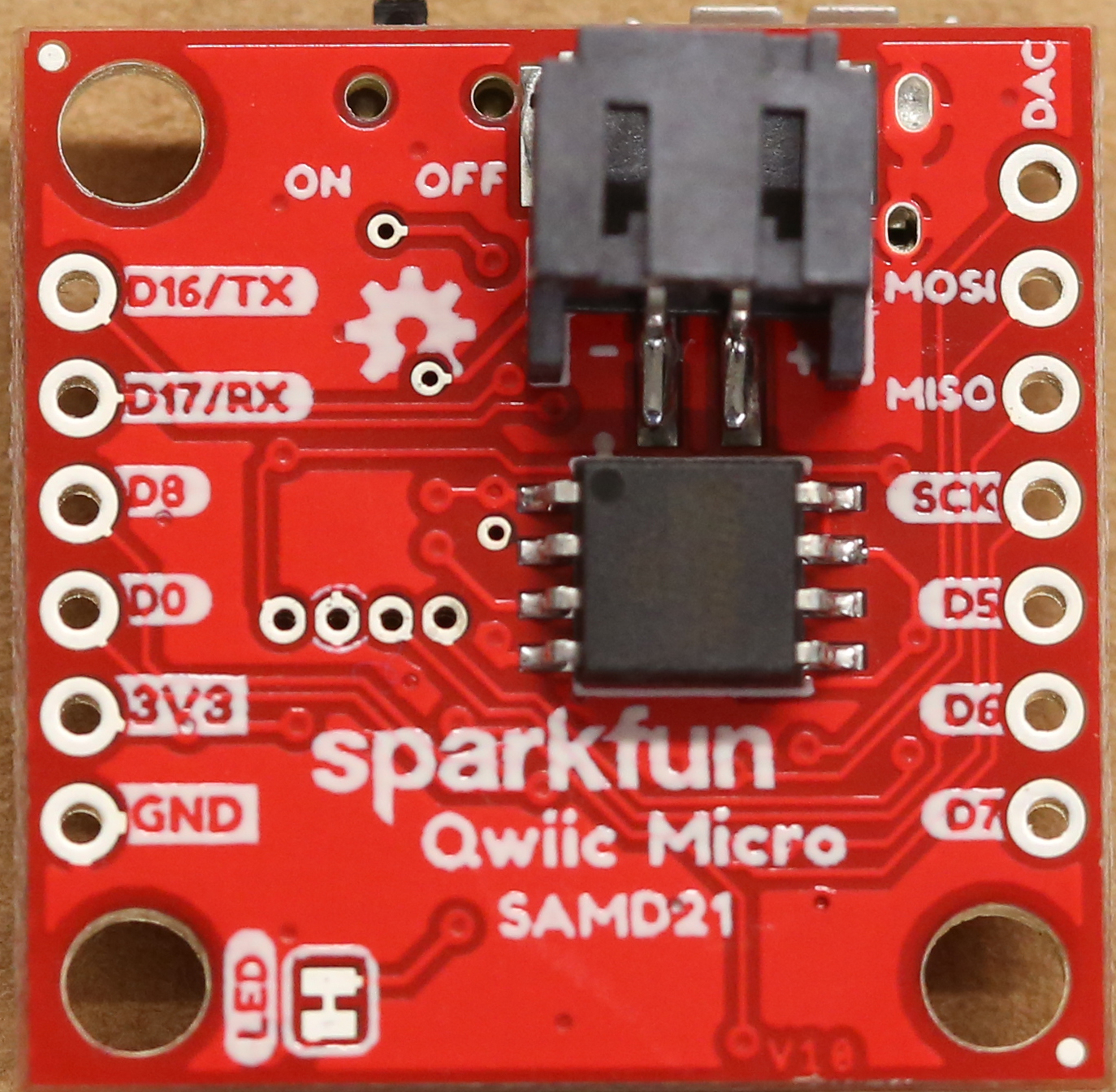
The SparkFun Qwiic Micro operates at 3.3 volts which makes it ideal for the Qwiic eco-system. Power can be supplied to the SparkFun Qwiic Micro through micro-USB. It is also possible to supply power through the through holes labeled 3V3 and GND located in the lower right hand section of the board.
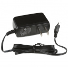
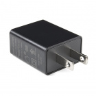
Additionally, we've provided pads for an SMD LiPo battery connector if you have it, see the Optional Circuitry section below. The micro-USB connector should work with one of the many USB phone-charging cables you have lying around, or one of our micro-USB cables. Below is a list of micro-USB options that SparkFun offers.

The power switch on the SparkFun Qwiic Micro controls turns it on and off when put into the on and off position respectively.
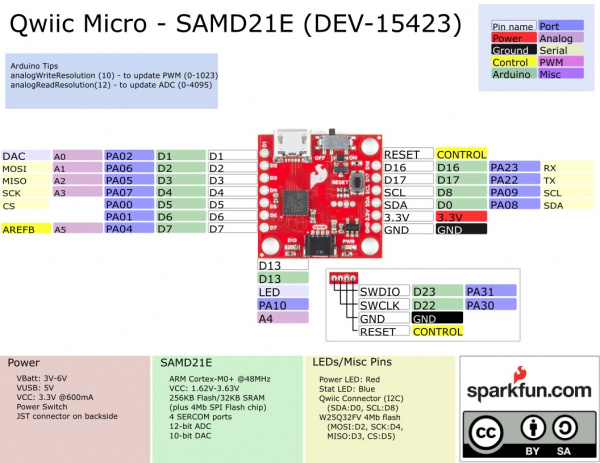
Pin Mapping
⚡ 3.3V Logic Levels! When you start interfacing with the SAMD21's I/O pins using external sensors and other components, keep in mind that each I/O will produce, at most, 3.3V for a high-level output.
When configured as an input, the maximum input voltage for each I/O is 3.6V (VDD+0.3V). If you're interfacing the SAMD21 with 5V devices, you may need some level shifters in between.
The graphical datasheet for the SparkFun Qwiic Micro below, shows the complete functionality of each pin; which pins are analog, digital, where SERCOM ports are located, and which data buses are available. All PWM-capable pins except the DAC are capable of PWM output. The DAC pin provides a true 10-bit analog output. In Example: Analog Input and Output, there are steps on how to take full advantage of this feature.
Qwiic Connector
On the opposite edge of the SparkFun Qwiic Micro is a Qwiic connector.
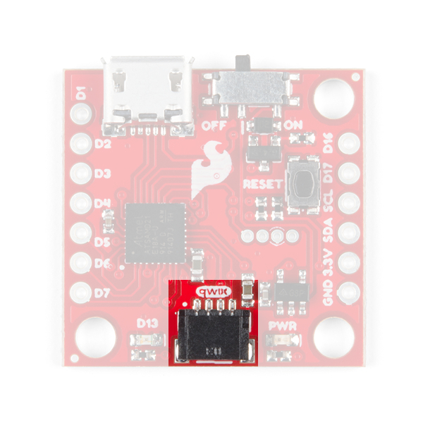
If you're not familar with the Qwiic Ecosystem, the short of it is that we have integrated Qwiic Connectors on many sensors and development boards that allow for quick (get it?) I2C connections through cables rather than soldering. It's an extremely useful tool. Check out the banner below for more information.
LEDs
The SparkFun Qwiic Micro has a red power LED that has become emblematic of our Qwiic eco-system and indicates power is being supplied to the board and that the power switch is in the ON position. Additionally, there is a stat LED that is attached to pin D13 and is labeled D13.
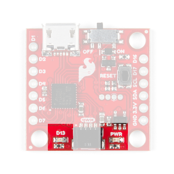
If you want to minimize the current draw of your Qwiic Micro or just don't like the power LED we've provided a jumper on the underside to disconnect it; see Jumper section below.
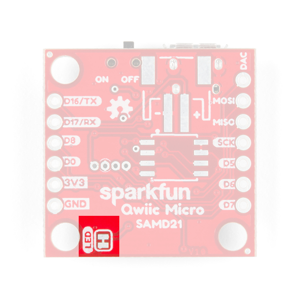
Jumper
On the underside of the SparkFun Qwiic Micro just below the power LED we've provided a jumper to disconnect the power LED to help keep the current draw of the microcontroller low. Simply take a hobby knife and cut the trace in between the two pads to sever its' connection. Simply re-solder this jumper to reconnect it. If you need some instructions for working with jumper pads then check out our tutorial.
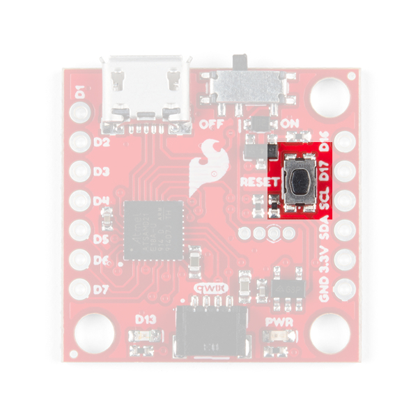
Reset Button
On the topside of the SparkFun Qwiic Micro is a reset button which resets the board when pressed. If you find yourself with a botched Circuit Python installation, or a sketch that has left your board inoperable, then you can tap this button twice to re-enter bootloader mode. You'll know you've done it correctly when the D13 Stat LED is dimming and brightening in a breathing pattern.
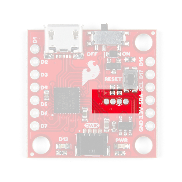
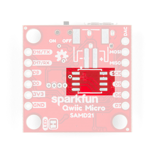
Programming Header
There is a small four pin programming header exposed on both the top and bottom side of the SparkFun Qwiic Micro. This header breaks out the following pins for SWD programming:
 |
 |
| Pins from left to right. | |
|---|---|
| TOP | BOTTOM |
| SWDIO | RESET |
| SWCLK | GND |
| GND | SWCLK |
| RESET | SWDIO |
Programming through this header would allow you to put a different bootloader on the chip, or to configure the SAMD21's flexible SERCOM ports to add another I2C port for example. You can check out this guide to see how this is done.
0Ω Resistor Used to Help Program an AVR Chip via Test Pads
Optional Circuitry
LiPo Battery
On the underside we've included empty pads for a few optional items. First in the upper right is a space for a LiPo Battery Connector. You'll need to solder connector if you decide to power your project though this connector.

We provide a number of LiPo battery options when you're ready to integrate the SparkFun Qwiic Micro into your project.

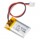


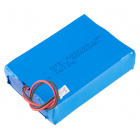

Lithium Ion Battery - 1Ah
PRT-13813Optional Flash Memory Chip
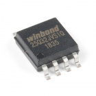
Just below that is a space for a flash memory chip.
If you want to add extra memory to the SparkFun Qwiic Micro than you can solder an 8 pin SOIC to these pads. The 4MB flash chip from Winbond: the W25Q32FV which works with the very useful Arduino Library SPI Memory. Check out Example 4: Flash Memory to see how to use an external flash with the SparkFun Qwiic Micro. In addition we've provided CircuitPython firmware for the SparkFun Qwiic Micro that can use this memory as well.
When everything is soldered onto the bottom, it will look like this:
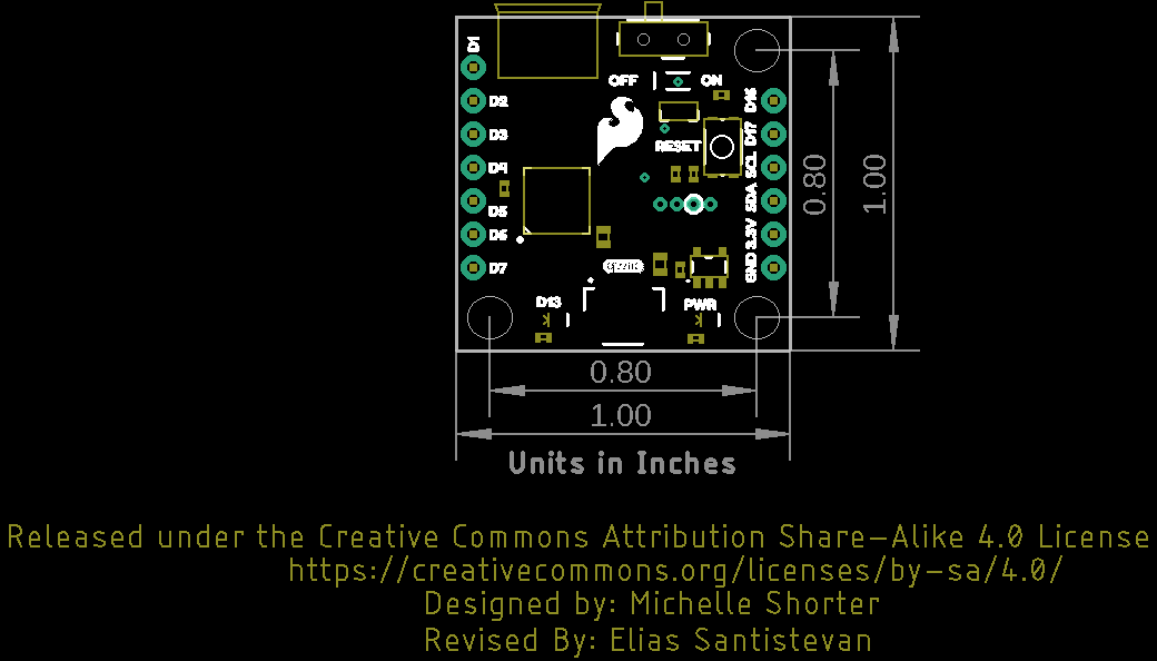
Board Dimensions
The board utilizes the standard 1.0"x1.0" square like a majority of the Qwiic enabled sensors. Due to the size of the board, there are three mounting holes on each corner of the board. Grab some standoffs and screws to make a Qwiic sensing tower of boards!