Installing a Bootloader on the MicroView
 jimblom
 Introduction
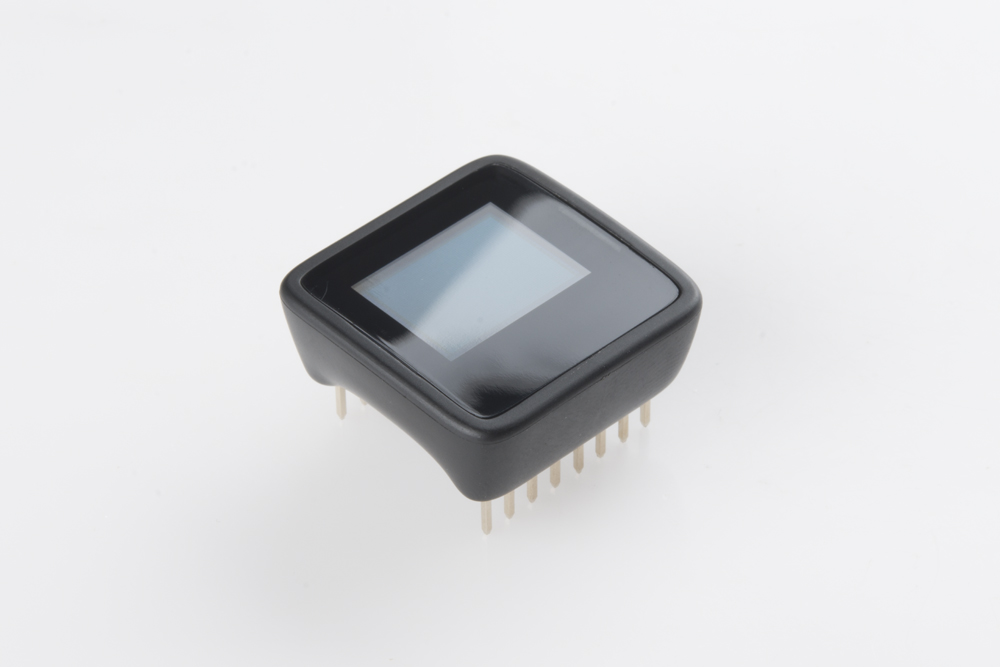
The MicroView. Such a cool concept! An Arduino, with a built-in display, fully enclosed in a beautiful, ergonomic case. Use it to create small video games, wearable electronics, or to simply explore electronics and programming. But as cool as the MicroView is, if you can't reprogram it, it's not much more than an annoyingly repetitive demo.
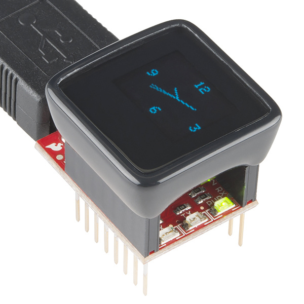
In August 2014, we (unknowingly at the time) sent out nearly 2000 MicroViews without bootloaders. Void of a bootloader, the MicroView is essentially un-programmable -- that exciting Arduino platform becomes a glorified paperweight.
A bootloader is a small piece of firmware, living inside a microcontroller's memory, which can write to the remaining program memory of that microcontroller. Bootloaders usually allow for easier, less expensive means for updating the program memory on a processor. Instead of specialized tools to program the device, more generic, commonly available components can be used.
One of the reasons Arduinos, like the MicroView, are so popular is because they all have a serial bootloader built into them. Instead of using an external piece of specialized hardware – in this case an AVR ISP (in-system programmer) – to program the processor, a more commonly available serial port can be used. In the case of the MicroView, that's the MicroView USB Programmer, which converts the ubiquitously available USB to serial.
If you've received a defective unit, first of all: we're so sorry! We're shipping replacements as fast as we can build them, you'll be getting one soon. In the mean time, this is a great opportunity to learn a new skill.
In this tutorial, we'll walk you through every step involved in loading a bootloader onto the MicroView: disassembling the enclosure, wiring up an assortment of programmers in a variety of ways, programming the bootloader, and testing it out.
Gathering the Tools
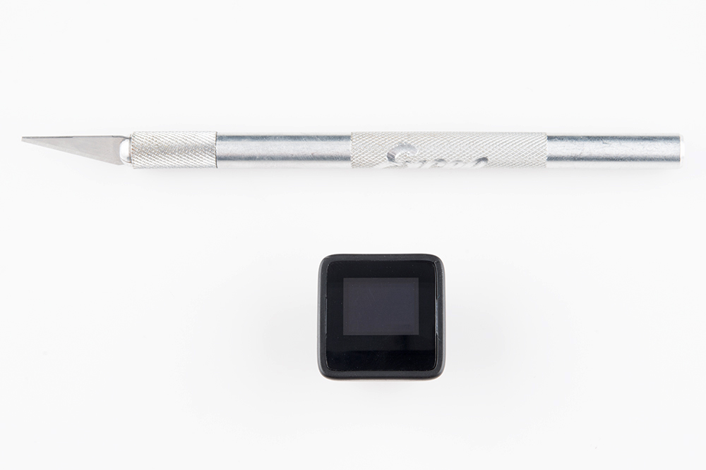
Before you get going, there are a few tools you'll need to gather: something to pry open the MicroView, a method for connecting to the small vias, and an AVR programmer. There are many options for each of those tools, we'll list a few in the sections below.
For those short on one tool or another, we've created the MicroView Bootloading Kit, which includes everything you'll need to follow along with this tutorial.
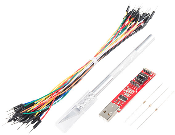
The kit is an especially great deal if you need an AVR programmer -- the price for the kit (which includes a knife, jumpers, and resistors) is the same as the programmer itself.
An Opener
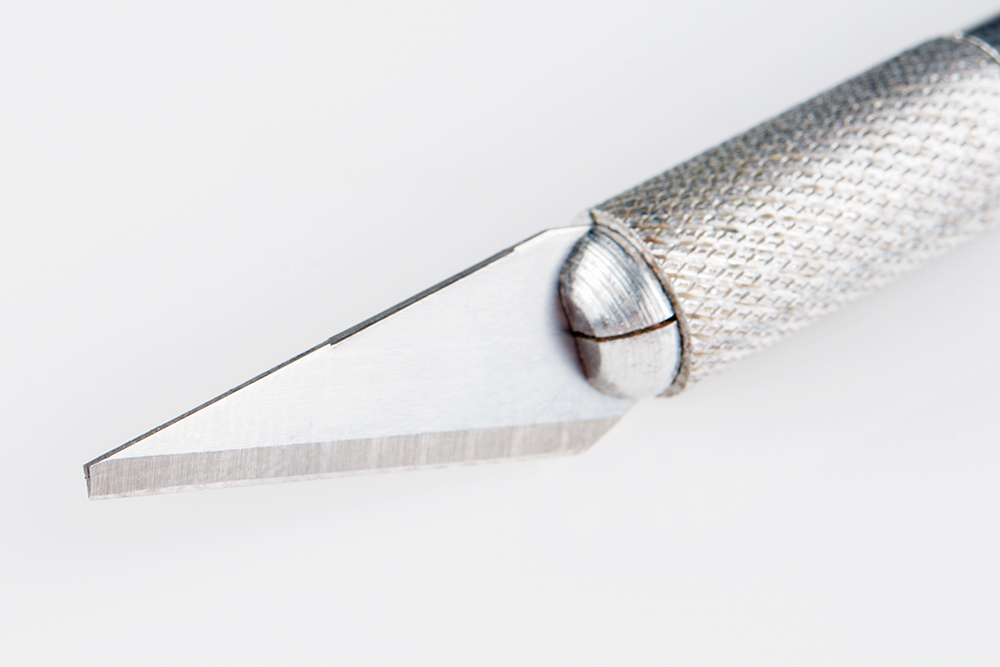
A thin, flat, rigid-ish tool is required to separate the MicroView's shell from the lens covering it. This can be a spudger, hobby knife, or a thin flathead screwdriver (the smallest bit in our Pocket Screwdriver works).


The knife has a lower potential for scratching your MicroView's shell, but the tip will also probably break on your first pry attempt. Use a more veteran, dulled blade if you can. Or, better yet, sacrifice a blade and break the sharp end of the tip off.
A Programmer
There are a multitude of tools that can perform the task of reprogramming a MicroView over ISP. There are boards built for the task, like the Tiny AVR Programmer, STK500 USB Programmer, or the AVR Pocket Programmer.
Pocket AVR Programmer
PGM-09825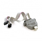
STK500 Compatible USB Programmer
PGM-08702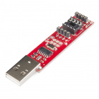
Tiny AVR Programmer
PGM-11801Even if you don't have a dedicated AVR programmer, you might have a programmer and not even know it! Most Arduino's can be programmed to replicate an AVR Programmer. If you have an Arduino Uno, RedBoard, Pro, or, really, any ATmega328P-based Arduino, you're already good-to-go.
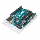
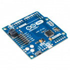
Arduino Pro 328 - 5V/16MHz
DEV-10915
By loading the ArduinoISP sketch onto your Arduino, it'll transform into a USB AVR programmer. Arduinos programming Arduinos: madness!
Jumper Wires
To connect between your Programmer and the MicroView, you'll need six, individual male-to-male jumper wires. Most M/M jumpers will do, including the standard or premium sets.


You can even use solid-core wire if you'd like.
The Arduino IDE
There are a handful of software tools that can be used to reprogram AVRs. The easiest program, and the one we recommend, is the good ol' Arduino IDE. Arduino has a built-in tool, which allows you to burn a bootloader into any of its many boards, it makes programming a bootloader as easy as two clicks.
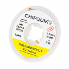
(Optional, Recommended) Solder Tools or Thin-Gauge PTH Resistors
The hardest part of this whole process is connecting your programmer to three of the MicroView's tiny ISP pins. Due to space restrictions they're broken out to a trio of small, exposed vias.

If you apply enough steady pressure, you can complete those three connections without soldering or connecting anything else. Be warned, though, that it'll take a few tries to get right; if you're low on patience, frustration might brew.
If you'd like to avoid soldering to your MicroView, one trick is to plug through-hole, 0Ω (or, at least, very low resistance) resistors into the MicroView's three ISP vias. The trick is finding resistors with thin enough leads. The 0Ω resistors on our Resistor Kit work perfectly for this task, but watch out, many other resistors -- especially those rated for ¼W and above -- have too-thick leads.
(There are all sorts of other, clever ways to connect into those vias. For example, you can poke them with sewing needles. You just need something with a diameter under about 0.015" that conducts electricity.)
Instead of jamming resistors into the vias, if you have soldering tools handy, you can make the programming process a lot smoother by temporarily soldering a jumper wire to the test pin -- creating a reliable electrical connection between MicroView and programmer. A simple iron, and some solder is all you should need.


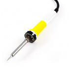
Soldering Iron - 30W (EU, 230VAC)
TOL-11650Solder wick might help when you get to disconnecting the wires and cleaning up.
Identifying a Defective MV
Before we trip into the rabbit hole, we should at least make sure your MicroView is actually missing its bootloader. If you haven't already, follow along with the MicroView Getting Started Guide. That will walk you through driver installation, and plugging in the MicroView.
Testing With Arduino
Alternatively, you can try uploading a sketch in the Arduino IDE. Load up any of the examples included with the MicroView Library. Double-check that your Serial Port is set correctly, and the Board is set to "Arduino Uno". Then click Upload.
During the upload, you should see the yellow "RX" LED on your MicroView USB Programmer blink. If all you see is three quick blinks, that's an early warning sign that the bootloader is missing. After waiting a few more seconds, an error should be produced in the Arduino IDE's console. If you get something like this:
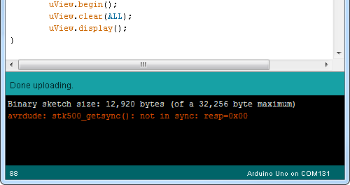
...or any of these errors:
avrdude: stk500_recv(): programmer is not responding

avrdude: ser_recv(): programmer is not responding

avrdude: stk500_getsync(): not in sync: resp=0x00

avrdude: stk500_getsync() attempt 10 of 10: not in sync: resp=0x00
...your MicroView probably doesn't have a bootloader. Time for surgery.
(Carefully) Opening the Case
The AVR ISP programming interface requires six pins: VCC, GND, RST, MOSI, MISO, and SCK. VCC (power), GND (ground), and RST (reset) are all broken somewhere along the MicroView's readily available pair of 8-pin headers. Unfortunately, the three SPI signals are not broken out to the headers, they're tucked away, inside the enclosure, broken out to three unmasked vias. To expose these pins, you'll have to remove the Microview's covering lens and lift the display up.
Grab your spudger, hobby knife or small, flathead screwdriver. And find a flat, steady surface to do the deed.
If you're using a sharp-edged hobby knife, you may want to grab a pair of pliers and snap off a small chunk of the tip to get a more blunt, flat edge.
The lens cover is held in place by two securing notches on the left and right sides of the enclosure. Try to expose as much of a gap on one side as you can, by sliding the lens to either the left or right. You may be able to see one of the securing notches.
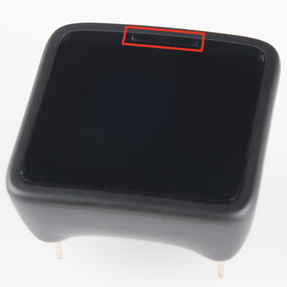
Insert your opener somewhere between that notch and the bottom of the cover. You should be able to push it in about 2mm, before a beveled edge inside the enclosure gets in the way. Be gentle, but try to push in as far as you can to get more leverage.
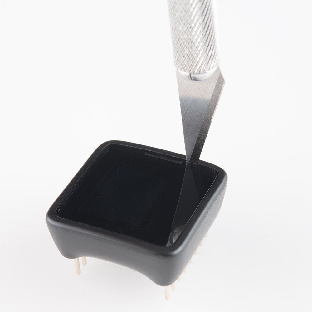
Then pry up the cover by tilting the opener towards the outside of the MicroView.
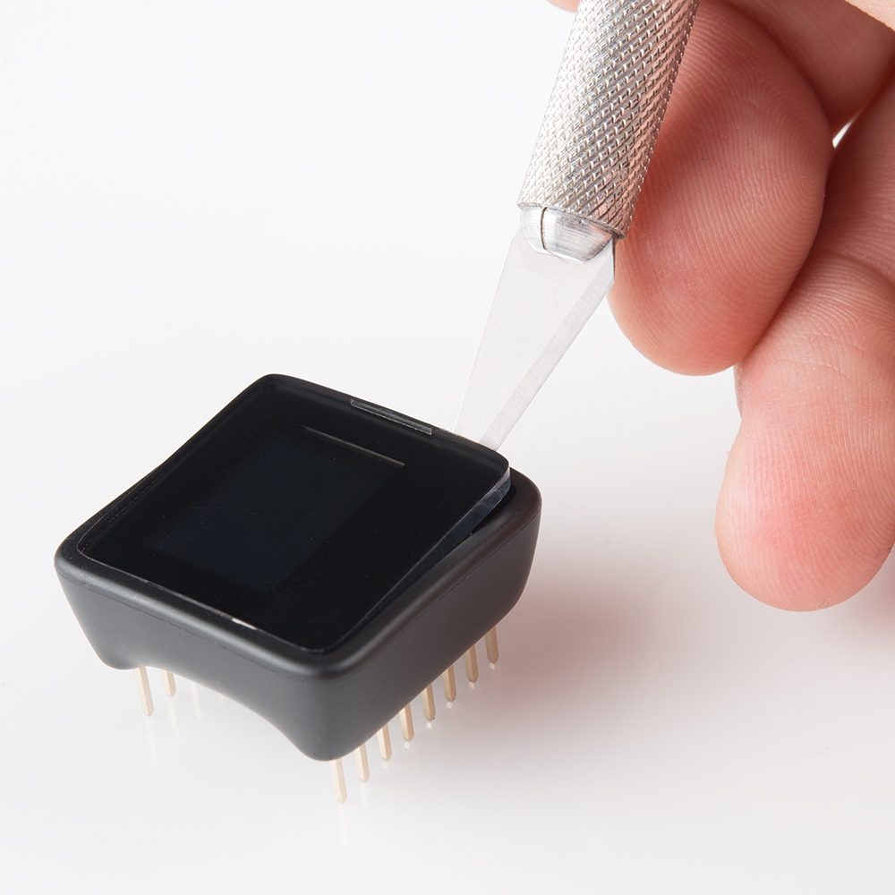
Once the edge of the screen has popped off, grab it with your fingers and pull it off.
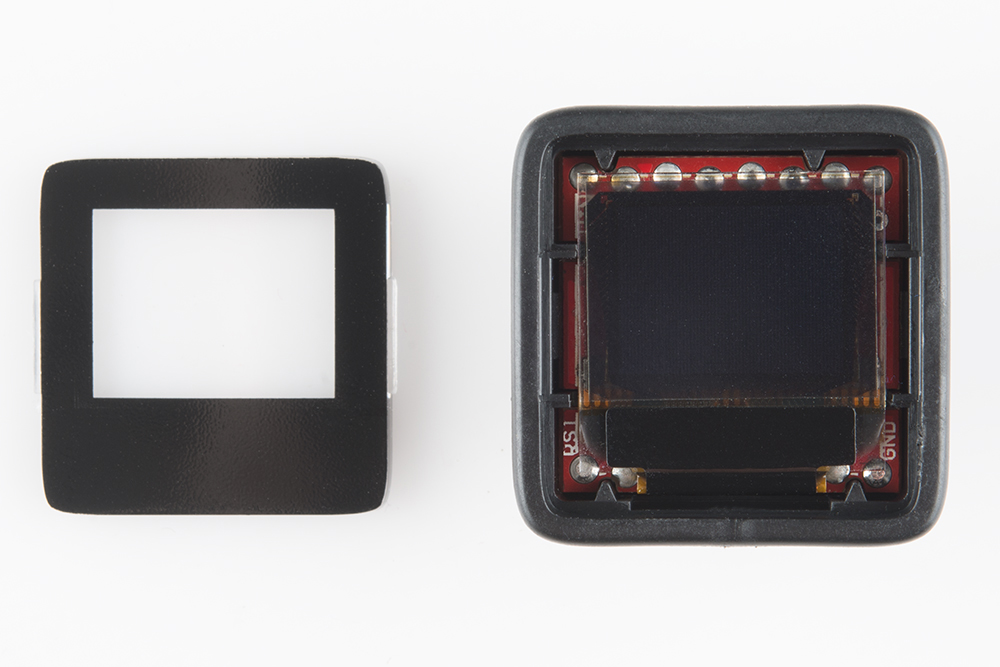
The exposed pins for MISO, MOSI, and SCK are just under the display. To access them, very carefully pry the OLED up. The OLED is connected to the PCB via a thin, black connector; it's fragile, take great care not to place any extra stress on it.
Those three, small unmasked vias, labeled "11", "12", and "13", are what we're after!
Wiring the Programmer
As evidenced by our list of devices in the "Programmer" part of the "Gathering the Tools" section, there is no shortage of boards that can program a bootloader. In this section we'll demonstrate how to hook up a few of the most common programming tools.
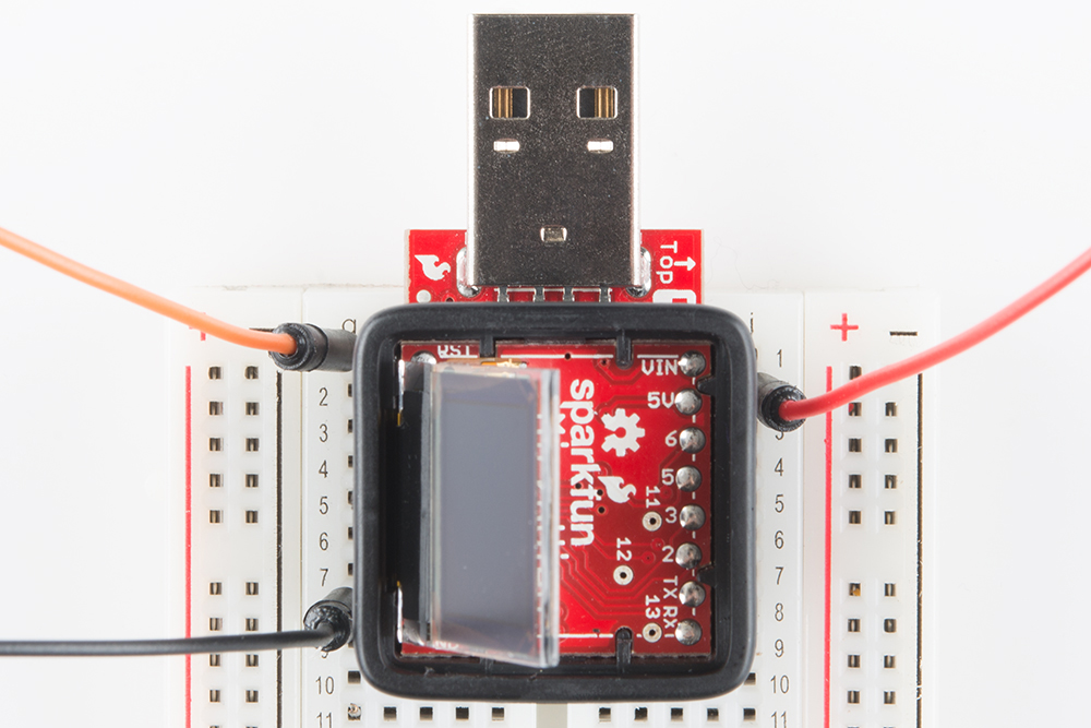
For each, we'll have to wire up six signals: VCC, GND, Reset, MOSI, MISO, and SCK. We'll use the following color coded wires for the six signals:
| Signal Name | MicroView Pin | Wire Color |
|---|---|---|
| VCC | 5V | Red |
| GND | GND | Black |
| Reset | RST | Orange |
| MOSI | 11 | Green |
| MISO | 12 | Blue |
| SCK | 13 | Yellow |
We will repeat the hookup for each programmer, click below if you want to skip to a particular device:
- An AVR Pocket Programmer (or any dedicated AVR Programmer with a 2x3 ISP cable)
- A Tiny AVR Programmer
- An Arduino equipped with the ArduinoISP sketch.
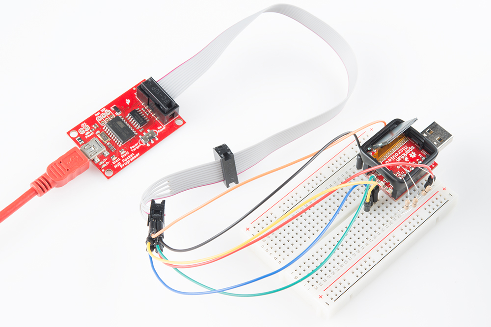
Connecting to an AVR ISP 2x3 Cable
Before connecting the programmer to your MicroView, you may need to install drivers. If you're using the AVR Pocket Programmer, follow along with our Pocket AVR Programmer Hookup Guide for guidance.
Most AVR development boards, like the Arduino Uno, break out a 2x3 header specifically geared towards (re)programming via ISP. This header matches up to a standardized 2x3 ISP footprint (or a larger 2x5 variant) with the following pinout:
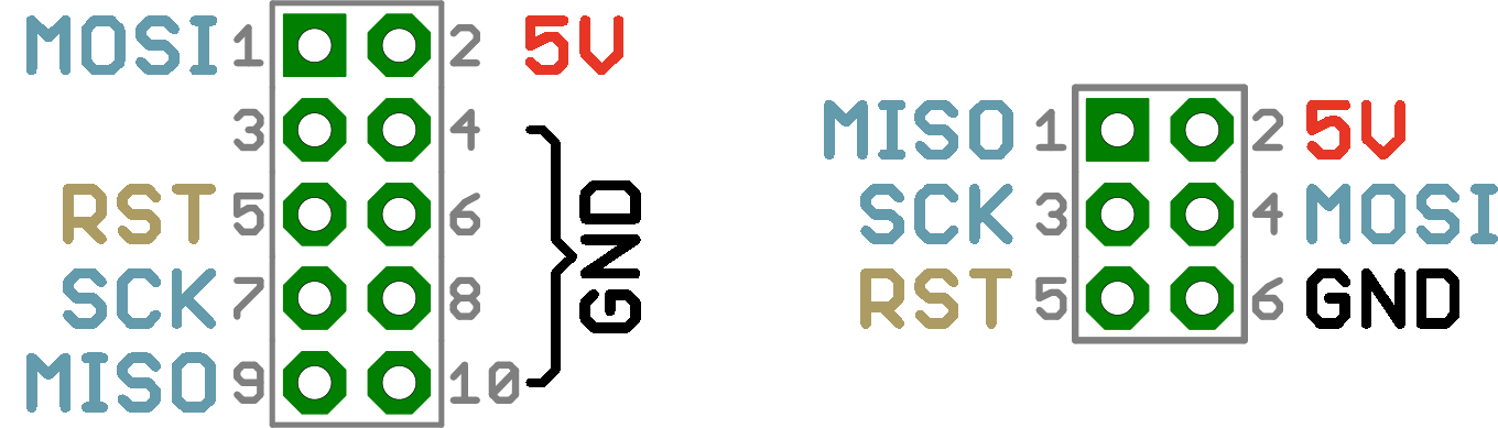
Those pinouts are a top-view of the connector as it would be on the PCB. If you're plugging wires into the cable, you need to flip that image over the horizontal. Here's how those signals are routed on the cable connector:
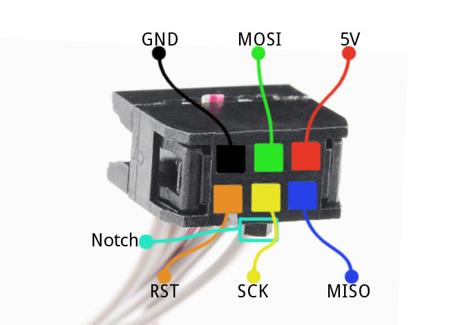
Note that the notch in the cable indicates the pin-1 side of the footprint.
Unfortunately, the MicroView PCB wasn't big enough to fit the whole standardized ISP header, but, once you've removed the cover, all of the pins you need are exposed in one way or another.
Plug your six jumper cables straight into the 2x3 connector. Use color-coded wires if you can. Here's where each ISP pin goes (note the notch, indicating the pin 1 side):
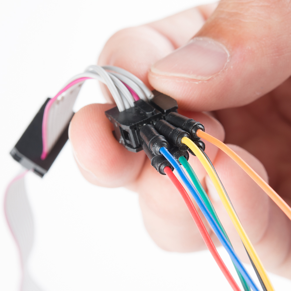
Then skip to the Wiring to the MicroView section to complete the wiring.
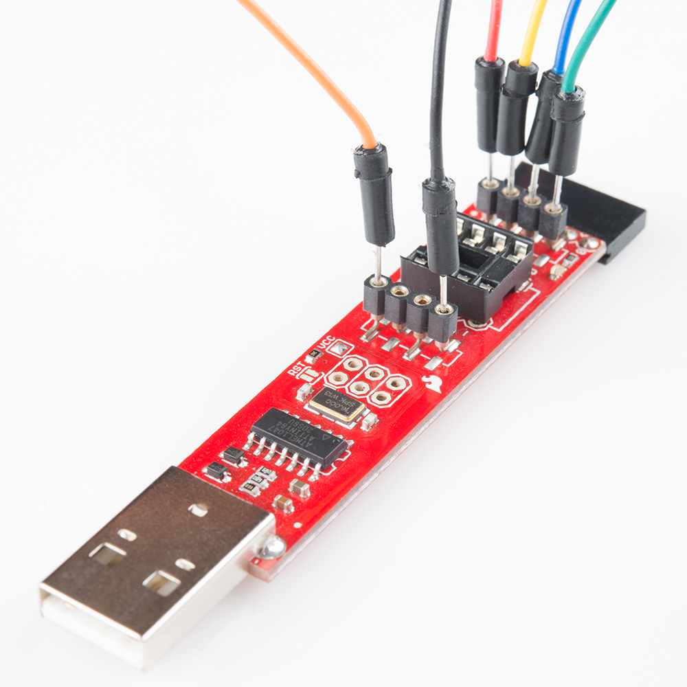
Connecting to the Tiny AVR Programmer
The Tiny AVR Programmer is a tool built for programming ATtiny85's, but it's more multi-purpose than that! It can program any AVR. If you're approaching this task with the Tiny AVR Programmer, make sure you've read through our Tiny AVR Programmer Hookup Guide -- at least through the driver installation section.
The Tiny AVR Programmer doesn't mate to a standard 2x3 connector, the pins we'll need are all broken out to both the 8-pin DIP socket and the two 4-pin machine-pin connectors. Here's what's what:
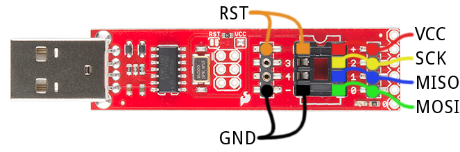
Insert your wires. Color code them if you can.
Then proceed to the Wiring to the MicroView section.
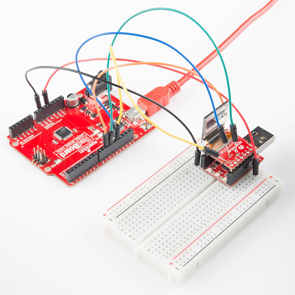
Connecting to an ArduinoISP
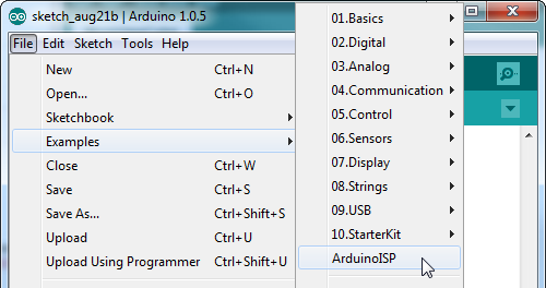
Just about any, old Arduino can be turned into an AVR ISP. All you need is the right sketch: ArduinoISP, which is included by default with the Arduino IDE. Open the sketch by going to File > Examples > ArduinoISP. Then upload it to your Arduino, which fortunately already has a bootloader!
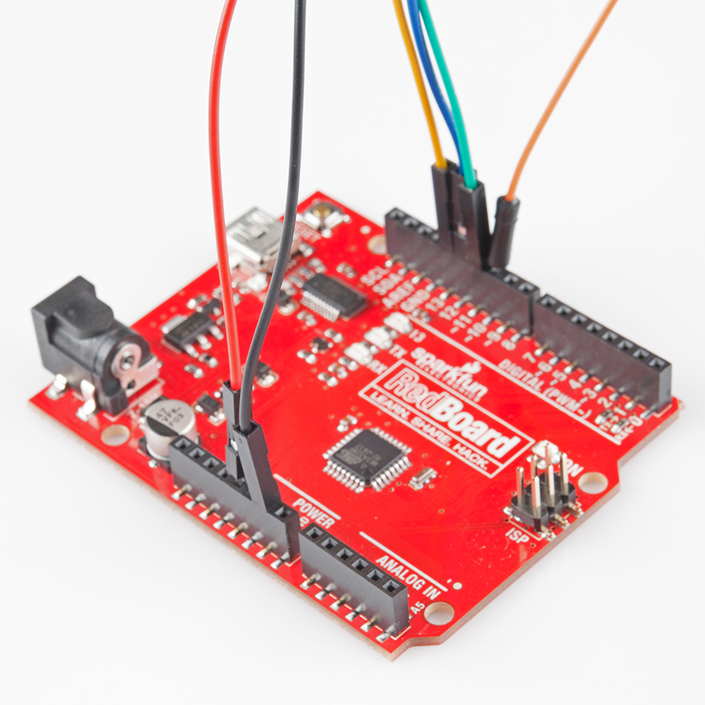
The ArduinoISP sketch uses Arduino pins 10, 11, 12, and 13 as RST, MOSI, MISO, and SCK, respectively. If you're using an Arduino Uno, you may also need to connect a 10µF capacitor between the reset pin and ground. Here's how it'll be wired up to the MicroView:

Note that the ArduinoISP sketch does provide for some simple debugging by assigning LEDs to pins 7, 8, and 9. They're completely optional, but can make tracking down errors a bit easier. An LED on pin 9 will indicate a "heartbeat", 8 will blink if there's an error, and pin 7 will indicate that programming is in process.
Use some color-coded jumpers to wire it up, like this:
Then proceed to the next section, to wire it up to the MicroView.
Wiring the MicroView
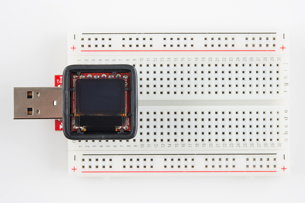
You've wired up to the programmer, that's (the easier) half of the wiring. Now to wire up the MicroView. To begin, plug your MicroView into the USB Programmer, then plug the Programmer into a breadboard.
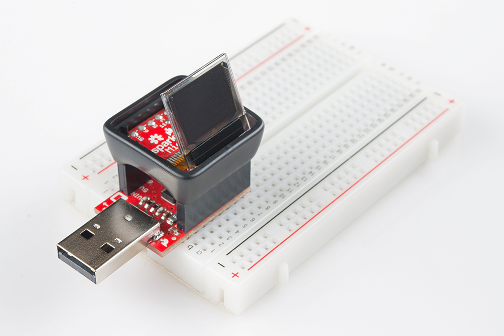
The breadboard will be useful as both a wire tie-in point and as a steadying tool.
Power and Reset
The VCC, GND, and RST pins are, fortunately, all broken out on the Microview.
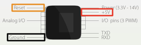
Wiring those to your programmer is as simple as plugging some wires into a breadboard.
This is a good time to think about how you're going to power the MicroView as it's being programmed. Some programmers -- including the ArduinoISP, Tiny AVR Programmer, and AVR Pocket Programmer -- can power the MicroView by themselves. Other programmers (like more official Atmel AVR ISPs) require the MicroView be powered externally. If you need to externally power the MicroView, plug the USB Programmer into your computer. But, if you're going to power the MicroView from your AVR programmer, leave your MicroView's USB Programmer unplugged.
Connecting to MOSI, MISO, and SCK (11, 12, and 13)
Now the hard part. We need to connect the three SPI lines as follows:
| Programmer Pin | MicroView Pin |
|---|---|
| MOSI (D11) | 11 |
| MISO (D12) | 12 |
| SCK (D13) | 13 |
Having gone through this process more than a few times, here are three possible methods we've gotten to work. Click to skip to the respective section:
- Soldering wires to vias -- With soldering tools and a careful hand, you can solder jumper wires directly to the vias. This is the most reliable method, but also requires the most tools -- not recommended for a beginning solderer.
- Inserting 0Ω Resistors -- If you have 0Ω "jumper" resistors (like those in our Resistor Kit), and their legs are skinny enough, you can plug them into the MicroView's vias. This is a relatively reliable, temporary solution.
- Holding wires in place -- Short of any other option, you can try holding all three wires in place, as you burn the bootloader. This method works, but requires some patience and steady hands.
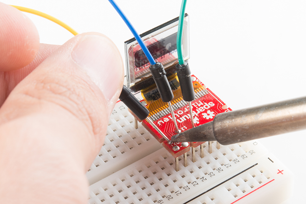
Soldering the Wires
If you have a soldering iron handy, we recommend connecting the jumper wires to the vias with a small dab of solder. If you're taking a soldering iron to your MV, you may want to lift the entire board out of the enclosure to avoid burning the edges. Press down on the MicroView's enclosure, using the table to push the header pins up, it'll take a steady amount of force to unseat the PCB from its retaining clips.
Apply a dab of solder to the vias.
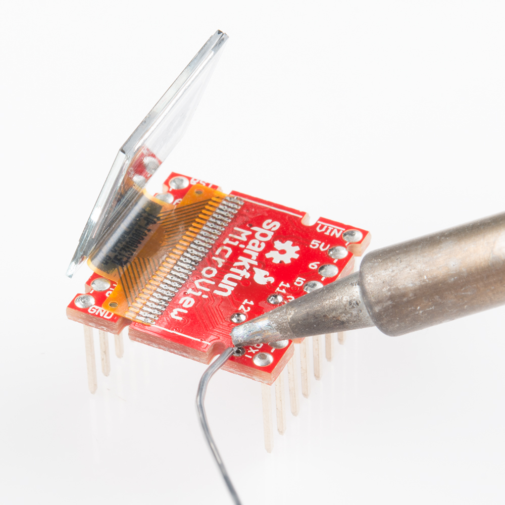
Then heat the solder dab back up and fuse an end of the jumper wire to it. Repeat that process for each of the three vias.
After the wire is soldered, take care to not to let it pull on the MicroView too hard. You'll risk lifting the via and its copper of the board entirely (then you'll be left to soldering to the ATmega328P's pins).
Plug those wires into the correct port of your programmer:
Then skip to the next section.
Connecting via 0Ω Resistors (Or Thin Solid Wires)
If you're lacking for soldering tools, or just want to avoid altering your MicroView, see if you can grab three 0Ω (or at the very least very small, <50Ω) resistors. Those included in our Resistor Kit work perfectly. You may have to dig around to find a resistor with thin enough terminations, they'll need to be less than about 0.015" to fit in the MicroView's vias.
Plug each of the resistors into a different via on the MicroView, then plug the other end of the resistor into a unique row on the breadboard.
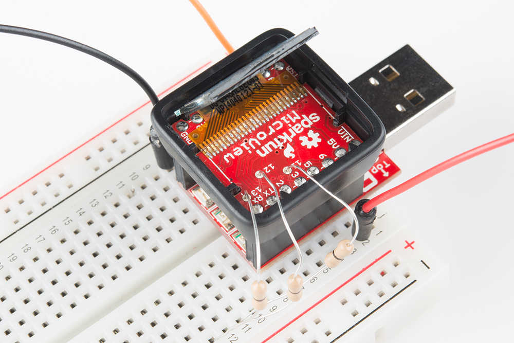
Then route each of the programmer's SPI pins to the appropriate row in the breadboard. You may need to just slightly bend the resistor at the point that it hits the via -- just enough for it to make an electrical contact.
We're teetering on the edge of reliability here, but this option is still worlds better than the next...
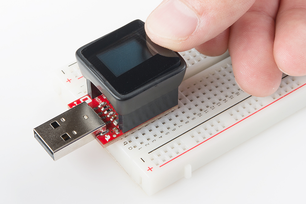
"Push-Connecting" the Wires
If you don't have either soldering tools or low-impedance resistors, you better have dexterity, a steady hand, and patience. You can "poke" each of the three jumper wires into their respective vias, creating just enough of an electrical connection. We really recommend asking a buddy to help you out here, because while one hand is busy holding the wires in place, the other will have to be on your computer mouse, clicking through menus.
Before actually pushing the wires into place, click over to the next page and get fully prepared to program your bootloader. Once your mouse cursor is hovering over "Burn Bootloder" in the Arduino IDE, then you can start fussing with push-connecting your jumper wires.
There are no real tricks to this. Begin by pushing a wire into pin 13. Once that's steady continue on to pin 12, holding both jumpers between thumb and forefinger. Finally add pin 11.
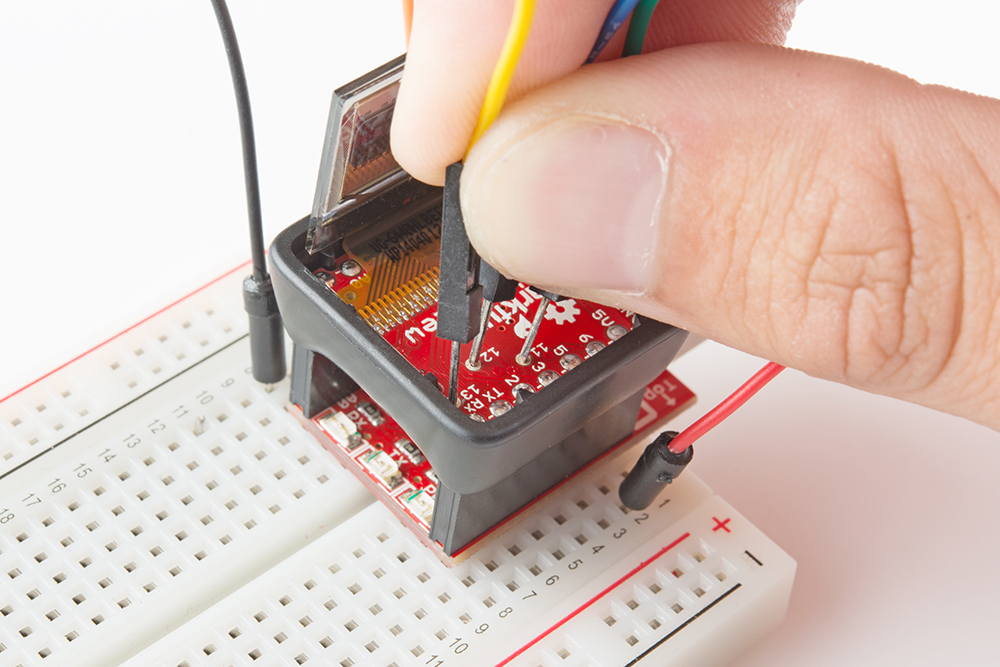
Then quickly start programming! You'll have to hold them in place for about 30 seconds.
Burning the Bootloader
This section will cover two readily available software tools that can be used to interact with your AVR ISP to burn a bootloader onto your MicroView. Pick one that best suits your comfort level:
- Arduino IDE -- If you have the Arduino IDE installed, this is an easy GUI-based way to program your bootloader.
- AVRDUDE (Command Line Utility -- AVRDUDE is a command line utility which can be invoked to program AVR's. This method is recommended only for advanced users. Unknown factors, like file locations and environment variables, come into play here, so you may have to slightly alter our example commands to get them to work on your computer.
The Arduino method won't give you instant gratification after burning the bootloader. The MicroView Demo code isn't included with the bootloader, so you'll have to upload it separately, after burning the bootloader. With AVRDUDE you can pinpoint the HEX file you want to upload, so you can upload the combined bootloader/MicroView Demo file and instantly discover if your MicroView is back to 100%.
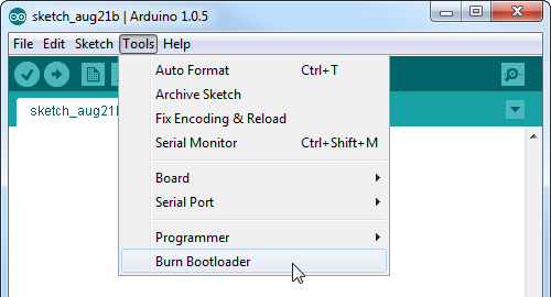
Burning the Bootloader in the Arduino IDE
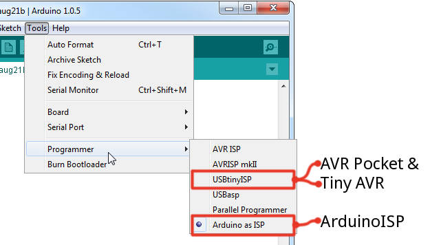
Open up Arduino, then go up to Tools > Programmer. Select the programmer that matches what you're planning on using. For the programmers we've discussed in this tutorial, that will either be USBTinyISP or Arduino as ISP.
If you're using an Arduino as the ISP, make sure the Serial Port is set to that Arduino's port number. If you've recently uploaded the ArduinoISP sketch to your Arduino, it's probably set correctly, but check!
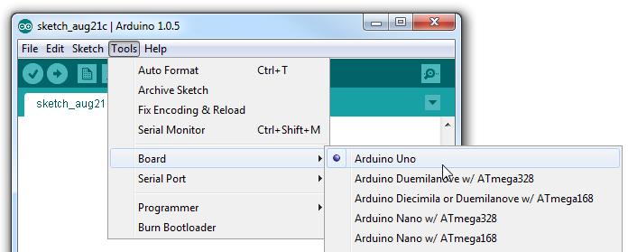
Finally, make sure the board is correctly set. This will determine which bootloader gets programmed onto your MicroView. It should be set to Arduino Uno.
That's all for the settings. Now, make sure your programmer is correctly connected to your MicroView, and go to Tools > Burn Bootloader, and enjoy the light show.
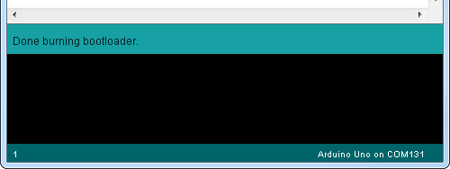
The bootloader burn process usually takes around 30 seconds. If your holding the jumper wires in place, hold steady! After the bootloader has been programmed, you should see a surprisingly brief "Done burning bootloader" message above the console.
If you get an error, like avrdude: initialization failed, rc=-1, there's either an incorrect or missing connection. Double-check to make sure everything is connected correctly.
If you've gotten good news, continue on to the Testing and Closing section. The MicroView screen will be blank; during bootloader upload, the program that was on the MicroView was erased, so, for now, the MicroView doesn't have any sketches on it.
Programming via AVRDUDE and Command Line
Behind the scenes, Arduino uses AVRDUDE to communicate with and command your programmer. Instead of using Arduino as a front end, you can invoke AVRDUDE from the command line. You'll need to have AVRDUDE installed or existing on your computer somewhere (download AVRDUDE here).
You'll also need the (working) MicroView HEX file, click here to download the MicroView bootloader hex file, "MicroView_combined_8-19-14.hex". To make the example commands easier, we'll assume the hex file is in the same location as AVRDUDE.
If you have an AVR Pocket Programmer or Tiny AVR Programmer, a command like this will upload the bootloader to your Arduino.
avrdude -c usbtiny -p atmega328p -U flash:w:MicroView_combined_8-19-14.hex -U lock:w:0x0F:m
If you're using an Arduino as an ISP, use a command like below. You'll need to put your Arduino's COM port # in place of our placeholders (COMN for Windows or /dev/tty.usbmodemNNNN for Mac/Unix):
Windows: avrdude -p atmega328p -c avrisp -P COMN -b 19200 -v -e -U flash:w:MicroView_combined_8-19-14.hex -U lock:w:0x0F:m

Mac: avrdude -p atmega328p -c avrisp -P /dev/tty.usbmodemNNNN -b 19200 -v -e -U flash:w:MicroView_combined_8-19-14.hex -U lock:w:0x0F:m
After sending the command, your terminal will be swamped with writes, reads, and other messages until the entire bootloader has been programmed.
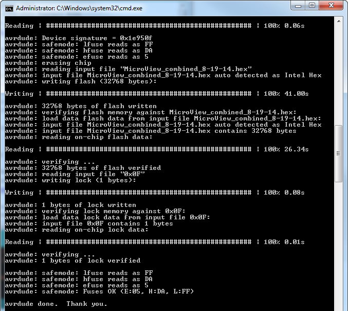
After AVRDUDE says it's done, the bootloader should be programmed. As an added bonus, this HEX file includes the MicroView demo -- once it's been programmed the display should light up and start cycling through patterns.
Testing and Closing
We're just about back to square one. Before closing the MicroView back up, it'd be best to test it out and make sure it's bootloader-programmable.
Disconnect your AVR programmer from the MicroView, plug the MicroView into your the MicroView USB Programmer (if it wasn't already), and plug your programmer into the computer.
Then repeat the Arduino programming process from the "Identifying" section. In the Arduino IDE, load up an example from the MicroView library, make sure the Serial Port and Board ("Arduino Uno") are set correctly in the Arduino IDE, and program away!
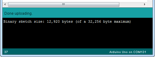
If you're greeted with a "Done uploading." message above the console, you've succeeded in reprogramming your MicroView! The MicroView Demo you've loaded should also start running. Program it again to make extra sure...
Closing the MicroView
If you soldered to any of the MicroView's vias, you'll first need to remove those jumpers from the board. Heat each joint up, and remove the wire one-by-one.
If you removed the MicroView PCB from the enclosure, put it back in. The MicroView PCB is keyed, so it should only go in one way, make sure the pairs of notches on the top and bottom of the board match up to the notches in the enclosure. Don't press down on the screen, lift it up and push the MicroView PCB into the enclosure. You should hear a snap as it clicks in, under two small clips on each side of the enclosure, which secure the PCB in place.
Next, fold the OLED back on top of the PCB. There are guides in the enclosure to hold the display in place. It should be seated just about flush with the enclosure notches on the sides and top of the display.
Before closing it up, gently wipe off the OLED to remove any fingerprints. You may also need to wipe off the bottom side of the enclosure lens as well.
Finally, close it up! The tabs of the enclosure are offset from the middle of the edge, they're closer to the inner-facing side of the lens. Slot in one tab of the enclosure lens, then press down on the opposite side to snap it in.
No one will ever know the difference!
Resources and Going Further
Now it's time for the fun part! Hopefully you're not already sick of the MicroView before you've gotten to play with it.
To get started with the MicroView, we recommend reading through the MicroView Hookup Guide:
MicroView Hookup Guide
If you have the SparkFun Inventor's Kit for MicroView, head over to the experiment guide to get started:
SparkFun Inventor's Kit for MicroView
To really take advantage of the MicroView, we recommend familiarizing yourself with the powerful MicroView Arduino Library. With it, you can draw anything from simple shapes -- pixels, lines, circles, and squares -- to text and bitmaps. The MicroView Hookup Guide will help you get started with the Library.