Pocket AVR Programmer Hookup Guide
 jimblom,
  bboyho
 Introduction
Do you need more control over your AVRs? Whether it's an ATmega328, ATmega32U4, ATtiny85, if it's an AVR there's a good chance the AVR Pocket Programmer can program it.

Pocket AVR Programmer
PGM-09825There are many reasons for programming your AVR via an in-system programmer (ISP). If your AVR doesn't have a bootloader on it, it's probably the only way to load code. Or maybe you want to overwrite the bootloader to squeeze out some extra flash space. Or maybe you want to poke at the fuse bits, to change the brown-out voltage. Or maybe you just want a faster and more reliable code upload.
Covered In This Tutorial
In this tutorial we will introduce you to all of the important aspects of the AVR Pocket Programmer. It's split into a series of sections, which cover:
- Board Overview -- A look at the hardware components that make up the AVR Pocket Programmer.
- Installing Drivers -- How to install the AVR Pocket Programmers on a Windows machine (Mac and Linux users can skip this page).
- Programming via Arduino -- How to use the ubiquitous "easy-mode" AVR IDE to upload sketches via the AVR Pocket Programmer.
- Using AVRDUDE via Command Line -- A more advanced, command-line-based approach to using the AVR Pocket Programmer.
- Troubleshooting -- A few troubleshooting tips for resolving some of the AVRDUDE errors that you may run into.
Required Materials
Most importantly, to follow along with this tutorial, you will need an AVR Pocket Programmer and an AVR to program. On top of that, a mini-B USB cable is required to connect the Programmer to your computer.
That microcontroller-to-be-programmed can be any AVR with 64K or less of flash. The ATmega328 on an Arduino Uno or RedBoard works perfectly, but the ATmega2560 of an Arduino Mega does not.
Beyond that, you may need something to interface the Programmer to your AVR. Here are some useful accessories, which might make the job easier:
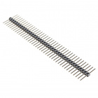
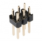
- Straight Male Headers -- If you have an AVR on a development board -- like an Arduino Pro -- the 2x3 (or 2x5) ISP header may not be populated. You can use straight male headers (also available in a long-pinned version) to make a temporary contact between ISP cable and your dev board. There is also a 2x3 pin version.
- ISP Pogo Adapter -- Like the headers, this ISP adapter is designed to provide a temporary electrical connection between adapter and AVR. This is a great, more reliable alternative to the headers.

Suggested Reading
Whether you're a beginner or experienced electronics enthusiast, the Pocket Programmer should be easy to get up-and-running. If you've programmed an Arduino before, you'll be well-prepared for the next step. Here are some tutorials we'd recommend reading before continuing on with this one:
- What is an Arduino? -- If you're unfamiliar with AVRs, check out this tutorial to learn about the most popular one of the lot.
- Installing Arduino -- Arduino isn't required to use the Programmer, but it can make things easier, especially if you still want to program your AVR using the Arduino libraries.
- Serial Peripheral Interface (SPI) -- The Pocket Programmer uses an SPI interface to send data to and from the AVR. Click this tutorial to learn the meanings behind "MOSI", "MISO", and "SCK".
Serial Peripheral Interface (SPI)
What is an Arduino?
Installing Arduino IDE
Board Overview
Before we get to using the AVR Pocket Programmer, let's quickly overview what components fill the board out:
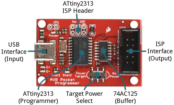
- USB Connector -- This is your data and power input to the Programmer. A mini-B USB cable plugs in here and connects your computer to the Programmer.
- 2x5 ISP Header -- This shrouded header mates with the included Programming Cable, and allows you to send the programming signals out to your AVR. It's polarized to make sure you can't plug anything in backwards.
- Power Target Switch -- Unlike a lot of ISP's out there, the AVR Pocket Programmer can deliver power to the AVR-to-be-programmed. Flick this switch to the "Power Target" side, to send 5V to the AVR. More on this below.
- ATtiny2313 -- This is the chip that works the programming magic. It converts between USB and SPI to turn commands from your computer into words and instructions to load into your AVR-to-be-programmed. Unless you want to customize the Tiny ISP firmware, you can leave this chip alone.
- The unpopulated ISP header, above the ATtiny2313, is broken out in case that chip needs to be programmed. It's mostly used in production by those who program the programmers.
- 74AC125 Buffer -- This chip helps to add some protection to the programmer by buffering the data-line outputs. Another IC to mostly ignore.
The board also includes a variety of LEDs to indicate power, status, and data transfers.
AVR ISP Pinouts
AVRs are programmed through an SPI interface. There are six unique signals required for communication between ISP and AVR: VCC, GND, Reset, MOSI, MISO, and SCK.
To route those signals between devices, there are two standardized connectors -- one 10-pin, 2x5 and another 6-pin, 2x3 connector:
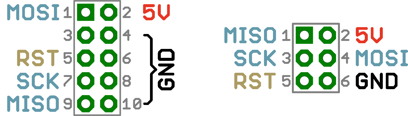
The AVR Pocket Programmer includes an on-board 2x5 connector, and the included AVR Programming Cable terminates with both 2x5 and 2x3 connectors.
Power Target Switch
If you're working with an AVR on a breadboard or a prototype, power may be hard to come by. The AVR Pocket Programmer allows you to route 5V out to your AVR. It can deliver upwards of 500mA before tripping the onboard PTC.
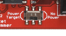
If the switch is in the Power Target position, it will route 5V out to your AVR. Otherwise, if the switch is pointing towards No Power, no signal will be connected to the 5V pin on the ISP connector.

Installing Drivers
Driver installation is required on Windows machines only. If you're using a Mac or Linux machine, you don't need to install drivers. Just plug the board in, and skip to the next section. Otherwise, follow along below as we overview the installation process.
There are two sets of instruction for driver installation on this page. The first is the easiest, quickest method, and should work for most everyone. The second installation process is only required if the first one fails -- it takes a more manual approach to the driver installation.
Automatically Install the Drivers with Zadig
To begin, plug the AVR Pocket Programmer into your computer. Upon initially connecting the board, Windows will try to automatically install the drivers. Some computers may be lucky, but most will turn up with a message notifying you that the driver install failed.
Click the link below to download the Zadig software and drivers:
Use your favorite unzipper to extract the ZIP file. Don't forget where you put the extracted folder!
After you've plugged the Pocket AVR Programmer into your computer and your machine has run through the process of checking for and failing to install drivers, proceed to the "zadig_v2.0.1.160" folder you just unzipped. Then Run zadig.exe software.
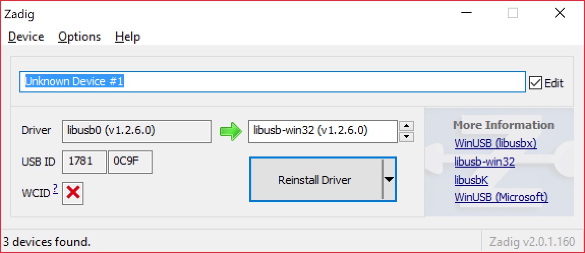
Zadig is a wonderful tool that can install the drivers on just about any Windows platform out there. Upon opening the program, you should be greeted with a window like this:
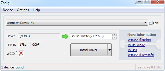
There are a few options to verify before installing the driver:
- Select the device -- The top dropbox controls which device you want to install the driver for. Hopefully you only have one option here, something like "Unknown Device #1". If you have more than one option, check your device manager to see if you can make sense of which is which (plugging and unplugging a device usually helps).
- Select the driver -- Click the arrows in this box until you happen upon libusb-win32 (vx.x.x.x), that's the driver we want to install.
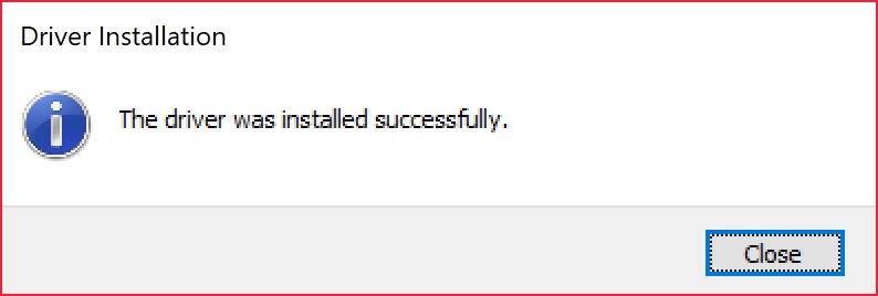
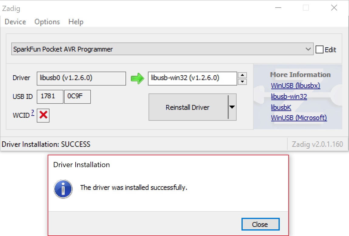
After verifying those two selections, click "Install Driver". The installation process can take a few minutes, but after you've watched the scroll bar zoom by countless times, you should be greeted with a "The driver was installed successfully" message.
Zadig Driver Installation Issues
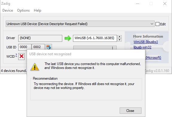
After installing the drivers, your computer may respond by indicating that the device was not installed correctly. Here are two methods of troubleshooting driver issues when installing with Zadig.📌 Troubleshooting Tip: In this case, the WinUSB drivers were selected instead of the libusb-win32 drivers. To remedy the issue, simply go through the guide again to reinstall the correct libusb-win32 drivers.
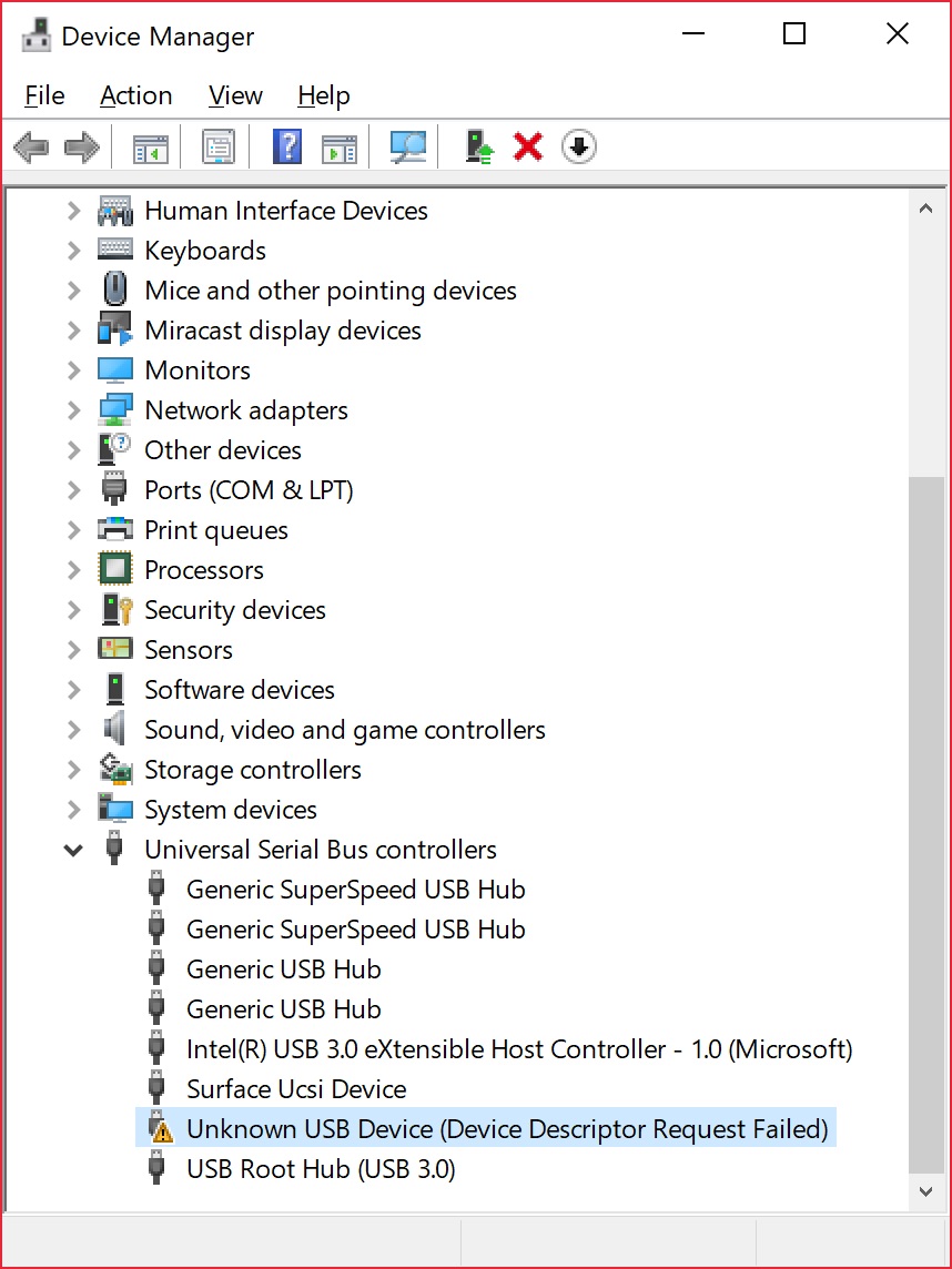
📌 Troubleshooting Tip: In other cases, it may also initialize somewhere in your device manager as an Unknown USB Device (Device Descriptor Request Failed) even if you installed the correct drivers:
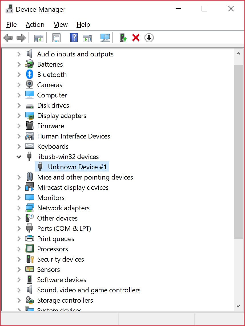
Try unplugging and replugging the Pocket AVR Programmer back into your USB port. Or switch out your mini-B USB cable for a known good. In some cases, your Pocket AVR Programmer may shows up under the libusb-win32 devices as an Unknown Device #1. As long as it shows up under libusb-win32 devices tree, you should be good to go!
Type in the name for your port. It can be "USBtiny" or in this case, "SparkFun Pocket AVR Programmer". Make sure that the correct driver is selected.
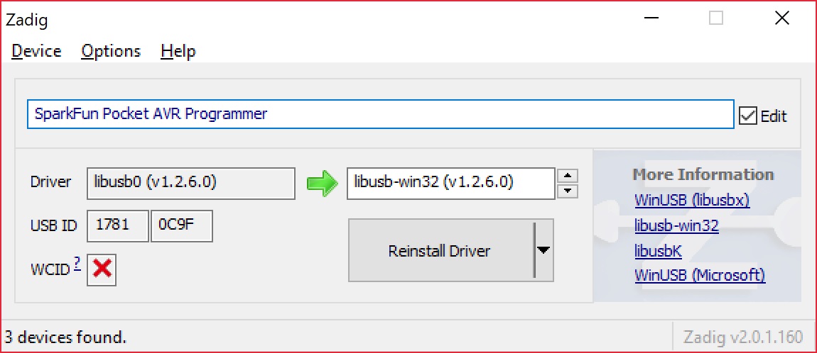
Click Reinstall Driver. The driver will reinstall and you should see the same message that indicates that the drivers were successfully installed. You may need to unplug and replug the programmer to your computer to give it a second to refresh again.
Open up your device manager and you should see the device renamed!

If you were successful, close out of the Zadig program and proceed to the next section!
If Zadig didn't work for you, check out the instructions below for help manually installing the drivers.
Manually Installing the libUSB Drivers
If, for some reason, Zadig didn't work for you. Read the instructions below to manually install the drivers. Click the link below to download the drivers:
Use your favorite unzipper to extract the ZIP file. Don't forget where you put the extracted folder!
After you've plugged in the Programmer, and Windows has failed to install the driver. Follow these steps to install the driver:
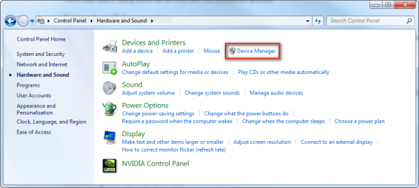
- Open the Device Manager -- There are a few routes to open up the device manager.
- You can go to the Control Panel, then click Hardware and Sound, then click Device Manager.
- Or, simply open the run tool (press Windows Key + R), and run
devmgmt.msc.
- You can go to the Control Panel, then click Hardware and Sound, then click Device Manager.
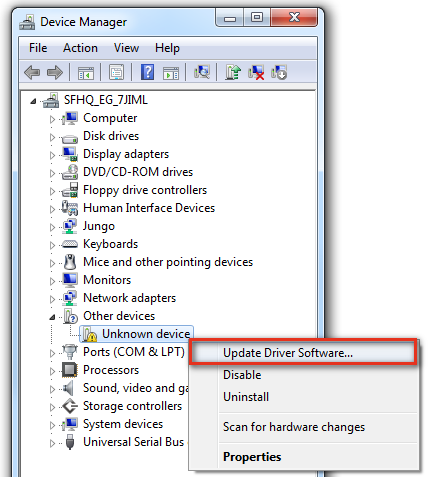
- In the Device Manager, you should see "Other devices > Unknown device". Right click "Unkown Device" and select Update Driver Software....
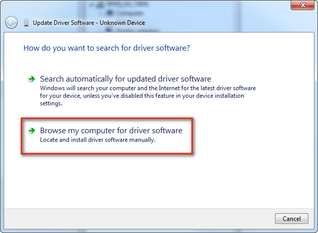
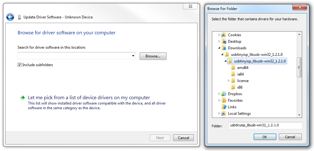
- Click Browse my computer for driver software in the "Update Diver Software - Unknown Device" window that pops up.
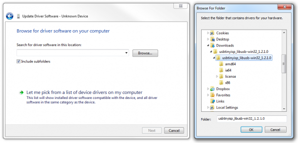
- Click "Browse..." and navigate to the "../usbtinyisp_libusb-win32_1.2.1.0" folder you just downloaded. Then click Next.
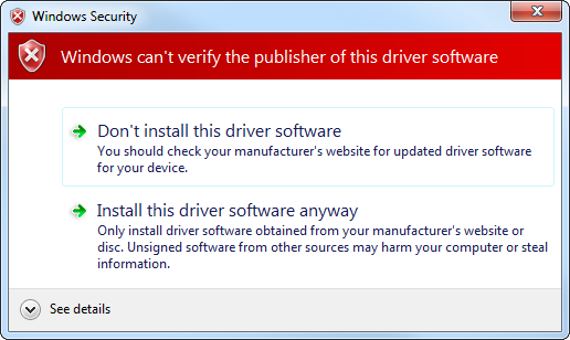
- Windows will begin installing the driver, and then immediately notify you that the driver isn't signed. Click Install this driver software anyway option, to proceed with the installation.
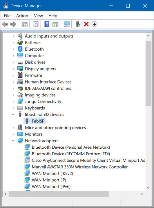
- After a few moments, the driver should successfully install. You'll be prompted with a "Windows has successfully updated your driver software" window. Close that, and you'll see a "USBtiny" entry populated in the Device Manager, under the "LibUSB-Win32 Devices" tree.

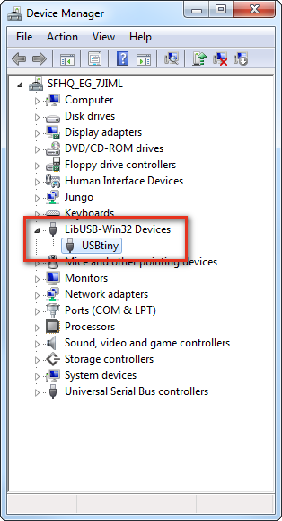
Congratulations! Proceed over to the next section, and we'll start using the Programmer!
Breathe easy now! Once you've installed the USBtiny drivers on your computer, you shouldn't ever have to do it again. Now it's time to program something!
Programming via Arduino
Arduino has a built-in tool that allows you to upload your sketch via a programmer instead of the serial bootloader. If you're just taking your first steps toward ISP-ing your Arduino-compatible AVR, this is a good place to start.
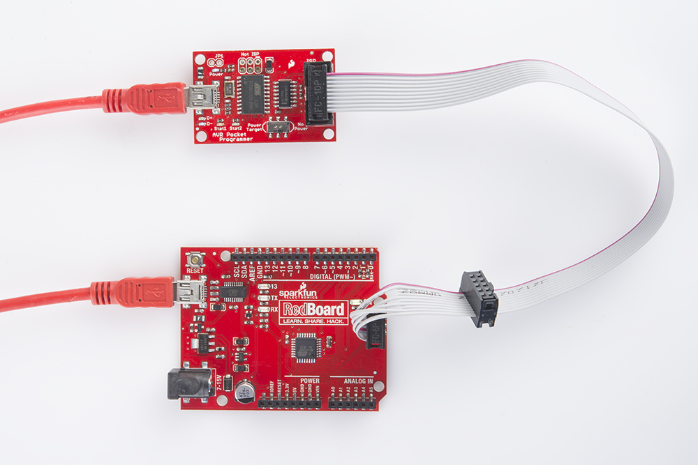
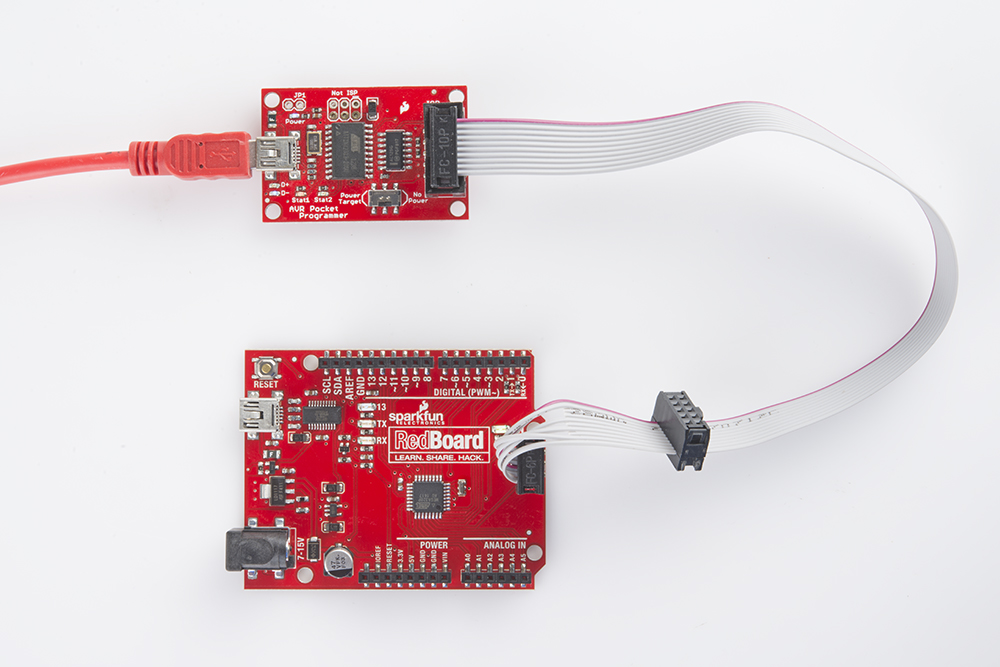
Connect the Programmer
First, let's connect the programmer to our Arduino. Most Arduinos break out the standardized 2x3 ISP header towards the edge of the board. Plug the 2x5-connector end of included programming cable into your AVR Pocket Programmer, then connect the other, 2x3 end into your Arduino.
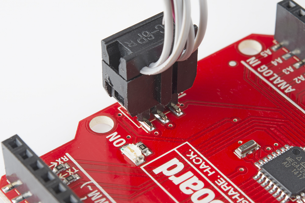
When connecting the programming cable to you Arduino, make sure you match up the polarity! The cable has a "notch" on one side of the plastic housing. This should point towards pin 1 of the Arduino's ISP header. Pin 1 is usually indicated by a stripe next to the hole or pin.
If your Arduino doesn't have the ISP pins populated, check out the bottom section of this page for some tips and tricks we've used through the years.
Powering Target
While connecting your programmer, double-check to make sure the "Power Target" switch is in the correct position. The programmer can power your Arduino alone! If you want it to handle that task, slide it over to the Power Target position.
Unplug your Arduino from USB if you're going to power it via the Programmer -- you don't want to create any ugly reverse current flows through your power sources.
Programming via Arduino
Now that the programmer is connected to your Arduino, open up the IDE. Then open an example sketch like Blink (File > Examples > 1.Basics > Blink).
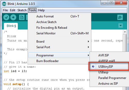
Before uploading, we need to tell Arduino which programmer we're using. Go up to Tools > Programmer and select USBtinyISP.
Also make sure you've set the "Board" option correctly! The serial port selection isn't required for uploading the sketch, but is still necessary if you're doing anything with the serial monitor.
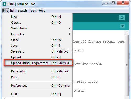
To upload the sketch using the programmer you selected, go to File > Upload Using Programmer. If you'll be doing this a lot, get used to pressing CTRL+SHIFT+U (COMMAND+SHIFT+U on Mac).
The Arduino will run through its normal process of compiling. After the sketch compiles, the Programmer will start lighting up blue everywhere -- the "D+" and "D-" LEDs will light up, and so will the "Stat2" LED. When the "Stat2" LED turns off, the upload will be finished. Check the status area of your Arduino IDE to verify that the sketch is "Done uploading."
If you've uploaded a sketch via the programmer, you've also wiped off the bootloader. If you ever want to put the serial bootloader back on your Arduino, check out the next section.
Programming a Bootloader
The Arduino IDE also has a feature built-in to allow you to (re-)upload a bootloader to the AVR. Here's how:
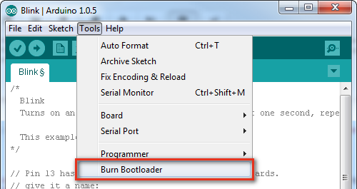
Make sure you've set the Board option correctly -- among other things, that will set which bootloader you'll be uploading. Then, simply navigate up to Tools > Burn Bootloader at the very bottom of the menu.
This process may take a minute-or-so. Not only will the bootloader be written into the flash of your AVR, the fuse bits (setting the clock speed, bootloader space, etc), and lock bits (barring the bootloader from overwriting itself) will also be (re)set.
The bootloader upload process is complete when the "Burning bootloader to I/O board (this may take a minute)..." message turns to "Done burning bootloader". It really does take a while -- it's not lying when it says it "may take a minute."
Pogo Pins or the Angled Header Press
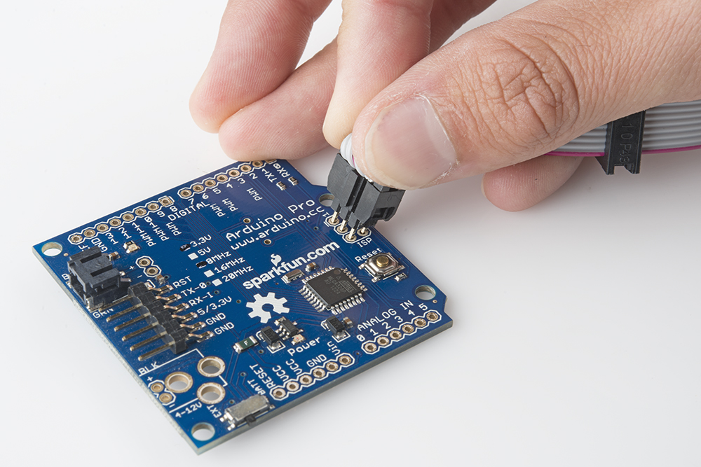
Most Arduino boards should have male pins populated on this 2x3 connector. If your board doesn't have pins shooting out of those holes, there are a few options.
You can solder a couple strips of 3 straight male headers in there, to get the best, most reliable connection. But if you want to avoid soldering, you can use those same headers (long headers work better for this), plugging the long end into the programming cable and pushing the short end into the empty holes, while angling them to make contact on all six pins.
Another solder-less option is to use the ISP Pogo Adapter, which will afford you a more reliable electrical connection.
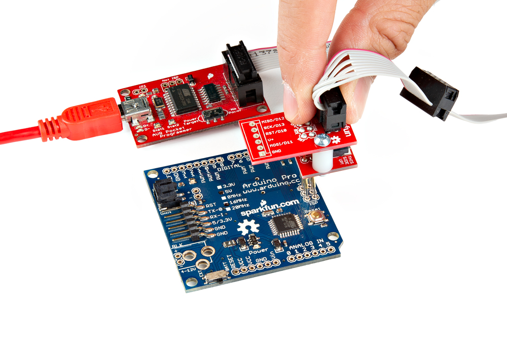
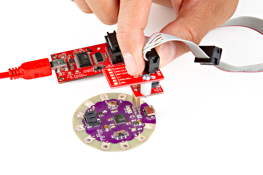
The ISP Pogo Adapter is also great for boards where the ISP programming pins are broken out to small test points such as the LilyPad Arduinos.
Both of these methods can be tricky -- you have to hold those pins steady while the code uploads to your Arduino -- but they're a good solderless, temporary option.
Using AVRDUDE via Command Line
If you're looking for more control over your AVR Pocket Programmer -- and the AVR it's connected to -- follow along below. We'll demonstrate how to use AVRDUDE, an open-source command line wonder-utility for reading, writing, and manipulating AVRs.
If you have Arduino, then you already have AVRDUDE installed -- it's the tool Arduino uses under the hood to upload sketches. If you need to install AVRDUDE separately, check out the documentation under AVRDUDE's downloads. The avrdude-doc-X.XX.pdf's (i.e. avrdude-doc-6.3.pdf) files are particularly useful when installing AVRDUDE for your operating system if you have issues using AVRDUDE commands in any directory via command line.
Sanity Check -- AVRDUDE Paths
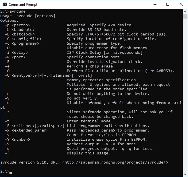
AVRDUDE is a command-line tool, so, in order to use it, you'll need to open up the "Command Prompt" (Windows) or "Terminal" (Mac/Linux). To make sure AVRDUDE is working it's good to do a little sanity check first. Open up the command line and type the following command.
language:bash
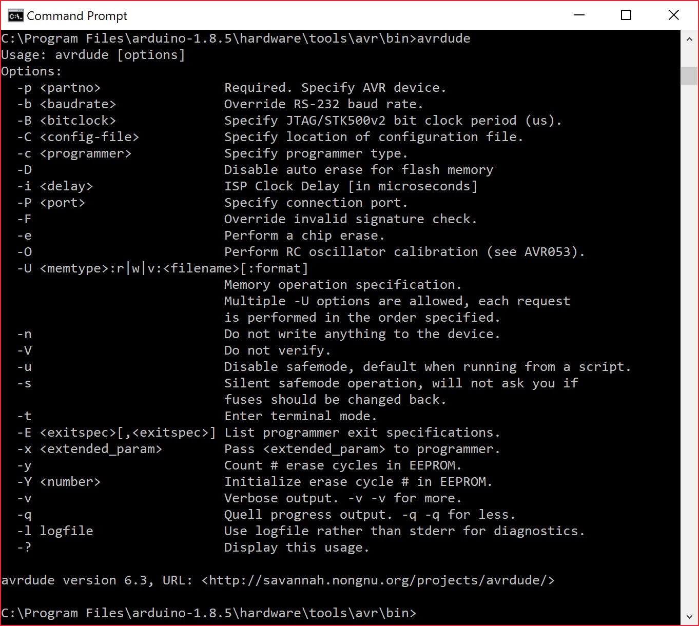
avrdude
You should see an output similar to the image below.
Sanity Check -- Device Signature Verification
To make sure AVRDUDE is working, and your AVR Pocket Programmer is connected correctly, it's good to do another little sanity check. Type this into your command prompt:
language:bash
avrdude -c usbtiny -p atmega328p
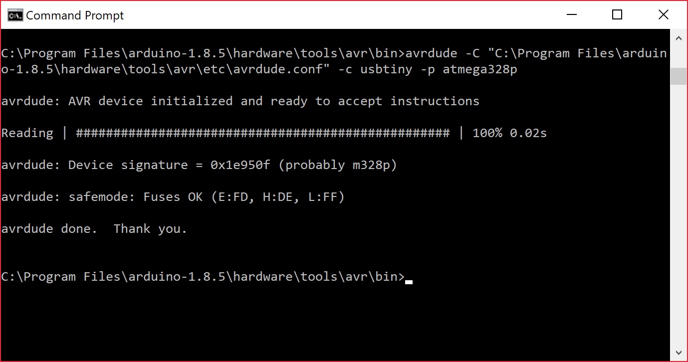
If everything is connected correctly, you should get a response like this:
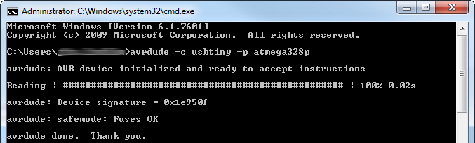
This basic command defines the programmer type you're using and the AVR it's talking to. AVRDUDE will attempt to read the Device Signature from your AVR, which is different for each AVR type out there. Every ATmega328P should have a device signature of 0x1E950F.
Flash Programming
Now that you've verified that everything is in working order, you can do all sorts of memory reading and writing with AVRDUDE. The main piece of memory you probably want to write is flash -- the non-volatile memory where the programs are stored.
This example will be using the blink.hex file as an example. Download the following files below. If you are using the blink.hex file, make sure that you unzip the folder and place it in the working directory.
This command will perform a basic write to flash using the HEX file.
language:bash
avrdude -c usbtiny -p atmega328p -U flash:w:blink.hex
Writing to flash will take a little longer than reading the signature bits. You'll see a text status bar scroll by as the device is read, written to, and verified.
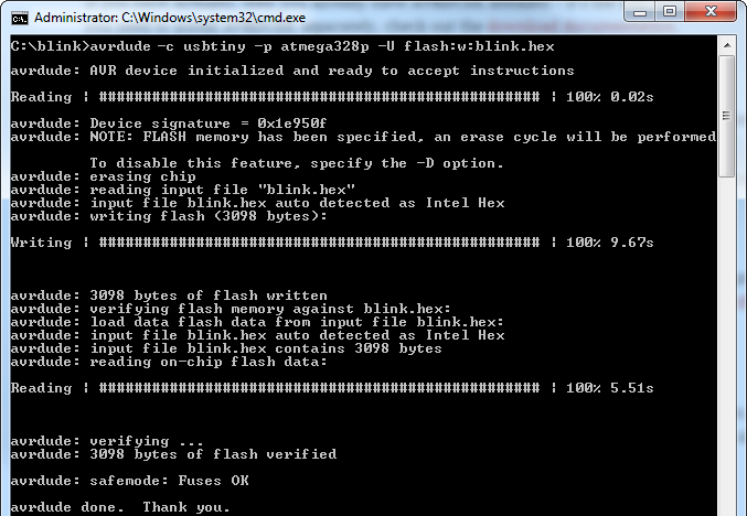
The -U option command handles all of the memory reads and writes. We tell it we want to work with flash memory, do a write with w, and then tell it the location of the hex file we want to write.
Invalid File FormatTo specify, you can by add an
:i to indicate that it is an Intel hex format:avrdude -c usbtiny -p atmega328p -U flash:w:blink.hex:iOr
:a to auto detect the format:avrdude -c usbtiny -p atmega328p -U flash:w:blink.hex:aFor more information, try checking the AVRDUDE's Online Documentation under the Option Description where it describes the command "
-U memtype:op:filename[:format]".Flash Reading
The -U command can also be used to read the memory contents of an AVR. A command like below, for example, will read the contents of your AVR and store them into a file called "mystery.hex".
language:bash
avrdude -c usbtiny -p atmega328p -U flash:r:mystery.hex:r
This is incredibly useful if you want to copy the contents of one Arduino to another. Or maybe you're a masochist, and you want to try reverse-engineering the mystery code in an AVR.
Reinstalling the RedBoard's Arduino Bootloader
Now that you have a hang of flashing hex files to your RedBoard, try reinstalling the bootloader with the following file. Download the file.
Navigate to the path where you downloaded the bootloader and enter the following command.
language:bash
avrdude -c usbtiny -p atmega328p -U flash:w:optiboot_atmega328_2012_with_1s_watchdog.hex
If all goes well, you should get a message indicating that it was written, verified, and finished uploading. You should get an output similar to the output below. In this case, the configuration file (i.e. avrdude.conf) and the bootloader (*.hex) were not located in the same working directory. Two additional commands were needed to specify where to look for the files. Additionally, the *.hex format needed to be autodetected when flashing the file by adding the :a.

Head back to the Arduino IDE, disconnect the USB cable from your programmer, and connect to the RedBoard's USB port to see if you can upload a simple blink.ino sketch back to the board via serial. Make sure to select the appropriate board definition and COM port before uploading. You should see a familiar message indicating that the Arduino IDE is "Done Uploading" when complete and the on-board LED begin to blink on pin 13.
Installing an Arduino Bootloader
Useful Options
Here are just a few last AVRDUDE tips and tricks before we turn you loose on the AVR world.
Specify Programmer and AVR Device
Two options required for using AVRDUDE are the programmer type and AVR device specification:
The programmer definition, assuming you're using the AVR Pocket Programmer, will be
-c usbtiny. If you need to use a different programmer check out this page and CTRL+F to "-c programmer-id".The AVR device type is defined with the
-poption. We've shown a few examples with the ATmega328P, but what if you're using an ATtiny85? In that case, you'll want to put-p t85instead. Check out the top of this page for an exhaustive list of compatible AVR device types.
Verbose Output
Adding one, or more -v's to your AVRDUDE command will enable various levels of verbosity to the action. This is handy if you need a summary of your configuration options, or an in-depth view into what data is being sent to your AVR.
There's plenty more where that came from. Check out the AVRDUDE Online Documentation under Option Descriptions for the entire list of commands.
Troubleshooting
Below are a few troubleshooting tips for resolving some of the AVRDUDE errors that you may run into.
AVRDUDE Not Recognized
If you are having issues getting a response from AVRDUDE, you may receive the following error. It's probably due to certain environmental variables or your computer settings preventing you from properly using AVRDUDE.
language:bash
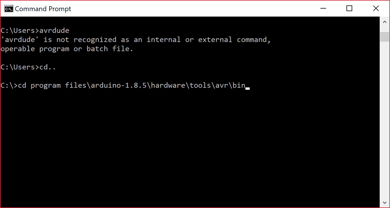
'avrdude' is not recognized as an internal or external command, operable program or batch file
The error output in the command line may look similar to the screenshot below.

One solution may be to try following the instructions provided by AVRDUDE to install it for your OS. For Windows, you could automatically install WinAVR 20100110 as explained briefly on page 35 of the AVRDUDE documents v6.3.
Otherwise, you can move to the Arduino IDE program folder where avrdude.exe is located. Try doing a search within the Arduino program folder to determine the path. Then navigate to the location where it is located using the cd.. and cd commands. In this case, Arduino IDE v1.8.5 was installed and located in the Program Files folder of my C:\ drive under ...\program files\arduino-1.8.5\hardware\tools\avr\bin. Type in the change directory commands to navigate to the proper location in the command line. From the screenshot of the error, I needed to move up the directory by using the following command.
language:bash
cd..
Then I needed to move into the Arduino's program folder that is located in the C:\ drive.
language:bash
cd programfiles\arduino1.8.5\hardware\tools\avr\bin
Your command line should look similar to the image below.
Once you are in the proper working directory, type in avrdude again. You should see an output similar to the image below.
Configuration File Not Found
If you are having trouble reading the AVR device signature to verify the device using the command avrdude -c usbtiny -p atmega328P; and you receive this error:
language:bash
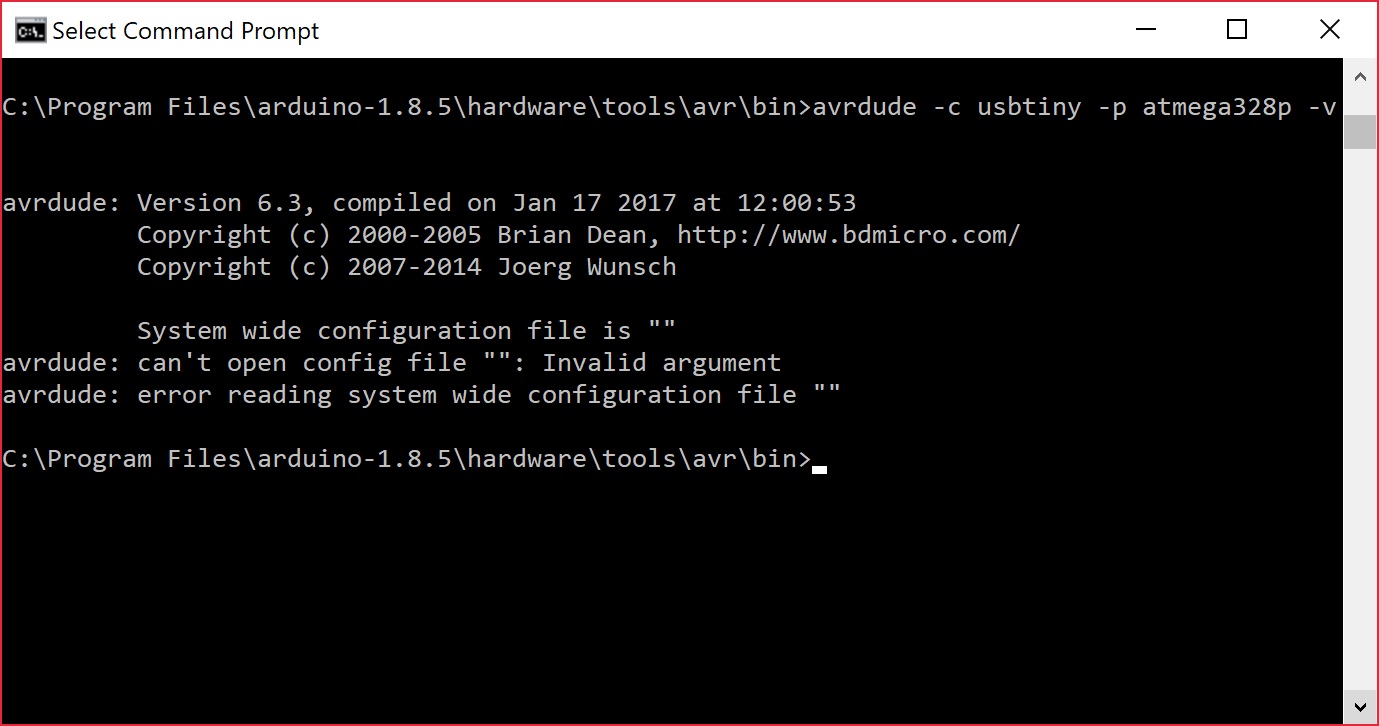
System wide configuration file is ""
avrdude: can't open config file "": Invalid argument
avrdude: error reading system wide configuration file ""
It's probably due to the way AVRDUDE was installed on a computer. In this case, AVRDUDE could not find the location of the avrdude.conf file. This is probably due to environmental variables or your computer settings preventing you from properly using AVRDUDE. If you remember from the earlier troubleshooting tip, AVRDUDE was located in the Arduino IDE program folder. While the working directory was correct, the avrdude.conf file was in a different folder as you can see from the image below on a Windows OS.
The easiest solution would be to adjust the environmental settings by automatically installing it for your OS as explained in the avrdude-docs (v6.3). For Windows, you could install WinAVR 20100110 as explained briefly on page 35 of the AVRDUDE documents v6.3.
Otherwise, you could use the -C command and provide the path in quotes ("...\avrdude.conf") where the avrdude.conf file is located. For the Arduino IDE v1.8.5, it was located in ...arduino-1.8.5\hardware\tools\avr\etc directory. Assuming that you have AVRDUDE in the working directory, the command should like similar to command below to read an ATmega328P.
language:bash
avrdude -C "C:\Program Files\arduino-1.8.5\hardware\tools\avr\etc\avrdude.conf" -c usbtiny -p atmega328p
A successful device signature read with the configuration file should look similar to the output below.
Driver Related Issues
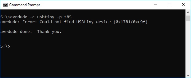
If you run AVRDUDE commands and receive this error below, the issue may be related to the drivers for the AVR Programmer whose device ID is 0x1781/0xc9f. Either the drivers are not installed or there is a driver conflict.
language:bash
avrdude: Error: Could not find USBtiny device (0x1781/0xc9f)
Drivers Not Installed
One solution is to ensure that the drivers are installed as explained earlier. You may also want to try another USB cable or unplugging/replugging the AVR programmer back into your COM port. The error output in the command line may look similar to the screenshot below.

Driver Conflicts
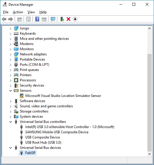
If you have installed the correct drivers as explained earlier, it's possible that there is a driver conflict. You'll receive the same error but the solution may not be as intuitive as you may think. The output in the screenshot below occurred when using the Tiny AVR Programmer to verify an ATtiny85's device signature. The drivers were installed correctly and had been working with the Pocket AVR Programmer. However, the Tiny AVR Programmer was still not recognized.
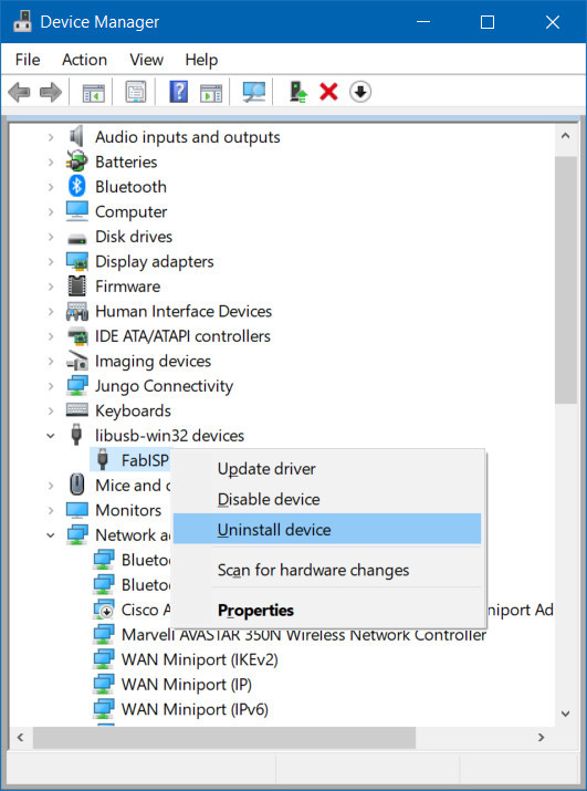
Opening up the device manager, the Tiny AVR Programmer showed up as a different driver (i.e. FabISP) and name as shown below.
The solution was to right click and delete the driver. Simply right click the COM port that it enumerated on and select "Uninstall device".
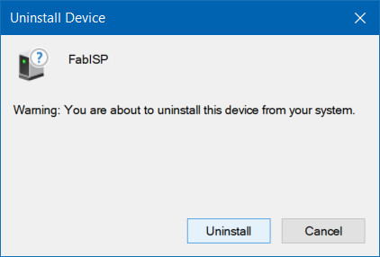
You may see a window pop up similar to the image below. Click on the button labeled Uninstall. In some cases, Windows may provide an option to "Delete the driver software for this device." if the option is provided, simply mark the checkbox before clicking on the button to uninstall.
After uninstalling, power cycle the programmer by unplugging/replugging the Tiny AVR Programmer from the USB port. Head back to the Installing Drivers section and follow the instructions to Automatically Install the Drivers using Zadig.
Error Connecting To AVR Programmer
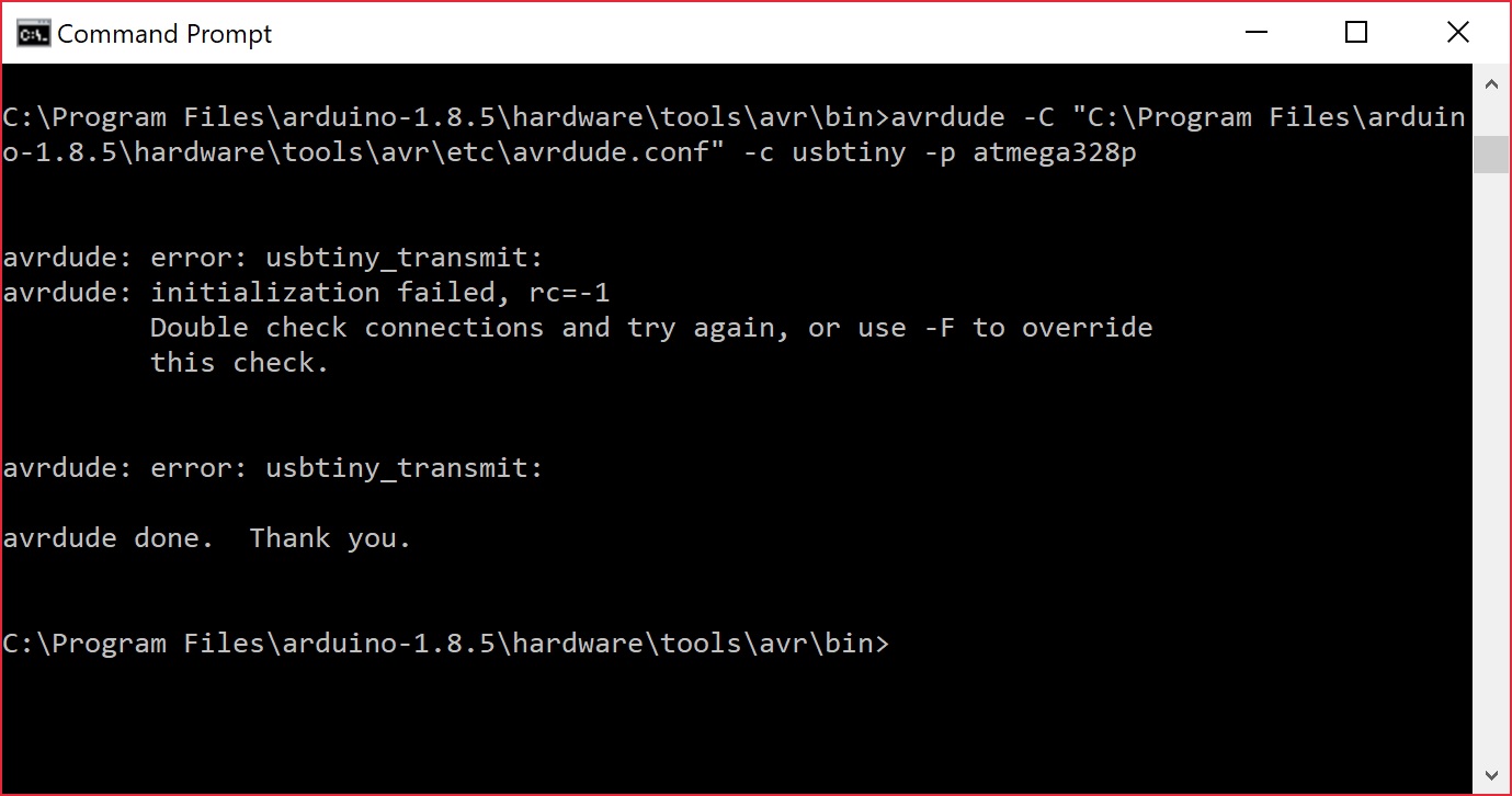
If you receive an error similar to the output below, it is probably due to the connection to the AVR programmer.
language:bash
avrdude: error: usbtiny_transmit:
avrdude: initialization failed, rc=-1
         Double check connections and try again, or use -F to override this check.


avrdude:error: usbtiny_transmit:
One solution is to try to unplug and replug the AVR programmer back to your COM port. You may also want to check the USB cable or ensure that the drivers are installed correctly. The output in the command line may look similar to the screenshot below.
Or do a search online with the error that you are having and check different forums to see if anyone else has run into the same issues as you have.
Resources and Going Further
Now that you've successfully got your Pocket AVR Programmer up and running, it's time to incorporate it into your own project!
Here are some more AVR Pocket Programmer related resources, should you need them:
- Schematic (PDF)
- Eagle Files (ZIP)
- GitHub
- Product Repo -- Here you'll find everything from PCB design files, and firmware to custom enclosure designs.
- Firmware
- Drivers
- Zadig v2.0.1.160 Software and USBtiny (ZIP) -- For automatic installation
- USBTiny libusb-win32 (ZIP) -- For manual installation
- GitHub: Signed USBTiny Drivers -- If the first 3 options fail to install
- AVRDUDE Online Manual
- AVRDUDE Troubleshooting -- Common errors can be found in this troubleshooting section.
We've got plenty more tutorials where that came from. If you're looking for more stuff to learn, or are looking for some project inspiration, check out these tutorials!
- Installing an Arduino Bootloader -- Use your AVR Pocket Programmer to load a bootloader onto an Arduino. This tutorial will teach you what a bootloader is, why you would need to install/reinstall it, and go over the process of doing so.
- Tiny AVR Programmer Hookup Guide -- If you're looking to program ATtiny85's specifically, check out the Tiny AVR Programmer.
- Using the Arduino Pro Mini 3.3V -- If you're already directly programming your Arduino, take it a step further with the Arduino Pro Mini.
- Wireless Arduino Programming with Electric Imp -- If you're feeling constrained by the USB cables, check out this tutorial where we upload code to an Arduino wirelessly!
- Wireless XBee/AVR Bootloading -- Use your AVR Pocket Programmer to upload a custom bootloader, then wirelessly program your Arduino.
Installing an Arduino Bootloader
Using the Arduino Pro Mini 3.3V
Tiny AVR Programmer Hookup Guide
Wireless Arduino Programming with Electric Imp
Are you looking to use a Pi to flash larger file sizes to your AVR microcontrollers? Try checking out the Pi AVR Programmer Hat!