Pocket AVR Programmer Hookup Guide
Board Overview
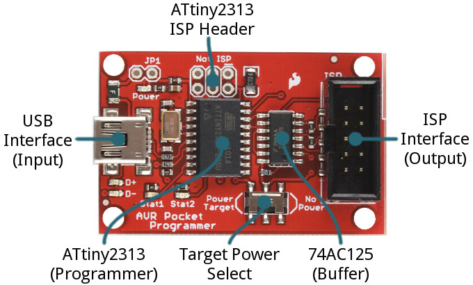
Before we get to using the AVR Pocket Programmer, let's quickly overview what components fill the board out:
- USB Connector -- This is your data and power input to the Programmer. A mini-B USB cable plugs in here and connects your computer to the Programmer.
- 2x5 ISP Header -- This shrouded header mates with the included Programming Cable, and allows you to send the programming signals out to your AVR. It's polarized to make sure you can't plug anything in backwards.
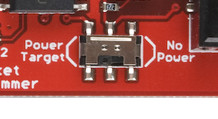
- Power Target Switch -- Unlike a lot of ISP's out there, the AVR Pocket Programmer can deliver power to the AVR-to-be-programmed. Flick this switch to the "Power Target" side, to send 5V to the AVR. More on this below.
- ATtiny2313 -- This is the chip that works the programming magic. It converts between USB and SPI to turn commands from your computer into words and instructions to load into your AVR-to-be-programmed. Unless you want to customize the Tiny ISP firmware, you can leave this chip alone.
- The unpopulated ISP header, above the ATtiny2313, is broken out in case that chip needs to be programmed. It's mostly used in production by those who program the programmers.
- 74AC125 Buffer -- This chip helps to add some protection to the programmer by buffering the data-line outputs. Another IC to mostly ignore.
The board also includes a variety of LEDs to indicate power, status, and data transfers.
AVR ISP Pinouts
AVRs are programmed through an SPI interface. There are six unique signals required for communication between ISP and AVR: VCC, GND, Reset, MOSI, MISO, and SCK.
To route those signals between devices, there are two standardized connectors -- one 10-pin, 2x5 and another 6-pin, 2x3 connector:
The AVR Pocket Programmer includes an on-board 2x5 connector, and the included AVR Programming Cable terminates with both 2x5 and 2x3 connectors.
Power Target Switch
If you're working with an AVR on a breadboard or a prototype, power may be hard to come by. The AVR Pocket Programmer allows you to route 5V out to your AVR. It can deliver upwards of 500mA before tripping the onboard PTC.
If the switch is in the Power Target position, it will route 5V out to your AVR. Otherwise, if the switch is pointing towards No Power, no signal will be connected to the 5V pin on the ISP connector.


