SparkFun Qwiic Micro (SAMD21E) Hookup Guide
 M-Short,
  Elias The Sparkiest,
  bboyho
 Introduction
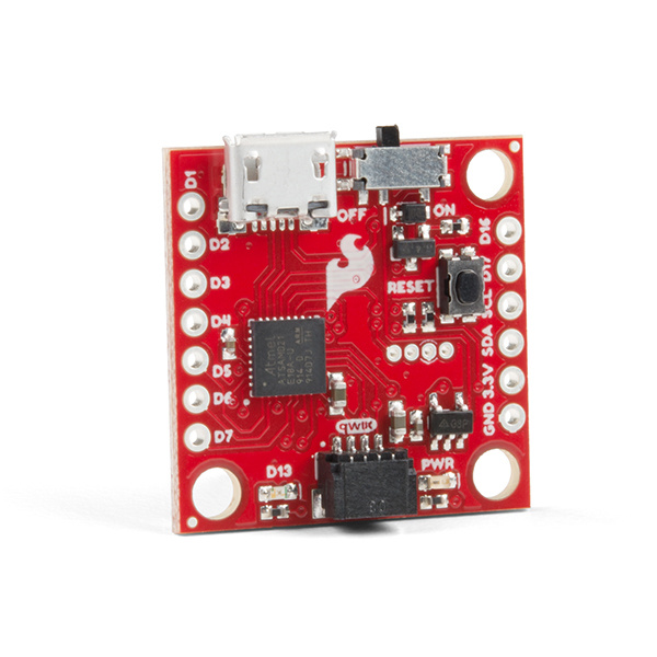
Looking for a one square inch sized microcontroller to use with the Qwiic system? At it's heart is the powerful and versatile ATSAMD21E18, which is an ARM Cortex M0+, 32-bit microcontroller, with 256KB of flash memory that can run at up to 48MHz. We've programmed it with an UF2 Bootloader making the Qwiic Micro easy to program whether you want to use Arduino or CircuitPython. In this hookup guide we'll walk through all of the features available on the SparkFun Qwiic Micro.
Required Materials
In addition to the Qwiic Micro, you'll also need a Micro-B Cable (as if you don't already have dozens in your USB cable drawer!). That's all you'll need to get started. You can also take advantage of its LiPo battery port with a single-cell Lithium Polymer battery. You may not need everything though depending on what you have. Add it to your cart, read through the guide, and adjust the cart as necessary.


Optional Materials
There are a few options to connect and power to the board depending on your project. If you are connecting a Qwiic sensor to the Qwiic connector, you'll need a Qwiic cable. For those that want access to the plated through hole pads on the side, you'll need to solder header pins or wires on the side for a secure connection. For anyone using a LiPo battery with the board, you'll need to solder the JST connector on the back.


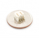
JST Right Angle Connector - White
PRT-08612
Qwiic Cable - 50mm
PRT-14426Tools
Depending on your project, you may need a soldering iron, solder, and general soldering accessories to connect to the plated through hole pads on the side of the board.


Suggested Reading
Before continuing on with this tutorial, you may want to familiarize yourself with some of these topics if they’re unfamiliar to you. If you aren't familiar with the Qwiic system, we recommend reading here for an overview.
| Qwiic Connect System |
Analog to Digital Conversion
What is an Arduino?
Installing Arduino IDE
SAMD21 Mini/Dev Breakout Hookup Guide
Hardware Overview
Before we get into programming the SAMD21, let's first cover some of the features built into the SparkFun Qwiic Micro. The Qwiic Micro is similar to our other SAMD21 boards such as the SAMD21 Dev Breakout, except much much smaller. In this section, we'll cover the hardware on the SparkFun Qwiic Micro, including its I/O pins and the various LEDs. We'll also cover the different options for powering the board.
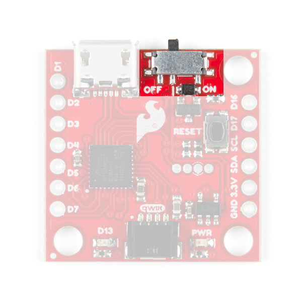
Supplying Power and Power Switch
The SparkFun Qwiic Micro operates at 3.3 volts which makes it ideal for the Qwiic eco-system. Power can be supplied to the SparkFun Qwiic Micro through micro-USB. It is also possible to supply power through the through holes labeled 3V3 and GND located in the lower right hand section of the board.
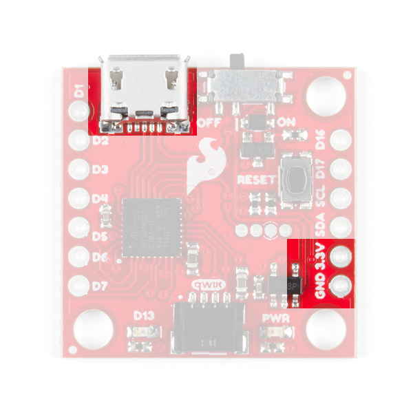
Additionally, we've provided pads for an SMD LiPo battery connector if you have it, see the Optional Circuitry section below. The micro-USB connector should work with one of the many USB phone-charging cables you have lying around, or one of our micro-USB cables. Below is a list of micro-USB options that SparkFun offers.
The power switch on the SparkFun Qwiic Micro controls turns it on and off when put into the on and off position respectively.
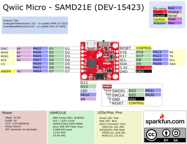
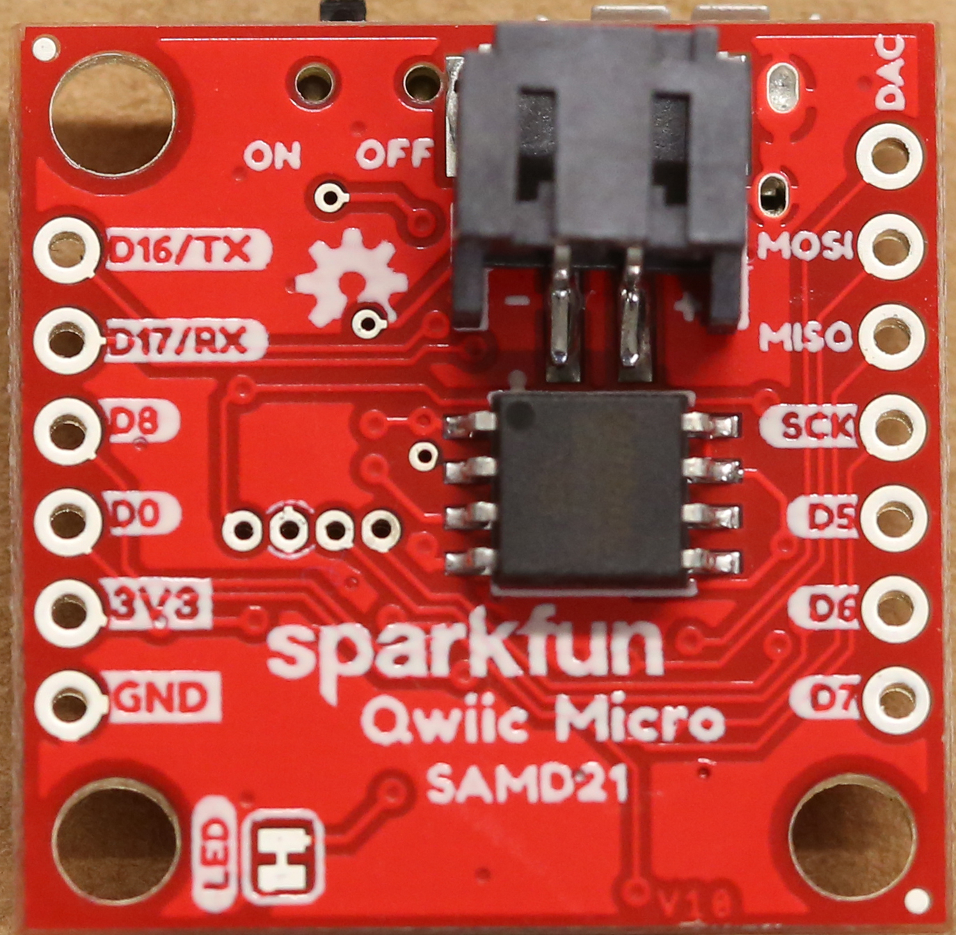
Pin Mapping
⚡ 3.3V Logic Levels! When you start interfacing with the SAMD21's I/O pins using external sensors and other components, keep in mind that each I/O will produce, at most, 3.3V for a high-level output.
When configured as an input, the maximum input voltage for each I/O is 3.6V (VDD+0.3V). If you're interfacing the SAMD21 with 5V devices, you may need some level shifters in between.
The graphical datasheet for the SparkFun Qwiic Micro below, shows the complete functionality of each pin; which pins are analog, digital, where SERCOM ports are located, and which data buses are available. All PWM-capable pins except the DAC are capable of PWM output. The DAC pin provides a true 10-bit analog output. In Example: Analog Input and Output, there are steps on how to take full advantage of this feature.
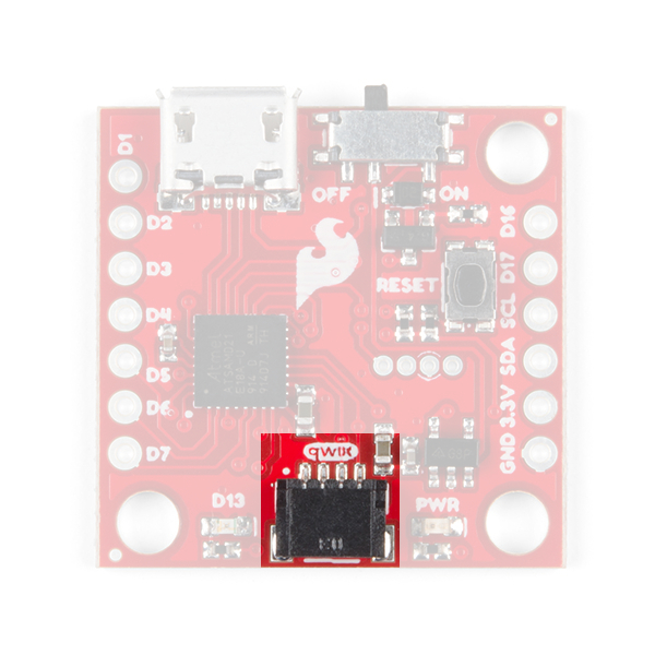
Qwiic Connector
On the opposite edge of the SparkFun Qwiic Micro is a Qwiic connector.
If you're not familar with the Qwiic Ecosystem, the short of it is that we have integrated Qwiic Connectors on many sensors and development boards that allow for quick (get it?) I2C connections through cables rather than soldering. It's an extremely useful tool. Check out the banner below for more information.
LEDs
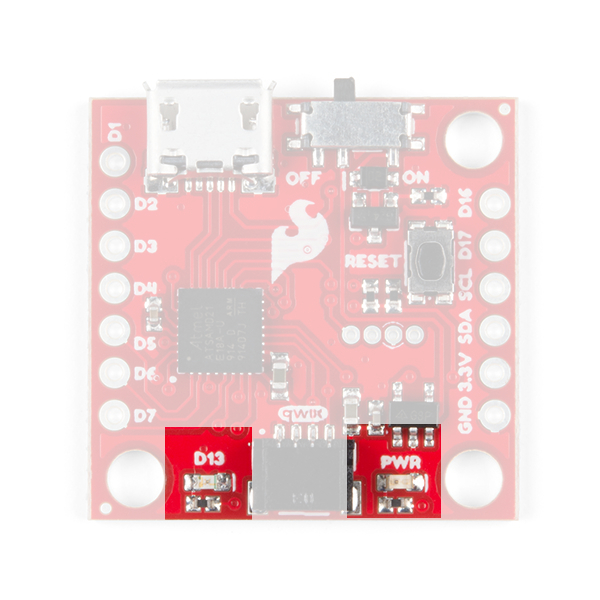
The SparkFun Qwiic Micro has a red power LED that has become emblematic of our Qwiic eco-system and indicates power is being supplied to the board and that the power switch is in the ON position. Additionally, there is a stat LED that is attached to pin D13 and is labeled D13.
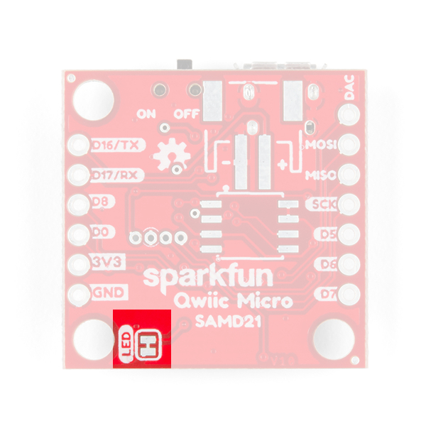
If you want to minimize the current draw of your Qwiic Micro or just don't like the power LED we've provided a jumper on the underside to disconnect it; see Jumper section below.
Jumper
On the underside of the SparkFun Qwiic Micro just below the power LED we've provided a jumper to disconnect the power LED to help keep the current draw of the microcontroller low. Simply take a hobby knife and cut the trace in between the two pads to sever its' connection. Simply re-solder this jumper to reconnect it. If you need some instructions for working with jumper pads then check out our tutorial.
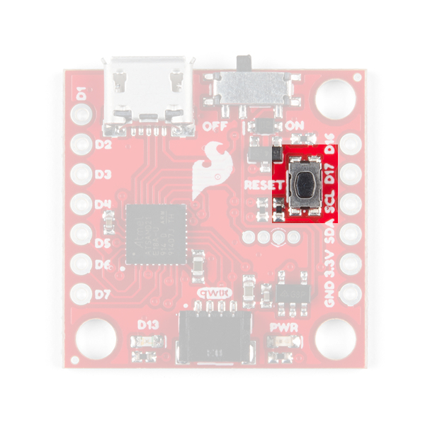
Reset Button
On the topside of the SparkFun Qwiic Micro is a reset button which resets the board when pressed. If you find yourself with a botched Circuit Python installation, or a sketch that has left your board inoperable, then you can tap this button twice to re-enter bootloader mode. You'll know you've done it correctly when the D13 Stat LED is dimming and brightening in a breathing pattern.
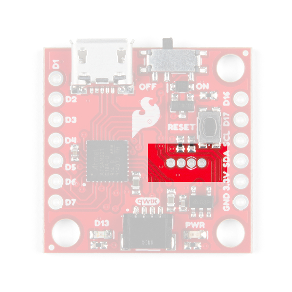
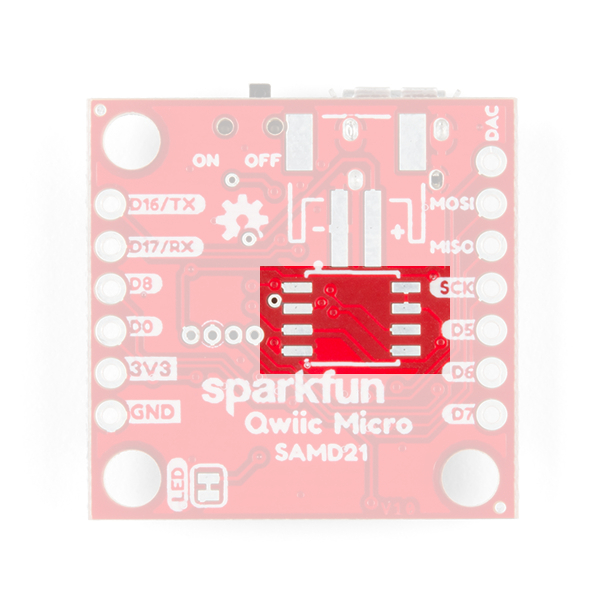
Programming Header
There is a small four pin programming header exposed on both the top and bottom side of the SparkFun Qwiic Micro. This header breaks out the following pins for SWD programming:
 |
 |
| Pins from left to right. | |
|---|---|
| TOP | BOTTOM |
| SWDIO | RESET |
| SWCLK | GND |
| GND | SWCLK |
| RESET | SWDIO |
Programming through this header would allow you to put a different bootloader on the chip, or to configure the SAMD21's flexible SERCOM ports to add another I2C port for example. You can check out this guide to see how this is done.
0Ω Resistor Used to Help Program an AVR Chip via Test Pads
Optional Circuitry
LiPo Battery
On the underside we've included empty pads for a few optional items. First in the upper right is a space for a LiPo Battery Connector. You'll need to solder connector if you decide to power your project though this connector.

We provide a number of LiPo battery options when you're ready to integrate the SparkFun Qwiic Micro into your project.

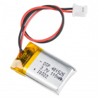


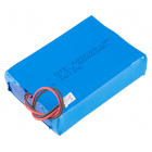

Lithium Ion Battery - 1Ah
PRT-13813Optional Flash Memory Chip
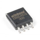
Just below that is a space for a flash memory chip.
If you want to add extra memory to the SparkFun Qwiic Micro than you can solder an 8 pin SOIC to these pads. The 4MB flash chip from Winbond: the W25Q32FV which works with the very useful Arduino Library SPI Memory. Check out Example 4: Flash Memory to see how to use an external flash with the SparkFun Qwiic Micro. In addition we've provided CircuitPython firmware for the SparkFun Qwiic Micro that can use this memory as well.
When everything is soldered onto the bottom, it will look like this:
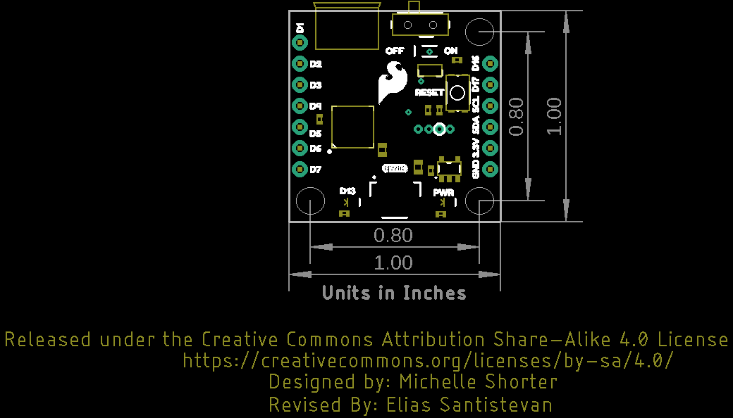
Board Dimensions
The board utilizes the standard 1.0"x1.0" square like a majority of the Qwiic enabled sensors. Due to the size of the board, there are three mounting holes on each corner of the board. Grab some standoffs and screws to make a Qwiic sensing tower of boards!
UF2 Bootloader and Drivers
The SparkFun Qwiic Micro comes with a UF2 bootloader which has the unique benefit of sidestepping driver installation on modern operating systems like Windows 10, Mac, and Linux! The UF2 bootloader turns the SparkFun Qwiic Micro into a USB mass storage device and so behaves like a flash drive when you plug it into your computer. However in the Arduino IDE, nothing will change: you'll still select its COM Port when uploading your code.
....yes but what is UF2?
UF2 stands for USB Flashing Format, which was developed by Microsoft for PXT (now known as MakeCode) for flashing microcontrollers over the Mass Storage Class (MSC), just like a removable flash drive. The file format is unique, so unfortunately, you cannot simply drag and drop a compiled binary or hex file onto the Qwiic Micro. Instead, the format of the file has extra information to tell the processor where the data goes, in addition to the data itself.
For Arduino users, the UF2 bootloader is BOSSA compatible, which the Arduino IDE expects on ATSAMD boards. For more information about UF2, you can read more from the MakeCode blog, as well as the UF2 file format specifiation.
Windows 7
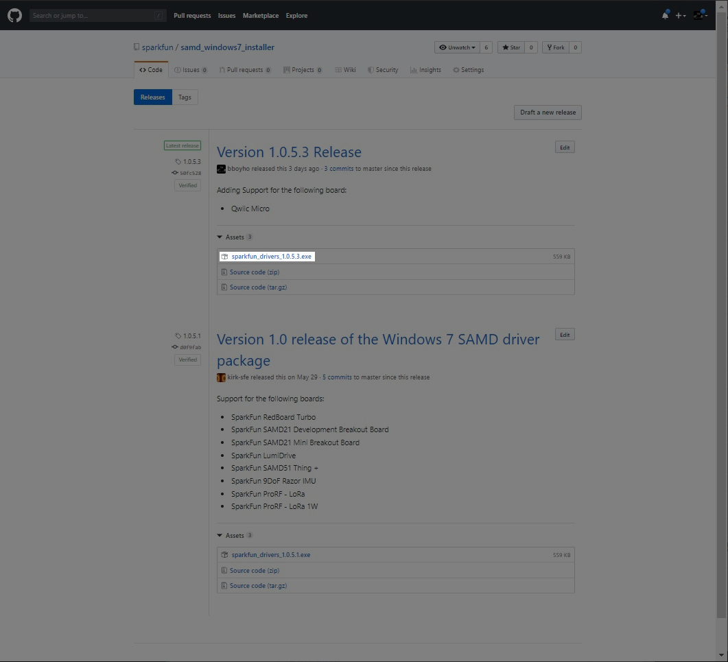
Unfortunately if you are using a Windows 7 OS, you will still need to install the SAMD drivers using the SAMD Windows 7 Installer. Head over to the GitHub repo to install the executable. Otherwise skip ahead to Setting Up Arduino.
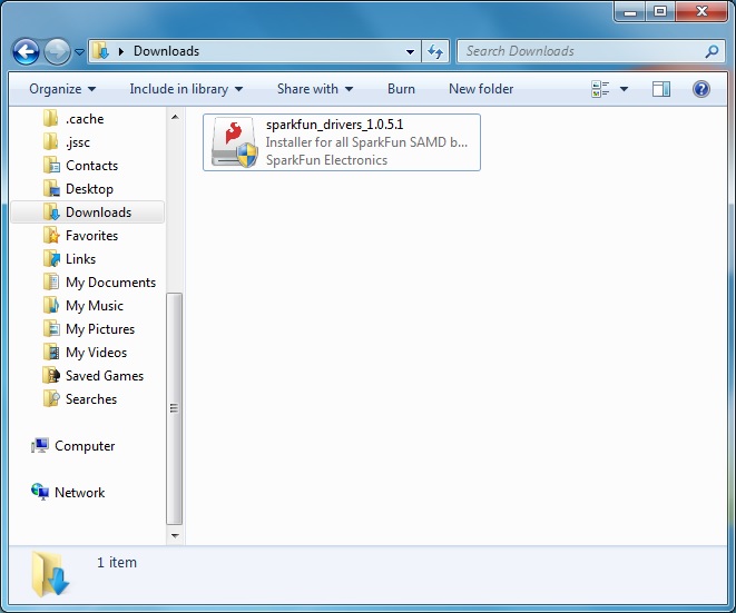
Scroll down the page to the assets in the Latest release and click on the '.exe to download. The version number may be different depending on the release. The image below shows sparkfun_drivers_1.0.5.3.exe .
After downloading, click on the executable and follow the prompts to install. The steps to install are the same even though the following images show drivers for v1.0.5.1.
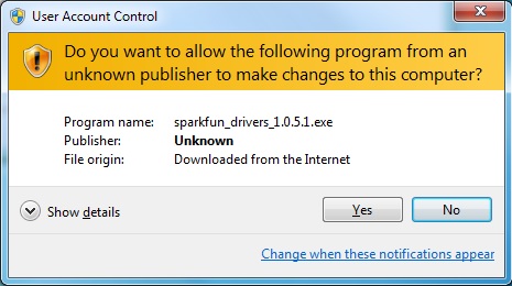
You will receive a warning from Windows. Click yes to continue.
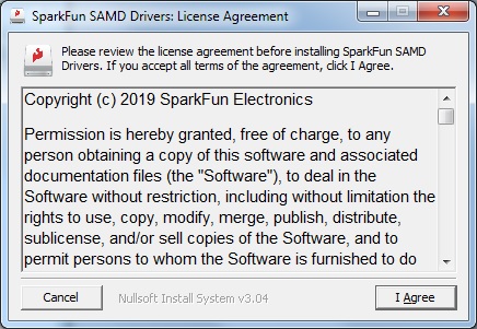
Another window will pop up. Read through the license and click "I Agree".
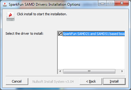
When ready, hit the Install button.
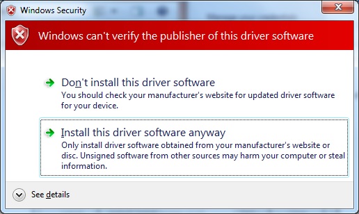
Another window will pop up. Click on "Install this driver software anyway" to continue.
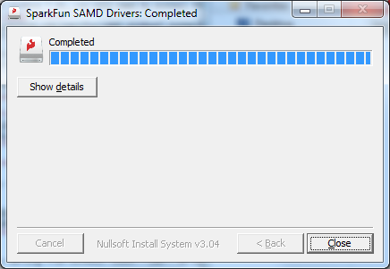
Your Windows 7 will begin installing the driver. This should take a few seconds. When the drivers have installed, hit the "Close" button to exit out of the installer.
Setting Up Arduino
While the SAMD21 alone is powerful enough, what truly makes it special is its growing support in the Arduino IDE. With just a couple click's, copies, and pastes, you can add ARM Cortex-M0+-support to your Arduino IDE. This page will list every step required for getting SparkFun Qwiic Micro installed into the Arduino IDE.
Update Arduino! This setup requires at least Arduino version 1.6.4 or later. We've tested it on 1.6.5 and the latest version – 1.8.8. If you're running an older version of Arduino, consider visiting arduino.cc to get the latest, greatest release.
Install Arduino SAMD Board Add-Ons
First, you'll need to install a variety of tools, including low-level ARM Cortex libraries full of generic code, arm-gcc to compile your code, and bossa to upload over the bootloader. These tools come packaged along with Arduino's SAMD board definitions for the Arduino Zero.
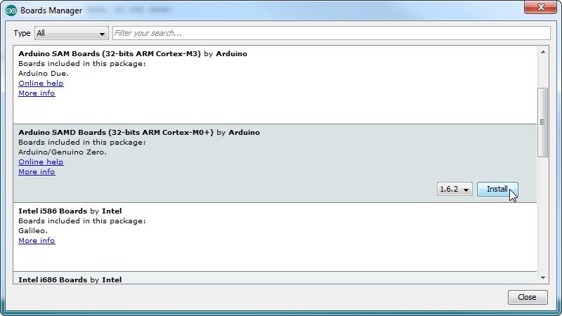
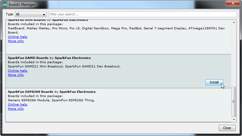
To install the Arduino SAMD board definitions, navigate to your board manager (Tools > Board > Boards Manager...), then find an entry for Arduino SAMD Boards (32-bits ARM Cortex-M0+). Select it, and install the latest version (recently updated to v1.8.4).
Downloading and installing the tools may take a couple minutes -- arm-gcc in particular will take the longest, it's about 250MB unpacked.
Once installed, Arduino-blue "Installed" text should appear next to the SAMD boards list entry.
Install SparkFun Board Add-On
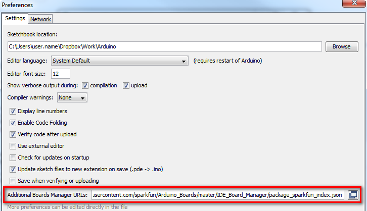
Now that your ARM tools are installed, one last bit of setup is required to add support for the SparkFun SAMD boards. First, open your Arduino preferences (File > Preferences). Then find the Additional Board Manager URLs text box, and paste the below link in:
https://raw.githubusercontent.com/sparkfun/Arduino_Boards/main/IDE_Board_Manager/package_sparkfun_index.json
Then hit "OK", and travel back to the Board Manager menu. You should (but probably won't) be able to find a new entry for SparkFun SAMD Boards. If you don't see it, close the board manager and open it again. ¯\_(ツ)_/¯.
This installation should be much faster; you've already done the heavy lifting in the previous section. When writing this tutorial, the board version used in this tutorial should be v1.7.0. You may have a higher version as the board if there are any updates.
Select the Board and Serial Port
Once the board is installed, you should see a new entry in your Tools > Board list. Select your SparkFun Qwiic Micro.
Finally, select the SparkFun Qwiic Micro's port when the board is connected to your computer with the power switch in the ON position. Navigate back up to the Tool > Port menu. The port menu will have the SparkFun Qwiic Micro's port, labeled as such here. On a Windows machine, the serial port should come in the form of "COM#". On a Mac or Linux machine, the port will look like "/dev/cu.usbmodem####".
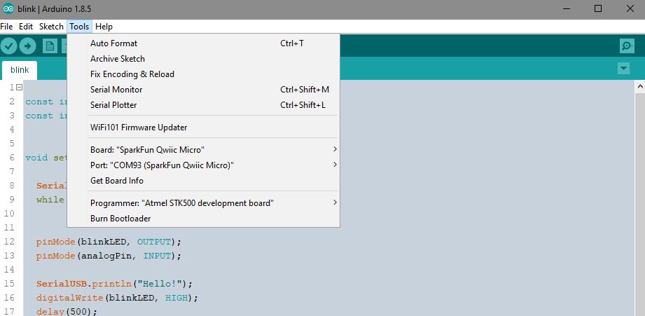
In the picture above my Qwiic Micro is listed under COM93; this is because I've plugged in about as many microcontrollers into my computer, but the one in your port menu should be a lot smaller.
Example 1: Blink
Here's a quick example sketch to get the iconic blinking blue stat LED for Arduino blinking on the SparkFun Qwiic Micro; simply copy and paste from below, then click upload!
language:c
const int LED = 13; // Blue "stat" LED on pin 13

void setup()
{
  pinMode(LED, OUTPUT); //set pin as output
  digitalWrite(LED, LOW); //turn LED off
}

void loop()
{

  digitalWrite(LED, HIGH); // Blue LED on
  delay(250);
  digitalWrite(LED, LOW); // Blue LED off
  delay(250);
}
Now that you've passed the Arduino litmus test, you're all set up to start building your first project. If you haven't already, go check out our Qwiic eco-system which allows you to easily connect with sensors and other devices without the need for soldering.
In addition each add-on board within this eco-system has a library to get you started right away. For example, do you want to turn on a lamp with your SparkFun Qwiic Micro, better yet four lamps, or perhaps you'd like to see how much light your plants are getting? Check out any tutorial tagged with Arduino, sensor, and Qwiic for more ideas!
Spectral Triad (AS7265x) Hookup Guide
Real Time Clock Module - RV-8803 (Qwiic) Hookup Guide
SparkFun Qwiic GPIO Hookup Guide
Qwiic Haptic Driver DA7280 Hookup Guide
Example 2: Serial Ports
One of the SAMD21's most exciting features is SERCOM -- its multiple, configurable serial ports. The Arduino IDE equips the SAMD21 with a hardware serial port, by default, plus a "USB serial port" for communicating between the serial monitor.
Each of these serial ports has a unique Serial object which you'll refer to in code:
| Serial Object | Serial Port | RX Pin | TX Pin |
|---|---|---|---|
SerialUSB | USB Serial (Serial Monitor) | ||
Serial | Hardware Serial Port | D16 | D17 |
There are a couple critical things to notice here. First of all, if you're trying to use the Serial Monitor to debug, you'll need to use SerialUSB.begin(<baud>) and SerialUSB.print(). (Thankfully find/replace exists for adjusting example code.) You can also add #define Serial SerialUSB to the beginning of a sketch. This will tell the IDE to replace "Serial" with "SerialUSB" everywhere it sees it before it compiles.
Here's a quick example demonstrating the differences between Serial Monitor and Serial. It is designed to route data from Serial to the Serial Monitor, and vice-versa.
language:c
void setup()
{
  SerialUSB.begin(9600); // Initialize Serial Monitor USB
  Serial.begin(9600); // Initialize hardware serial port, pins 17/16

  while (!SerialUSB) ; // Wait for Serial monitor to open

  // Send a welcome message to the serial monitor:
  SerialUSB.println("Send character(s) to relay it over Serial");
}

void loop()
{
  if (SerialUSB.available()) // If data is sent to the monitor
  {
    String toSend = ""; // Create a new string
    while (SerialUSB.available()) // While data is available
    {
      // Read from SerialUSB and add to the string:
      toSend += (char)SerialUSB.read();
    }
    // Print a message stating what we're sending:
    SerialUSB.println("Sending " + toSend + " to Serial");

    // Send the assembled string out over the hardware
    // Serial port (TX pin 1).
    Serial.print(toSend);
  }

  if (Serial.available()) // If data is sent from device
  {
    String toSend = ""; // Create a new string
    while (Serial.available()) // While data is available
    {
      // Read from hardware port and add to the string:
      toSend += (char)Serial.read();
    }
    // Print a message stating what we've received:
    SerialUSB.println("Received " + toSend + " from Serial");
  }
}
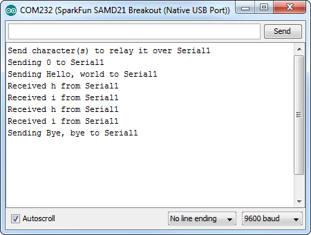
Then try typing something into the serial monitor. Even with nothing connected to the hardware serial port, you should see what you typed echoed back at you. It should look similar to the image below similar to the SAMD21 breakout.
You can further test this sketch out by connecting an 3.3V FTDI Basic or any other serial device to the SAMD21's pins 17 (RX) and 16 (TX). You'll need IC hooks for a quick temporary connection. Otherwise, you'll need to solder pins or wires to the board. By opening up a serial terminal, any data sent from the FTDI should end up in your Arduino Serial Monitor, and data sent to your Arduino Serial Monitor will route over to the FTDI. Here's a table that shows what pins to connect together.
| Qwiic Micro Pins | 3.3V FTDI (or any USB-to-Serial Converter) Pins |
|---|---|
| D16/TX | TXO |
| D17/RX | RXI |
| GND | GND |
Example 3: Analog Input and Output
While it still has PWM-based "analog outputs", the SAMD21 also features true analog output in the form of a digital-to-analog converter (DAC). This module can produce an analog voltage between 0 and 3.3V. It can be used to produce audio with more natural sound, or as a kind of "digital potentiometer" to control analog devices.
The DAC is only available on the Arduino pin A0, and is controlled using analogWrite(A0, <value>). The DAC can be set up to 10-bit resolution (make sure to call analogWriteResolution(10) in your setup), which means values between 0 and 1023 will set the voltage to somewhere between 0 and 3.3V.
In addition to the DAC, the SAMD21's ADC channels also stand apart from the ATmega328: they're equipped with up to 12-bit resolution. That means the analog input values can range from 0-4095, representing a voltage between 0 and 3.3V. To use the ADC's in 12-bit mode, make sure you call analogReadResolution(12) in your setup.
Serial Plotting the DAC
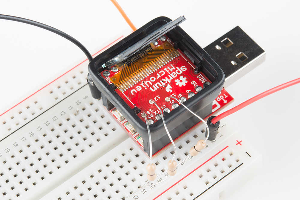
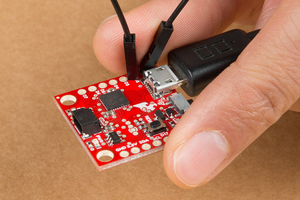
Here's an example that demonstrates both the 10-bit DAC and the 12-bit ADC. To set the experiment up, connect A0 to A1 with a jumper -- we'll drive A0 with an analog voltage, then read it with A1. To keep the board size to a minimum, we were not able to include additional labels for each pin's functions. Therefore, A0 is labeled as D1/DAC and A1 is labeled as D2. Since there are no headers soldered, you will need to hold the jumper wire in place to with your thumb and index finger for a temporary connection. It's the simplest circuit we've ever put in a tutorial:
Then copy and paste the code below into your Arduino IDE, and upload!
language:c
// Connect A0 to A1, then open the Serial Plotter.

#define DAC_PIN A0 // Make code a bit more legible

float x = 0; // Value to take the sin of
float increment = 0.02;  // Value to increment x by each time
int frequency = 440; // Frequency of sine wave

void setup()
{
  analogWriteResolution(10); // Set analog out resolution to max, 10-bits
  analogReadResolution(12); // Set analog input resolution to max, 12-bits

  SerialUSB.begin(9600);
}

void loop()
{
  // Generate a voltage value between 0 and 1023.
  // Let's scale a sin wave between those values:
  // Offset by 511.5, then multiply sin by 511.5.
  int dacVoltage = (int)(511.5 + 511.5 * sin(x));
  x += increment; // Increase value of x

  // Generate a voltage between 0 and 3.3V.
  // 0= 0V, 1023=3.3V, 512=1.65V, etc.
  analogWrite(DAC_PIN, dacVoltage);

  // Now read A1 (connected to A0), and convert that
  // 12-bit ADC value to a voltage between 0 and 3.3.
  float voltage = analogRead(A1) * 3.3 / 4096.0;
  SerialUSB.println(voltage); // Print the voltage.
  delay(1); // Delay 1ms
}
This sketch produces a sine wave output on A0, with values ranging from 0 to 3.3V. Then it uses A1 to read that output into its 12-bit ADC, and convert it into a voltage between 0 and 3.3V.
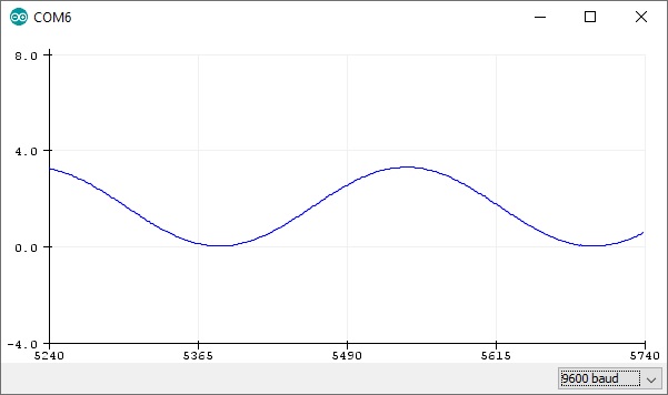
You can, of course, open the serial monitor to view the voltage values stream by. But if the sine wave is hard to visualize through text, check out Arduino's new Serial Plotter, by going to Tools > Serial Plotter.
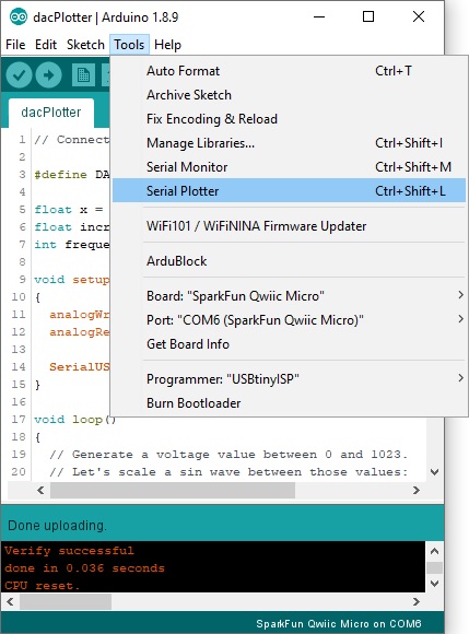
And take in the majesty of that sine wave. Since we are temporarily holding the jumper wire in place with our fingers, the sine wave may not be perfect whenever you release pressure on the jumper wire.
Example 4: Flash Memory with SPIMemory
Installing the SPI Memory Arduino Library
The following example shows you the basic way to start writing information to the optional flash memory that can be soldered to the underside of the SparkFun Qwiic Micro. The example simply shows you how to set up the code to interact with the flash chip and demonstrates this by writing a single number to an address space on it.
To begin you'll first need to download and install the SPIMemory Arduino Library. You can download it directly from the GitHub Repo or download a zip from the button below. If you've never installed a library before then follow our helpful tutorial here for directions on how to do it.
Example Code
The setup is a bit different than the example code supplied by the library because the flash is connected to a seperate SPI bus that is different then the default one broken out to the SparkFun Qwiic Micro's headers. At the top we use the library by calling SPIFlash and creating an instance of the library, calling it flash. Flash takes two arguments: the flash chip's chip select pin, and secondly the alternate SPI port to be used. Since the memory chip is on SPI1, we'll give it that but precede it with an ampersand as demonstrated: &SPI1.
language:c
#include "SPIMemory.h"

const int blinkLED = 13;
const int flashCS = 21; // Chip select for Flash

SPIFlash flash(flashCS, &SPI1); // Our Flash is on a different SPI bus

unsigned long addr = 0x01; // Random selection
byte data = 0x03; // Random data
In the setup, confirm we enable SPI1 bus with SPI1.begin() and that's all you need! Further into the setup, we erase the address that's going to be written to, and then write to it. We double check this was done correctly by reading that address to the serial monitor. Just make sure to set the baud rate at 115200 to view the output.
language:c
void setup(){

    SPI1.begin(); // Don't forget to begin SPI!
    flash.begin();
    SerialUSB.begin(115200);
    while(!SerialUSB) {} // Wait until the Serial Port is opened.
    SerialUSB.println("Hello!");

    if(flash.eraseBlock32K(addr)){ // Erase the blacok
        SerialUSB.println("Block erased.");
    }
    else
        SerialUSB.println("Error.");

    if(flash.writeByte(addr, data, true)){
        SerialUSB.println("Written: ");
        SerialUSB.println(flash.readByte(addr));
    }
    else
        SerialUSB.println("Nothing written");

    }

void loop(){

    digitalWrite(blinkLED, HIGH);
    delay(500);
    digitalWrite(blinkLED, LOW);
    delay(500);

}
CircuitPython
CircuitPython is Adafruit's version of MicroPython. We like it here at SparkFun because of it's support for the SAMD based microcontrollers. If you're not familiar with CircuitPython, then I encourage you to check Adafruit's website for more information.
We've provided two different CircuitPython builds for the Qwiic Micro in the Qwiic Micro's hardware repo, one for those of you have soldered the flash chip sold on SparkFun and one for those without flash chip. You can also get both firmware zip files by clicking the respective buttons below. If you're not familiar with the optional flash chip you can add to the SparkFun Qwiic Micro, head back to the Hardware Overview and take a look.
Inside the zipped file are three different files which all do the same things. One of the files has a .uf2 file extension which is designed to work with UF2 bootloaders. In the next section, we'll focus on installing CircuitPython using this method.
Installing CircuitPython
When you plug the SparkFun Qwiic Micro into your computer, it should pop up in a window titled Qwiic Micro like the one below. If not, press the reset button twice.
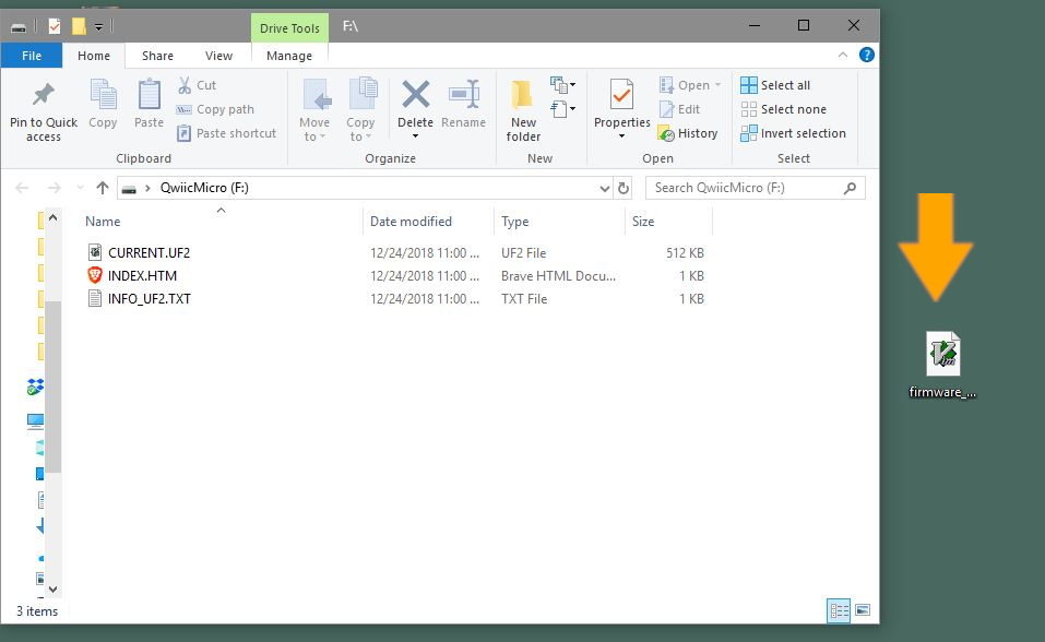
To the right of the SparkFun Qwiic Micro pop up window is the firmware_no_flash.uf2 file from the zipped file's firmware folder that will install CircuitPython. Again, if you've soldered the flash chip, then you'll choose the firmware_with_flash.uf2 file instead. To install the file, simply drag the .uf2 from the desktop into the SparkFun Qwiic Micro window. The window should close and the re-open but this time it will be titled CIRCUITPY.
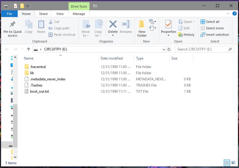
That's it!
Reinstalling CircuitPython
If you've installed CircuitPython but have decided to use Arduino instead, but then decided to use CircuitPython again (make up your mind), then use the following instructions to reinstall CircuitPython onto the SparkFun Qwiic Micro. I'll assume you know where to get the CircuitPython firmware files since you had to follow the instructions to install CircuitPython to get to this point. Hint: there in the Installing CircuitPython section above.
Reset Board to Bootloader
We want the board to reset to the UF2 bootloader (which as mentioned above) enables the board to act like a flash drive. After plugging the SparkFun Qwiic Micro into your computer, double tap the reset button. If done correctly, the board will pop up as a removable drive titled Qwiic Micro and the D13 LED will have a slow breathing pattern. Now it's just a matter of dragging the .uf2 Circuit Python file into the Qwiic Micro window. It will close and re-open in a window now titled CIRCUITPY.
Using CircuitPython
If this is your first foray into CircuitPython, then I urge you to visit Adafruit's website to learn about everything CircuitPython.
Troubleshooting
For troubleshooting tips, checkout the SAMD21 Troubleshooting guide here for common issues that you might run into when using the SAMD21 with Arduino. The only exception is that the Qwiic Micro does not require drivers so tips for re-installing drivers will not apply.
Resources and Going Further
There is a wealth of information out there, whether you're looking for datasheets, schematics, or design files. Additional resources, here are a few links you might find handy:
SparkFun Qwiic Micro Design Resources
- CircuitPython
- What is CircuitPython?
- CircuitPython API Reference -- Exhaustive documentation hub for all CircuitPython API.
- CircuitPython GitHub Repository -- Home base for all CircuitPython-related source and tools.
- Building CircuitPython Tutorial -- If you want to build a CircuitPython variant of your own, give this a read.
- ATmel ATSAMD21 Resources
- Arduino ATSAMD21 Resources
- SFE Product Showcase
For more information about adding more SERCOM ports for your SAMD-based board, check out the tutorial below.
Adding More SERCOM Ports for SAMD Boards
It's a brave new world out there -- Arduinos and ARMs working together! What are you going to create with your powerful, Qwiic Micro? Looking for some inspiration, check out these tutorials!
ARM Programming
Qwiic Digital Indoor Thermometer
Qwiic GPS Clock
Or check out this demo (2:00 minutes into the video) to make a smart watch with an Qwiic RTC and Qwiic accelerometer too keep track of time or the amount of steps that you have taken !