SparkFun Qwiic Micro (SAMD21E) Hookup Guide
 M-Short,
  Elias The Sparkiest,
  bboyho
Example 3: Analog Input and Output
While it still has PWM-based "analog outputs", the SAMD21 also features true analog output in the form of a digital-to-analog converter (DAC). This module can produce an analog voltage between 0 and 3.3V. It can be used to produce audio with more natural sound, or as a kind of "digital potentiometer" to control analog devices.
The DAC is only available on the Arduino pin A0, and is controlled using analogWrite(A0, <value>). The DAC can be set up to 10-bit resolution (make sure to call analogWriteResolution(10) in your setup), which means values between 0 and 1023 will set the voltage to somewhere between 0 and 3.3V.
In addition to the DAC, the SAMD21's ADC channels also stand apart from the ATmega328: they're equipped with up to 12-bit resolution. That means the analog input values can range from 0-4095, representing a voltage between 0 and 3.3V. To use the ADC's in 12-bit mode, make sure you call analogReadResolution(12) in your setup.
Serial Plotting the DAC
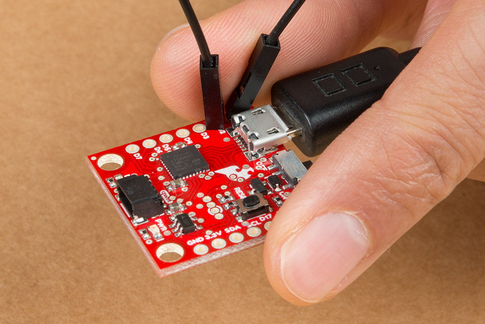
Here's an example that demonstrates both the 10-bit DAC and the 12-bit ADC. To set the experiment up, connect A0 to A1 with a jumper -- we'll drive A0 with an analog voltage, then read it with A1. To keep the board size to a minimum, we were not able to include additional labels for each pin's functions. Therefore, A0 is labeled as D1/DAC and A1 is labeled as D2. Since there are no headers soldered, you will need to hold the jumper wire in place to with your thumb and index finger for a temporary connection. It's the simplest circuit we've ever put in a tutorial:
Then copy and paste the code below into your Arduino IDE, and upload!
language:c
// Connect A0 to A1, then open the Serial Plotter.

#define DAC_PIN A0 // Make code a bit more legible

float x = 0; // Value to take the sin of
float increment = 0.02;  // Value to increment x by each time
int frequency = 440; // Frequency of sine wave

void setup()
{
  analogWriteResolution(10); // Set analog out resolution to max, 10-bits
  analogReadResolution(12); // Set analog input resolution to max, 12-bits

  SerialUSB.begin(9600);
}

void loop()
{
  // Generate a voltage value between 0 and 1023.
  // Let's scale a sin wave between those values:
  // Offset by 511.5, then multiply sin by 511.5.
  int dacVoltage = (int)(511.5 + 511.5 * sin(x));
  x += increment; // Increase value of x

  // Generate a voltage between 0 and 3.3V.
  // 0= 0V, 1023=3.3V, 512=1.65V, etc.
  analogWrite(DAC_PIN, dacVoltage);

  // Now read A1 (connected to A0), and convert that
  // 12-bit ADC value to a voltage between 0 and 3.3.
  float voltage = analogRead(A1) * 3.3 / 4096.0;
  SerialUSB.println(voltage); // Print the voltage.
  delay(1); // Delay 1ms
}
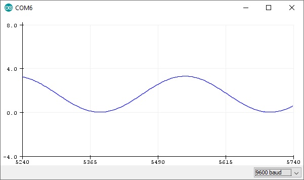
This sketch produces a sine wave output on A0, with values ranging from 0 to 3.3V. Then it uses A1 to read that output into its 12-bit ADC, and convert it into a voltage between 0 and 3.3V.
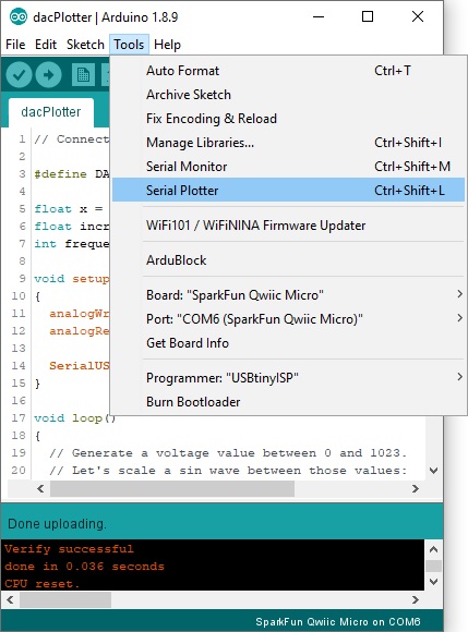
You can, of course, open the serial monitor to view the voltage values stream by. But if the sine wave is hard to visualize through text, check out Arduino's new Serial Plotter, by going to Tools > Serial Plotter.
And take in the majesty of that sine wave. Since we are temporarily holding the jumper wire in place with our fingers, the sine wave may not be perfect whenever you release pressure on the jumper wire.