MicroMod GNSS Function Board - NEO-M9N Hookup Guide
 bboyho,
  Elias The Sparkiest
 Introduction
The u-blox NEO-M9N is a powerful GPS unit that now comes populated on a MicroMod Function Board! In this tutorial, we will quickly get you set up using it with the MicroMod ecosystem and Arduino so that you can start reading the output.

Required Materials
To follow along with this tutorial, you will need the following materials. You may not need everything though depending on what you have. Add it to your cart, read through the guide, and adjust the cart as necessary.

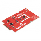
SparkFun MicroMod Main Board - Single
DEV-18575MicroMod Main Board
To hold the processor board and function board, you will need one Main Board. Depending on your application, you may choose to have one or two additional function boards.
SparkFun MicroMod Main Board - Single
DEV-18575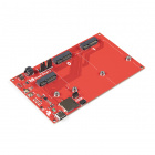
SparkFun MicroMod Main Board - Double
DEV-18576MicroMod Processor Board
There are a variety of MicroMod Processor Boards available to choose from. We recommend getting the ones that are Arduino compatible.
MicroMod Function Board
To add additional functionality to your Processor Board, you'll want to include one or two function boards when connecting them to the Main Board. Besides the NEO-M9N, you could add an additional function board for your project if you have the Main Board - Double.
SparkFun MicroMod LoRa Function Board
WRL-18573Tools
You will need a screw driver to secure the Processor and Function boards.

Suggested Reading
If you aren't familiar with the MicroMod ecosystem, we recommend reading here for an overview.
| MicroMod Ecosystem |
If you aren’t familiar with the following concepts, we also recommend checking out a few of these tutorials before continuing. Make sure to check the respective hookup guides for your processor board and function board to ensure that you are installing the correct USB-to-serial converter. You may also need to follow additional instructions that are not outlined in this tutorial to install the appropriate software.
GPS Basics
Serial Peripheral Interface (SPI)
I2C
How to Work with Jumper Pads and PCB Traces
Getting Started with U-Center for u-blox
Three Quick Tips About Using U.FL
Getting Started with MicroMod
MicroMod Main Board Hookup Guide
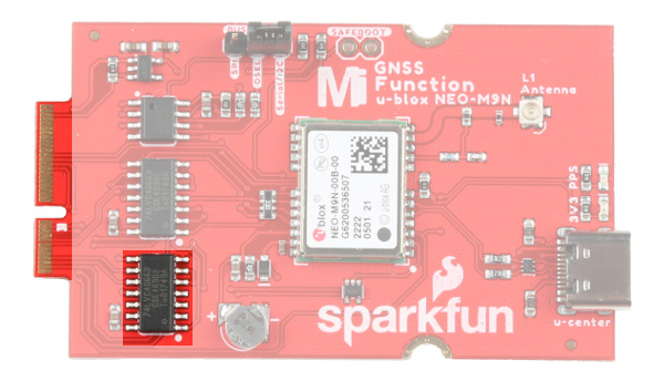
Hardware Overview
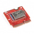
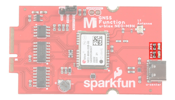
We've taken the u-blox NEO-M9N and broken the board out to a MicroMod Function Board! In this section, we will go over the main features of the Function Board.
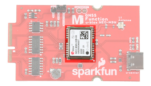
For a detailed overview of the module, these integrated systems and how to use them, refer to the datasheet and integration manual linked in the Resources and Going Further.
Power
To power the board, you will need to apply power to a SparkFun Main Board. Power applied from the M.2 connector VCC line will be regulated down with the 3.3V/600mA AP2112K voltage regulator.

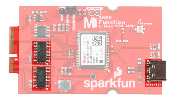
Communication Ports
The NEO-M9N has four communication ports. You can read NMEA data over I2C while you send configuration commands over the UART and vice/versa. The only limit is that the SPI pins are mapped onto the I2C and UART pins so it’s either SPI or I2C+UART. You will need select the port with the BUS SELECT jumper. The USB port is available at all times. There is a bilateral switch between the M.2 connector and the NEO-M9N's Serial, SPI, and I2C ports. The switch connects the appropriate port depending on the on the jumper position.
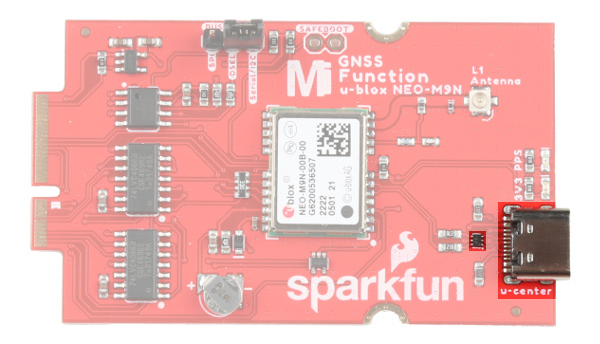
USB
The USB C connector is available for those that are interested in using the u-center software on a computer. There is a TVS diode between the USB port and NEO-M9N's USB data pins for protection.
I2C (a.k.a DDC)
The u-blox NEO-M9N has a “DDC” port which is really just an I2C port (without all the fuss of trademark issues). These pins are shared with the SPI pins. Connecting the DSEL pin to the Serial/I2C with the 2-pin jumper disables the SPI data bus while keeping the UART and I2C interface available.
UART/Serial
The classic serial pins are available on the NEO-M9N but are shared with the SPI pins. Connecting the DSEL pin to the Serial/I2C with the 2-pin jumper disables the SPI data bus while keeping the UART and I2C interface available.
- TXO/SDO = TX out from NEO-M9N
- RXI/SDI = RX into NEO-M9N
SPI
The NEO-M9N can also be configured for SPI communication. Connecting the DSEL pin to the SPI with the 2-pin jumper enables the SPI data bus thus disabling the UART functions on those lines. This also disables I2C interface.
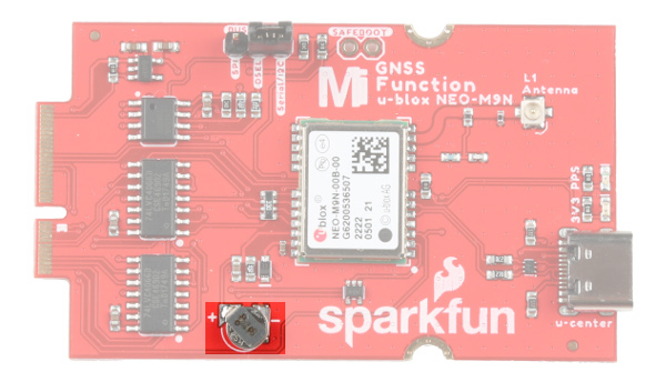
Backup Battery
The small metal disk is a small lithium battery. This battery does not provide power to the IC like the 3.3V system does, but to relevant systems inside the IC that allow for a quick reconnection to satellites. The time to first fix will about ~29 seconds, but after it has a lock, that battery will allow for a two second time to first fix. This is known as a hot start and lasts for four hours after the board is powered down. The battery provides over a years worth of power to the backup system and charges slowly when the board is powered. To charge it to full, leave your module plugged in for 48 hours.
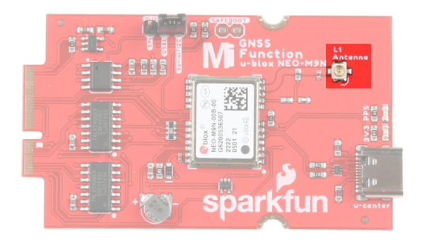
u.FL Connector
The MicroMod GNSS Function Board includes a u.FL connector for a secure connection with a patch antenna. Depending on the antenna, you may need a u.FL adapter to connect. The u.FL connector was added as a design choice for users that decide to place the MicroMod Main Board with the GNSS Function Board in an enclosure. With the u.FL adapter, the SMA connector can be mounted to the enclosure. For more information on working with u.FL connectors, we recommend checking out our tutorial about using u.FL connectors.
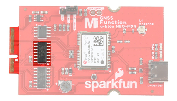
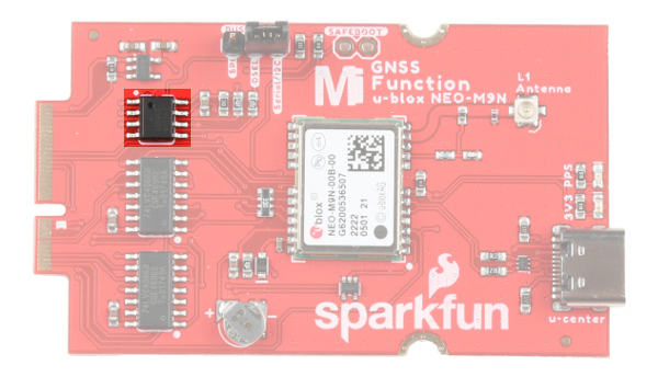
EEPROM
The board includes an I2C EEPROM. Unfortunately, this is not available for the user and was meant to hold board specific information.
LEDs
The board includes two status LEDs.
- 3V3: The
3V3LED indicates when the board is powered. This LED is connected to the 3.3V line. - PPS: The
PPSLED is connected to the Pulse Per Second line. When connected to a satellite, this line generates a pulse that is synchronized with a GPS or UTC time grid. By default, you'll see one pulse a second.
Jumpers
The board includes a few jumpers to configure the NEO-M9N module. For more information, check out our tutorial on working with jumper pads and PCB traces.
- I2C Pull-up Resistors - This three way jumper labeled
I2Cconnects two pull-up resistors to the I2C data lines. If you have many devices on your I2C data lines, then you may consider cutting these. - WP - Adding solder to the jumper pad will disable write protect for the EEPROM.
- 3V3 - The jumper on the opposite side of the board with the label
3V3is connected to the 3V3 LED. Cutting this jumper will disable the LED. - PPS - The jumper on the opposite side of the board with the label
PPSis connected to the PPS LED. Cutting this jumper will disable the LED. - Bus Select
- SPI - Connecting the
DSELpin to theSPIwith the 2-pin jumper enables the SPI data bus thus disabling the UART functions on those lines. This also disables I2C interface. - DSEL - This pin is connected to the NEO-M9N's D_SEL pin to select the interface. Connecting this pin to either side will select the communication protocol.
- Serial/I2C - Connecting the
DSELpin to theSerial/I2Cwith the 2-pin jumper disables the SPI data bus while keeping the UART and I2C interface available. The UART and I2C can also be enabled if the DSEL pin is open and not connected to either side. We recommend keeping the 2-pin jumper connected to avoid misplacing the component.
- SPI - Connecting the
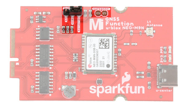
- SAFEBOOT - The PTH pads labeled as
SAFEBOOTis used to start up the IC in safe boot mode, this could be useful if you somehow manage to corrupt the module's Flash memory. Breakaway a row of 2-pins from the header, solder the pins to the board, and connect a 2-pin jumper to enable the mode.
 |
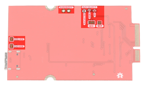 |
| Jumpers (Top View) | Jumpers (Bottom View) |
GPS Capabilities
The SparkFun GNSS Function Board NEO-M9N is able to connect to up to four different GNSS constellations at a time making it very accurate for its size. Below are the listed capabilities of the GPS unit when connecting to multiple GNSS constellations and when connecting to a single constellation.
| Constellations | GPS+GLO+GAL+BDS | GPS+GLONASS+GAL | GPS+GLO | GPS+BDS | GPS+GAL | |
|---|---|---|---|---|---|---|
| Horizontal Position Accuracy | 2m | 2m | 2m | 2m | 2m | |
| Max Navigation Update Rate | PVT | 25Hz | 25Hz | 25Hz | 25Hz | 25Hz |
| Time-To-First-Fix | Cold Start | 24s | 25s | 26s | 28s | 29s |
| Hot Start | 2s | 2s | 2s | 2s | 2s | |
| Sensitivity | Tracking and Navigation | -167dBm | -167dBm | -167dBm | -1667dBm | -166dBm |
| Reacquisition | -160dBm | -160dBm | -160dBm | -160dBm | -160dBm | |
| Cold Start | -148dBm | -148dBm | -148dBm | -148dBm | -148dBm | |
| Hot Start | -159dBm | -159dBm | -159dBm | -159dBm | -159dBm | |
| Velocity Accuracy | 0.05m/s | 0.05m/s | 0.05m/s | 0.05m/s | 0.05m/s | |
| Heading Accuracy | 0.3deg | 0.3deg | 0.3deg | 0.3deg | 0.3deg |
When using a single GNSS constellation:
| Constellation | GPS | GLONASS | BEIDOU | Galileo | |
|---|---|---|---|---|---|
| Horizontal Position Accuracy | 2m | 4m | 3m | 3m | |
| Max Navigation Update Rate | PVT | 25Hz | 25Hz | 25Hz | 25Hz |
| Time-To-First-Fix | Cold Start | 29s | 27s | 32s | 42s |
| Hot Start | 2s | 2s | 2s | 2s | |
| Sensitivity | Tracking and Navigation | -166dBm | -164dBm | -160dBm | -159dBm |
| Reacquisition | -160dBm | -155dBm | -157dBm | -154dBm | |
| Cold Start | -148dBm | -145dBm | -145dBm | -140dBm | |
| Hot Start | -159dBm | -156dBm | -159dBm | -154dBm | |
| Velocity Accuracy | 0.05m/s | 0.05m/s | 0.05m/s | 0.05m/s | |
| Heading Accuracy | 0.3deg | 0.3deg | 0.3deg | 0.3deg |
Hardware Pinout
Depending on your window size, you may need to use the horizontal scroll bar at the bottom of the table to view the additional pin functions. Note that the M.2 connector pins on opposing sides are offset from each other as indicated by the bottom pins where it says (Not Connected)*. There is no connection to pins that have a "-" under the primary function.
| AUDIO | UART | GPIO/BUS | I2C | SDIO | SPI0 | Dedicated |
| Function | Bottom Pin |
Top Pin |
Function | ||||||
|---|---|---|---|---|---|---|---|---|---|
| (Not Connected) | 75 | GND | |||||||
| 3.3V | 74 | 73 | G5 / BUS5 | ||||||
| RTC_3V_BATT | 72 | 71 | G6 / BUS6 | ||||||
| SPI_CS1# | SDIO_DATA3 (I/O) | 70 | 69 | G7 / BUS7 | |||||
| SDIO_DATA2 (I/O) | 68 | 67 | G8 | ||||||
| SDIO_DATA1 (I/O) | 66 | 65 | G9 | ADC_D- | CAM_HSYNC | ||||
| SPI_CIPO1 | SDIO_DATA0 (I/O) | 64 | 63 | G10 | ADC_D+ | CAM_VSYNC | |||
| SPI COPI1 | SDIO_CMD (I/O) | 62 | 61 | SPI_CIPO (I) | |||||
| SPI SCK1 | SDIO_SCK (O) | 60 | 59 | SPI_COPI (O) | LED_DAT | ||||
| AUD_MCLK (O) | 58 | 57 | SPI_SCK (O) | LED_CLK | |||||
| CAM_MCLK | PCM_OUT | I2S_OUT | AUD_OUT | 56 | 55 | SPI_CS# | |||
| CAM_PCLK | PCM_IN | I2S_IN | AUD_IN | 54 | 53 | I2C_SCL1 (I/O) | |||
| PDM_DATA | PCM_SYNC | I2S_WS | AUD_LRCLK | 52 | 51 | I2C_SDA1 (I/O) | |||
| PDM_CLK | PCM_CLK | I2S_SCK | AUD_BCLK | 50 | 49 | BATT_VIN / 3 (I - ADC) (0 to 3.3V) | |||
| G4 / BUS4 | 48 | 47 | PWM1 | ||||||
| G3 / BUS3 | 46 | 45 | GND | ||||||
| G2 / BUS2 | 44 | 43 | CAN_TX | ||||||
| G1 / BUS1 | 42 | 41 | CAN_RX | ||||||
| G0 / BUS0 | 40 | 39 | GND | ||||||
| A1 | 38 | 37 | USBHOST_D- | ||||||
| GND | 36 | 35 | USBHOST_D+ | ||||||
| A0 | 34 | 33 | GND | ||||||
| PWM0 | 32 | 31 | Module Key | ||||||
| Module Key | 30 | 29 | Module Key | ||||||
| Module Key | 28 | 27 | Module Key | ||||||
| Module Key | 26 | 25 | Module Key | ||||||
| Module Key | 24 | 23 | SWDIO | ||||||
| UART_TX2 (O) | 22 | 21 | SWDCK | ||||||
| UART_RX2 (I) | 20 | 19 | UART_RX1 (I) | ||||||
| CAM_TRIG | D1 | 18 | 17 | UART_TX1 (0) | |||||
| I2C_INT# | 16 | 15 | UART_CTS1 (I) | ||||||
| I2C_SCL (I/0) | 14 | 13 | UART_RTS1 (O) | ||||||
| I2C_SDA (I/0) | 12 | 11 | BOOT (I - Open Drain) | ||||||
| D0 | 10 | 9 | USB_VIN | ||||||
| SWO | G11 | 8 | 7 | GND | |||||
| RESET# (I - Open Drain) | 6 | 5 | USB_D- | ||||||
| 3.3V_EN | 4 | 3 | USB_D+ | ||||||
| 3.3V | 2 | 1 | GND | ||||||
| Function | Bottom Pin |
Top Pin |
Function | ||
|---|---|---|---|---|---|
| (Not Connected) | 75 | GND | |||
| VIN | 74 | 73 | 3.3V | ||
| VIN | 72 | 71 | Power EN | ||
| - | 70 | 69 | - | ||
| - | 66 | 65 | - | ||
| - | 64 | 63 | - | ||
| - | 62 | 61 | - | ||
| - | 60 | 59 | - | ||
| - | 58 | 57 | - | ||
| - | 56 | 55 | - | ||
| - | 54 | 53 | INT | ||
| - | 52 | 51 | RESET | ||
| - | 50 | 49 | SPI_CS0 | ||
| - | 48 | 47 | PPS | ||
| - | 46 | 45 | GND | ||
| - | 44 | 43 | - | ||
| - | 42 | 41 | - | ||
| EEPROM_WP | 40 | 39 | GND | ||
| - | 38 | 37 | - | ||
| EEEPROM_A0 | 36 | 35 | - | ||
| EEEPROM_A1 | 34 | 33 | GND | ||
| EEEPROM_A2 | 32 | 31 | Module Key | ||
| Module Key | 30 | 29 | Module Key | ||
| Module Key | 28 | 27 | Module Key | ||
| Module Key | 26 | 25 | Module Key | ||
| Module Key | 24 | 23 | - | ||
| - | 22 | 21 | I2C_SCL | ||
| - | 20 | 19 | I2C_SDA | ||
| - | 18 | 17 | - | ||
| - | 16 | 15 | UART_RX | ||
| - | 14 | 13 | UART_TX | ||
| - | 12 | 11 | - | ||
| - | 10 | 9 | - | ||
| - | 8 | 7 | SPI_SDO | ||
| - | 6 | 5 | SPI_SDI | ||
| - | 4 | 3 | SPI_SCK | ||
| - | 2 | 1 | GND | ||
| Signal Group | Signal | I/O | Description | Voltage | Power | 3.3V | I | 3.3V Source | 3.3V |
|---|---|---|---|---|
| GND | Return current path | 0V | ||
| USB_VIN | I | USB VIN compliant to USB 2.0 specification. Connect to pins on processor board that require 5V for USB functionality | 4.8-5.2V | |
| RTC_3V_BATT | I | 3V provided by external coin cell or mini battery. Max draw=100μA. Connect to pins maintaining an RTC during power loss. Can be left NC. | 3V | |
| 3.3V_EN | O | Controls the carrier board's main voltage regulator. Voltage above 1V will enable 3.3V power path. | 3.3V | |
| BATT_VIN/3 | I | Carrier board raw voltage over 3. 1/3 resistor divider is implemented on carrier board. Amplify the analog signal as needed for full 0-3.3V range | 3.3V | |
| Reset | Reset | I | Input to processor. Open drain with pullup on processor board. Pulling low resets processor. | 3.3V |
| Boot | I | Input to processor. Open drain with pullup on processor board. Pulling low puts processor into special boot mode. Can be left NC. | 3.3V | |
| USB | USB_D± | I/O | USB Data ±. Differential serial data interface compliant to USB 2.0 specification. If UART is required for programming, USB± must be routed to a USB-to-serial conversion IC on the processor board. | |
| USB Host | USBHOST_D± | I/O | For processors that support USB Host Mode. USB Data±. Differential serial data interface compliant to USB 2.0 specification. Can be left NC. | |
| CAN | CAN_RX | I | CAN Bus receive data. | 3.3V |
| CAN_TX | O | CAN Bus transmit data. | 3.3V | |
| UART | UART_RX1 | I | UART receive data. | 3.3V |
| UART_TX1 | O | UART transmit data. | 3.3V | |
| UART_RTS1 | O | UART ready to send. | 3.3V | |
| UART_CTS1 | I | UART clear to send. | 3.3V | |
| UART_RX2 | I | 2nd UART receive data. | 3.3V | |
| UART_TX2 | O | 2nd UART transmit data. | 3.3V | |
| I2C | I2C_SCL | I/O | I2C clock. Open drain with pullup on carrier board. | 3.3V |
| I2C_SDA | I/O | I2C data. Open drain with pullup on carrier board | 3.3V | |
| I2C_INT# | I | Interrupt notification from carrier board to processor. Open drain with pullup on carrier board. Active LOW | 3.3V | |
| I2C_SCL1 | I/O | 2nd I2C clock. Open drain with pullup on carrier board. | 3.3V | |
| I2C_SDA1 | I/O | 2nd I2C data. Open drain with pullup on carrier board. | 3.3V | |
| SPI | SPI_COPI | O | SPI Controller Output/Peripheral Input. | 3.3V |
| SPI_CIPO | I | SPI Controller Input/Peripheral Output. | 3.3V | |
| SPI_SCK | O | SPI Clock. | 3.3V | |
| SPI_CS# | O | SPI Chip Select. Active LOW. Can be routed to GPIO if hardware CS is unused. | 3.3V | |
| SPI/SDIO | SPI_SCK1/SDIO_CLK | O | 2nd SPI Clock. Secondary use is SDIO Clock. | 3.3V |
| SPI_COPI1/SDIO_CMD | I/O | 2nd SPI Controller Output/Peripheral Input. Secondary use is SDIO command interface. | 3.3V | |
| SPI_CIPO1/SDIO_DATA0 | I/O | 2nd SPI Peripheral Input/Controller Output. Secondary use is SDIO data exchange bit 0. | 3.3V | |
| SDIO_DATA1 | I/O | SDIO data exchange bit 1. | 3.3V | |
| SDIO_DATA2 | I/O | SDIO data exchange bit 2. | 3.3V | |
| SPI_CS1/SDIO_DATA3 | I/O | 2nd SPI Chip Select. Secondary use is SDIO data exchange bit 3. | 3.3V | |
| Audio | AUD_MCLK | O | Audio master clock. | 3.3V |
| AUD_OUT/PCM_OUT/I2S_OUT/CAM_MCLK | O | Audio data output. PCM synchronous data output. I2S serial data out. Camera master clock. | 3.3V | |
| AUD_IN/PCM_IN/I2S_IN/CAM_PCLK | I | Audio data input. PCM syncrhonous data input. I2S serial data in. Camera periphperal clock. | 3.3V | |
| AUD_LRCLK/PCM_SYNC/I2S_WS/PDM_DATA | I/O | Audio left/right clock. PCM syncrhonous data SYNC. I2S word select. PDM data. | 3.3V | |
| AUD_BCLK/PCM_CLK/I2S_CLK/PDM_CLK | O | Audio bit clock. PCM clock. I2S continuous serial clock. PDM clock. | 3.3V | |
| SWD | SWDIO | I/O | Serial Wire Debug I/O. Connect if processor board supports SWD. Can be left NC. | 3.3V |
| SWDCK | I | Serial Wire Debug clock. Connect if processor board supports SWD. Can be left NC. | 3.3V | |
| ADC | A0 | I | Analog to digital converter 0. Amplify the analog signal as needed to enable full 0-3.3V range. | 3.3V |
| A1 | I | Analog to digital converter 1. Amplify the analog signal as needed to enable full 0-3.3V range. | 3.3V | |
| PWM | PWM0 | O | Pulse width modulated output 0. | 3.3V |
| PWM1 | O | Pulse width modulated output 1. | 3.3V | |
| Digital | D0 | I/O | General digital input/output pin. | 3.3V |
| D1/CAM_TRIG | I/O | General digital input/output pin. Camera trigger. | 3.3V | |
| General/Bus | G0/BUS0 | I/O | General purpose pins. Any unused processor pins should be assigned to Gx with ADC + PWM capable pins given priority (0, 1, 2, etc.) positions. The intent is to guarantee PWM, ADC and Digital Pin functionality on respective ADC/PWM/Digital pins. Gx pins do not guarantee ADC/PWM function. Alternative use is pins can support a fast read/write 8-bit or 4-bit wide bus. | 3.3V |
| G1/BUS1 | I/O | 3.3V | ||
| G2/BUS2 | I/O | 3.3V | ||
| G3/BUS3 | I/O | 3.3V | ||
| G4/BUS4 | I/O | 3.3V | ||
| G5/BUS5 | I/O | 3.3V | ||
| G6/BUS6 | I/O | 3.3V | ||
| G7/BUS7 | I/O | 3.3V | ||
| G8 | I/O | General purpose pin | 3.3V | |
| G9/ADC_D-/CAM_HSYNC | I/O | Differential ADC input if available. Camera horizontal sync. | 3.3V | |
| G10/ADC_D+/CAM_VSYNC | I/O | Differential ADC input if available. Camera vertical sync. | 3.3V | |
| G11/SWO | I/O | General purpose pin. Serial Wire Output | 3.3V |
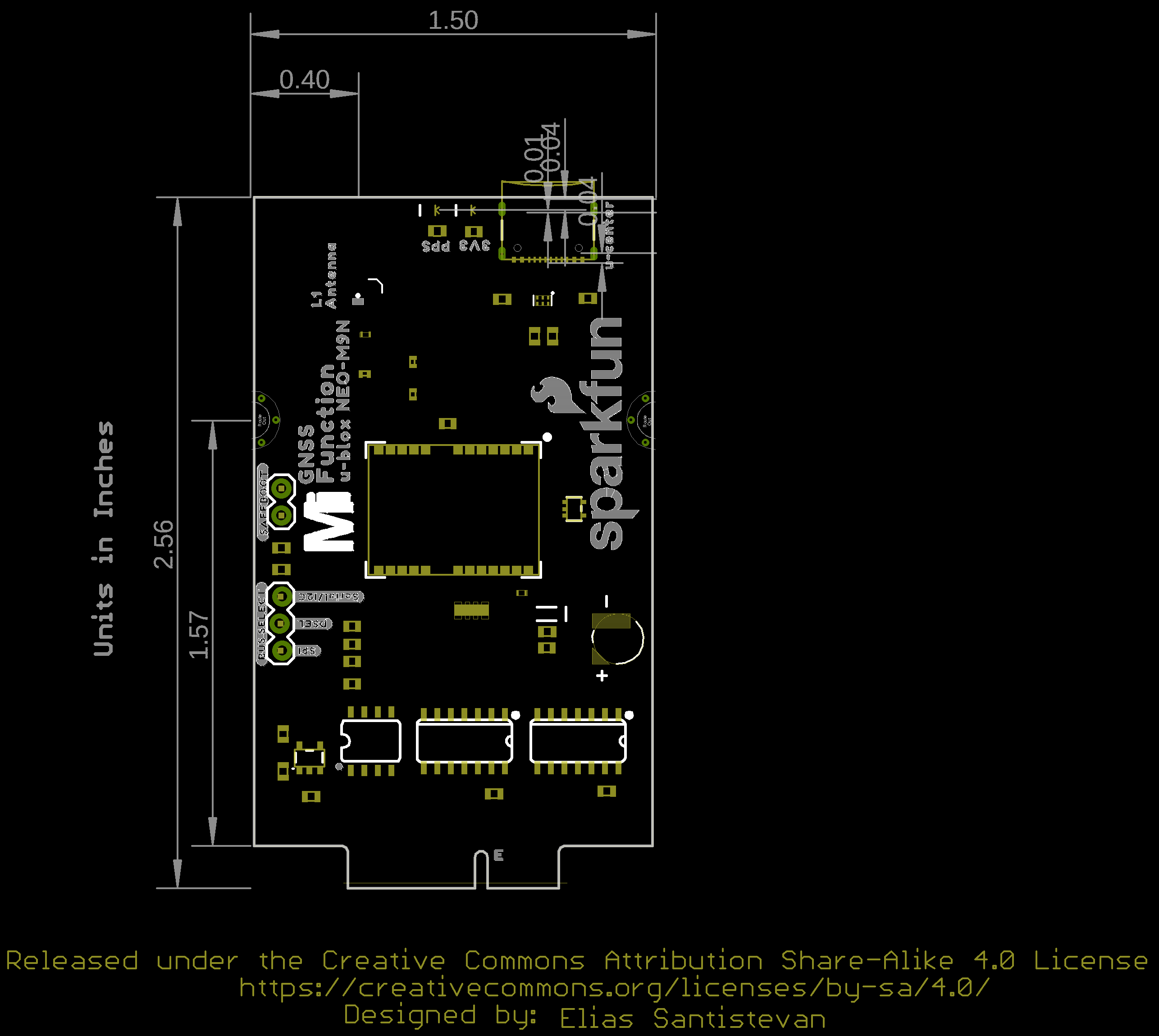
Board Dimensions
The board uses the standard MicroMod Function Board size which measures about 1.50"x2.56".
Hardware Assembly
If you have not already, make sure to check out the Getting Started with MicroMod: Hardware Hookup for information on inserting your Processor and Function Boards to the Main Board.
Getting Started with MicroMod
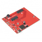
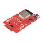
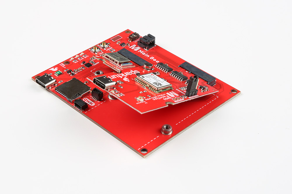
Insert your chosen Processor and GNSS Function board at an angle into the M.2 connector. The Processor Board will stick up at an angle (at around 25°).
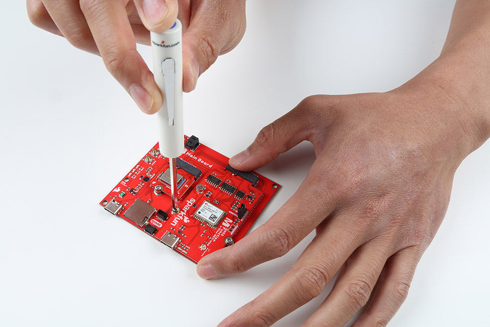
Hold down each board, insert the screws, and to tighten.
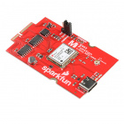
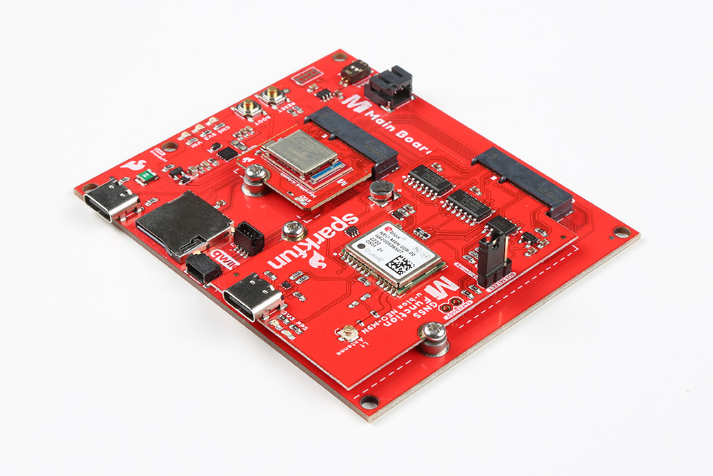
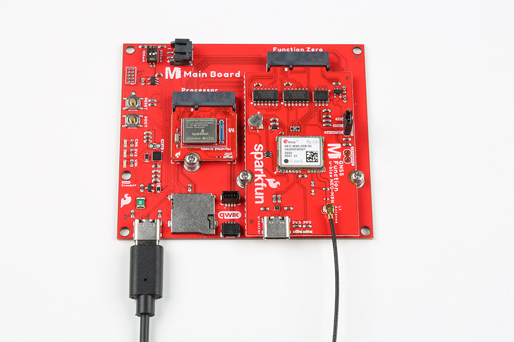
After securing the Processor and Function Board to the Main Board, your setup should look like the image below.
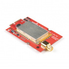
Insert the u.FL adapter to the MicroMod GNSS Function Board. Connect the patch antenna to the other end of the u.FL adapter. The SMA connector just needs to be finger tight to secure the antenna to the adapter..
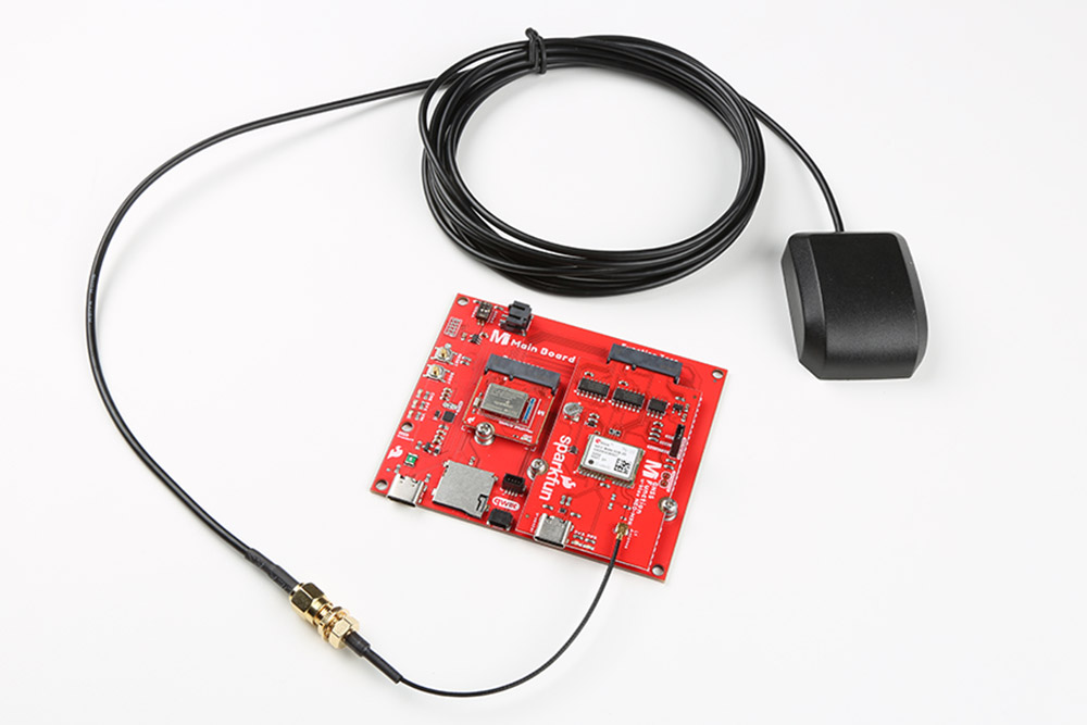
Connect a USB Type C Cable to power and program your Processor Board. In this case, we used the MicroMod Main Board - Single and MicroMod Artemis Processor. This will also power the MicroMod GNSS Function Board.
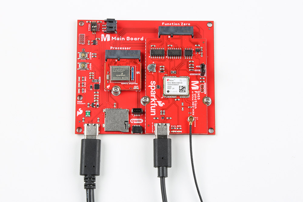
For users that want to connect the NEO-M9N to u-blox's u-center, insert a second USB Type C cable to the MicroMod GNSS Function Board's USB C connector.
Software Installation
Arduino Board Definitions and Driver
We'll assume that you installed the necessary board files and drivers for your Processor Board. In this case, we used the MicroMod Artemis Processor Board which uses the CH340 USB-to-serial converter. If you are using a Processor Board, make sure to check out its hookup guide for your Processor Board.
Installing Board Definitions in the Arduino IDE
MicroMod Artemis Processor Board Hookup Guide
How to Install CH340 Drivers
Arduino Library
All of our u-blox based GPS boards share the same library: this board, their predeccesors and the higher precision u-blox cousins. The SparkFun u-blox Arduino library can be downloaded with the Arduino library manager by searching 'SparkFun u-blox GNSS' or you can grab the zip here from the GitHub repository to manually install:
There are several example sketches provided that utilize the I2C bus to get you up and receiving messages from space. We'll go over one of the examples in this tutorial.
Main Board Example - Pin Connection Table
For NEO-M9N specific pins, here is the mapping between the function board and main board's processor pins. For the following examples, we are using the Artemis Processor Board.
| AUDIO | UART | GPIO/BUS | I2C | SDIO | SPI | Dedicated |
|
NEO-M9N Function Board
Pin Name |
I/O
Direction |
Main Board's
Processor Pin |
Slot 0 | Slot 1 |
|---|---|---|---|
| VCC | I | VCC | VCC |
| EN | O | PWR_EN0 | PWR_EN1 |
| GND | - | GND | GND |
| SPI_SCK | O | SPI_SCK | SPI_SCK |
| SPI_POCI | I | SPI_POCI | SPI_POCI |
| SPI_PICO | O | SPI_PICO | SPI_PICO |
| I2C_SCL | I/O | I2C_SCL | I2C_SCL |
| I2C_SDA | I/O | I2C_SDA | I2C_SDA |
| RX | O | TX1 | TX2 |
| TX | I | RX1 | RX2 |
| PPS | I/O | D0 | D1 |
| SPI_CS | I/O | CS0 | CS1 |
| RESET | I/O | PWM0 | PWM1 |
| INT | I/O | G0 | G5 |
| EEPROM_A0 | I/O | - | - |
| EEPROM_A1 | I/O | - | - |
| EEPROM_A2 | I/O | - | - |
| EEPROM_WP | I/O | - | - |
Arduino Example
We're just going to look at example two (i.e. "Example2_NMEAParsing.ino") which in my opinion, makes it clear the awesomeness of these GPS receivers. That is to say, talking to satellites and finding out where in the world you are.
language:c
#include <Wire.h> //Needed for I2C to GPS

#include "SparkFun_u-blox_GNSS_Arduino_Library.h" //Click here to get the library: http://librarymanager/All#SparkFun_u-blox_GNSS
SFE_UBLOX_GNSS myGNSS;

void setup()
{
  Serial.begin(115200);
  Serial.println("SparkFun u-blox Example");

  Wire.begin();

  if (myGNSS.begin() == false)
  {
    Serial.println(F("u-blox GNSS module not detected at default I2C address. Please check wiring. Freezing."));
    while (1);
  }

  //This will pipe all NMEA sentences to the serial port so we can see them
  myGNSS.setNMEAOutputPort(Serial);
}

void loop()
{
  myGNSS.checkUblox(); //See if new data is available. Process bytes as they come in.

  delay(250); //Don't pound too hard on the I2C bus
}
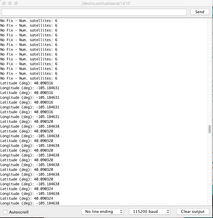
When you upload this code you'll have to wait ~24s to get a lock onto any satellites. After that first lock, the backup battery on the board will provide power to some internal systems that will allow for a hot start the next time you turn on the board. The hot start only lasts four hours, but allows you to get a lock within one second. After you get a lock the serial terminal will start listing longitude and latitude coordinates, as seen below. Make sure to set the serial monitor to 115200 baud.
Troubleshooting
If you need technical assistance and more information on a product that is not working as you expected, we recommend heading on over to the SparkFun Technical Assistance page for some initial troubleshooting.
If you don't find what you need there, the SparkFun Forums are a great place to find and ask for help. If this is your first visit, you'll need to create a Forum Account to search product forums and post questions.
Resources and Going Further
Ready to get hands-on with GPS?
We've got a page just for you! We'll walk you through the basics of how GPS works, the hardware needed, and project tutorials to get you started.
Now that you've successfully got your MicroMod GNSS Function Board - NEO-M9N up and running, it's time to incorporate it into your own project! For more information, check out the resources below.
Hardware Documentation
- Schematic (PDF)
- Eagle Files (ZIP)
- Board Dimensions (PNG)
- Building a GPS System
- u-blox NEO-M9N Documents & Resources
- SparkFun u-blox GNSS Arduino Library
- GitHub Hardware Repo
- SFE Product Showcase
MicroMod Documentation
Or check out other tutorials related to GPS and GNSS: