Arduino Weather Shield Hookup Guide V12
 Nate, santaimpersonator,
  SparkFro
 Introduction
Heads up! This is for the Arduino Weather Shield v12 [DEV-13956] that uses the Si7021. If you are looking at the older version of the weather shield, you should check out the older tutorial for DEV-12081 that uses the HTU21D.
Updated Content: This guide was updated on 7/5/23.
- The Weather Station and Weather Station with GPS firmware were modified to utilize our new SparkFun Weather Meter Kit Arduino library
- A few of the parts and instructions, were also updated to account for any retired components, outdated information, etc.
- Please note, this shield is currently not compatible with the new Arduino Uno (R4). There is an issue with the values returned from the Arduino libraries for the I2C sensors (temperature, humidity, and pressure).
Library Versions:
While this tutorial and its example code were recently updated, this was before the lastest release of the SparkFun Si7021 Arduino library. The latest release is not backwards compatible and will create compilation issues with the existing example code for this hookup guide. Therefore, we recommend users only utilize these specific version of these libraries, until we have a more permanent fix:
- SparkFun Si7021 Arduino Library v1.0.5
- SparkFun External MPL3115A2 Arduino Library v1.2.4
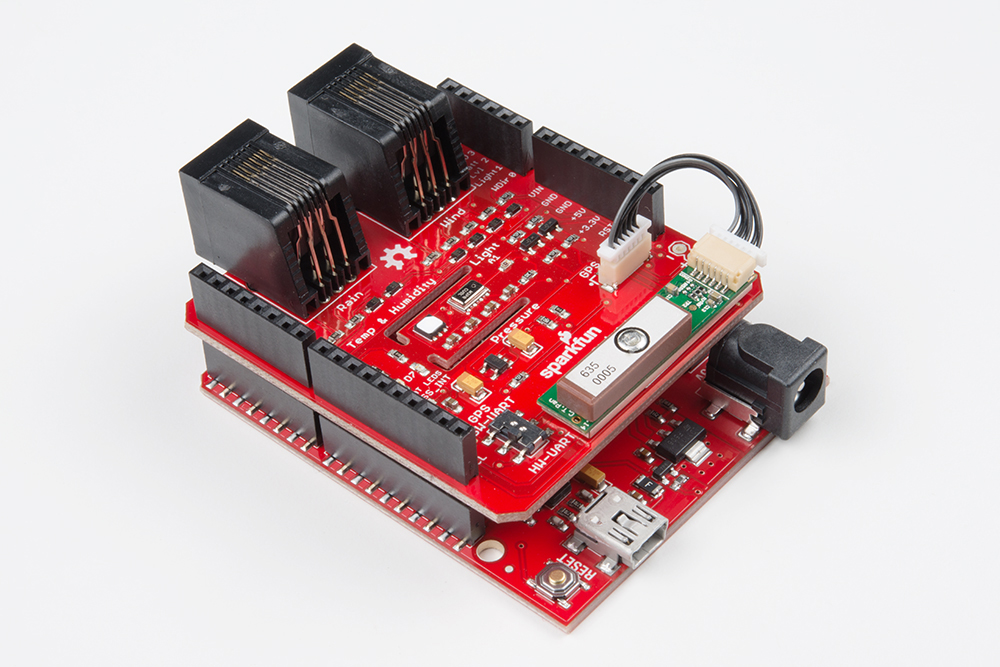
The Arduino Weather Shield from SparkFun is an easy-to-use Arduino shield that grants you access to barometric pressure, relative humidity, luminosity, and temperature. There are also connections to optional sensors such as wind speed/direction, rain gauge, and GPS for location and super accurate timing.
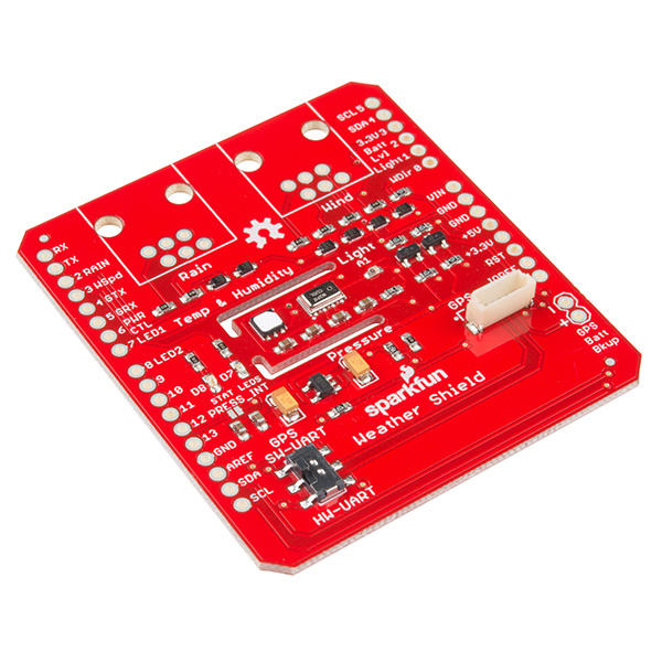
SparkFun Weather Shield
DEV-13956Things you should know about this shield:
- Uses the Si7021 sensor, MPL3115A2 barometric pressure sensor, and ALS-PT19 light sensor.
- Has a 6-pin JST connector for the GP-735 compact GPS module
- Has optional RJ11 connector footprints to connect the SparkFun weather meter kit
- Weather shield can operate from 3V to 10V and has built in voltage regulators and signal translators
- When utilized with the Weather Meter Kit, the shield must be used with a 5V board (i.e. RedBoard, Arduino Uno (R3), etc.) for compatibility with the wind vane data.
- The new Arduino Uno (R4) is not compatible with the Arduino libraries of the I2C sensors and is not recommended to use with the shield.
- Typical humidity accuracy of ±2%
- Typical pressure accuracy of ±50Pa
- Typical temperature accuracy of ±0.3C
Required Materials
To get up and running with the Weather Shield you'll need the following parts:
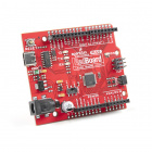
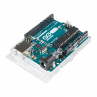
- Arduino Uno (R3), RedBoard, or other compatible board
- Compatible USB cable
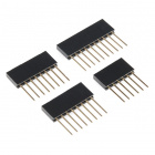
- Arduino Stackable Headers
- Soldering Tools


Related Accessories
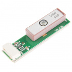
- GP-735 GPS Module and
1.75" mating cable- The shorter 1.75" JST cable has been retired; however, our 1ft. 6-pin JST cable is still available
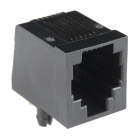
- Two RJ11 6-pin Connectors
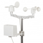
- Weather Meter Kit
Suggested Reading
If you are unfamiliar with any of the concepts below, we suggest checking out these tutorials.
How to Solder: Through-Hole Soldering
Serial Communication
Installing an Arduino Library
Arduino Shields v2
Check out our hookup guides for more information about the temperature/humidity and pressure sensors on the shield. If you intend to collect wind and rain data, assembly instructions for the Weather Meter Kit can be found in our Weather Meter Assembly Guide.
GPS Basics
MPL3115A2 Pressure Sensor Hookup Guide
Si7021 Humidity and Temperature Sensor Hookup Guide
Weather Meter Hookup Guide
To understand how the libraries of the associated sensors work, we recommend the following tutorials.
Pull-up Resistors
Analog to Digital Conversion
I2C
Processor Interrupts with Arduino
Hardware Assembly
Note: Users who are unfamiliar with Arduino shields or soldering, should review the following tutorials:
How to Solder: Through-Hole Soldering
Arduino Shields v2
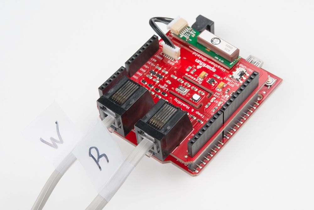
Solder the stackable headers onto the shield, and insert the shield into your Arduino. You are welcome to solder in the RJ11 connectors to the top of the board as well. If you have the GP-735 GPS module, don't worry about attaching it at this time, we'll get to GPS later.
Software Overview
Installing an Arduino Library
Installing Arduino IDE
How to Install FTDI Drivers
How to Install CH340 Drivers
Firmware for Examples
All the example code for this tutorial, can be downloaded the GitHub Repository of the Weather shield:
Arduino Libraries
To utilize the example firmware, users will need to install and configure the Arduino libraries for the following components.
On Board Sensors
The firmware examples below rely on the SparkFun Si7021 and MPL3115A2 Arduino libraries. These libraries can be installed through the Arduino Library Manager. Search for SparkFun MPL3115 and SparkFun Si7021 to install the latest version. The libraries can also be manually downloaded from their GitHub repository:
or utilize the buttons below:
Library Versions: This tutorial and its example code were recently updated; however, this was before the lastest release of the SparkFun Si7021 Arduino library. This latest release is not backwards compatible and will create compilation issues with the existing example code for this hookup guide. Therefore, we recommend users only utilize these specific version of these libraries, until we have a more permanent fix:
- SparkFun Si7021 Arduino Library v1.0.5
- SparkFun External MPL3115A2 Arduino Library v1.2.4
For more details on these sensors and their Arduino libraries, please refer to the hookup guides of their breakout boards:
MPL3115A2 Pressure Sensor Hookup Guide
Si7021 Humidity and Temperature Sensor Hookup Guide
Weather Meter Kit
We've written an Arduino library for users to easily setup and read data from the SparkFun Weather Meter Kit. The library can be installed through the Arduino Library Manager; search for SparkFun Weather Meter Kit to install the latest version. Users can also manually download the library from the GitHub repository or by clicking the button below:
Configuration
The SparkFun Weather Meter Kit Arduino library was originally written to be used with the ESP32 MicroMod Processor and MicroMod Weather Carrier board. Therefore, it assumes certain electrical and microcontroller constraints when reading the wind vane direction. To utilize this library with this tutorial, users will need to make the following modifications:
- In the
SparkFun_Weather_Meter_Kit_Arduino_Library.cppfile of the library (located in thesrcfolder), users will need to modify the file by commenting out lines 26-41 and enabling lines 45-60. This modifies the expected ADC values for the wind vane direction. The library assumes that a 12-bit ADC is connected to the weather vane. This can be modified through the library for boards like the Arduino Uno or RedBoard, which have a 10-bit ADC.
In the
setup()loop, specify the ADC resolution; where<ADC resolution>should be an integer value of the microcontroller's ADC resolution in bits:setADCResolutionBits(<ADC resolution>);
Users will also need to declare the electrical connections from the Weather shield to the sensors of Weather Meter Kit
const byte WSPEED = 3;
const byte RAIN = 2;
const byte WDIR = A0;
GPS Module
In order to interpret the NMEA sentences from the GPS module, the firmware below relies on the TinyGPSPlus Arduino library, written by Mikal Hart. The library can be installed through the Arduino Library Manager; search for TinyGPSPlus to install the latest version. Users can also manually download the library from the GitHub repository or by clicking the button below:
For more details about the TinyGPSPlus Arduino library, please refer this blog post on Arduiniana.
Configuration
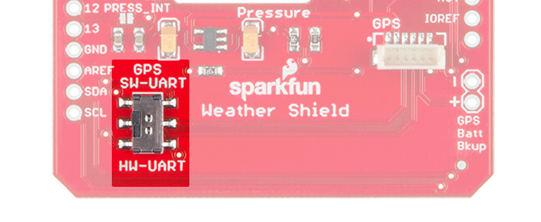
When the switch on the Weather shield toggled to SW-UART, the TinyGPSPlus Arduino library will need to utilize the SoftwareSerial Arduino library. In order to parse the data, users will need to declare the electrical connections from the Weather shield to the GPS module.
When the switch is toggled to SW-UART, the RX and TX pins of the GP-735 GPS module are:
language:c
static const int RXPin = 5, TXPin = 4;
Note: When the switch is toggled to HW-UART, the RX and TX pins of the GP-735 GPS module are:
static const int RXPin = 0, TXPin = 1;
Users will also need to declare the baud rate of the GP-735 GPS module.
language:c
static const uint32_t GPSBaud = 9600;
In the firmware, users will need to include and create an instance for the the SoftwareSerial Arduino library. Then, the baud rate will need be configured in the setup() loop for the GPS module:
language:c
#include <SoftwareSerial.h>       //Needed for GPS
SoftwareSerial ss(RXPin, TXPin);
language:c ss.begin(GPSBaud);
Example Firmware - Basic
Before uploading code to your Arduino with the Weather Shield attached, make sure the GPS UART switch is in the SW-UART position. Having the switch in the opposite position connects the GPS lines to the USB lines and may cause errors while uploading.
Open the Weather_Shield_Basic_V12.ino sketch from the Firmware folder or copy and paste the code below into the Arduino IDE:
language:c
/*
 Weather Shield Example
 By: Nathan Seidle
 SparkFun Electronics
 Date: June 10th, 2016
 License: This code is public domain but you buy me a beer if you use this and we meet someday (Beerware license).

 This example prints the current humidity, air pressure, temperature and light levels.

 The weather shield is capable of a lot. Be sure to checkout the other more advanced examples for creating
 your own weather station.

 Updated by Joel Bartlett
 03/02/2017
 Removed HTU21D code and replaced with Si7021
 */

#include <Wire.h> //I2C needed for sensors
#include "SparkFunMPL3115A2.h" //Pressure sensor - Search "SparkFun MPL3115" and install from Library Manager
#include "SparkFun_Si7021_Breakout_Library.h" //Humidity sensor - Search "SparkFun Si7021" and install from Library Manager

MPL3115A2 myPressure; //Create an instance of the pressure sensor
Weather myHumidity;//Create an instance of the humidity sensor

//Hardware pin definitions
//-=-=-=-=-=-=-=-=-=-=-=-=-=-=-=-=-=-=-=-=-=-=-=-=-=-=-=-=
const byte STAT_BLUE = 7;
const byte STAT_GREEN = 8;

const byte REFERENCE_3V3 = A3;
const byte LIGHT = A1;
const byte BATT = A2;

//Global Variables
//-=-=-=-=-=-=-=-=-=-=-=-=-=-=-=-=-=-=-=-=-=-=-=-=-=-=-=-=
long lastSecond; //The millis counter to see when a second rolls by

void setup()
{
  Serial.begin(9600);
  Serial.println("Weather Shield Example");

  pinMode(STAT_BLUE, OUTPUT); //Status LED Blue
  pinMode(STAT_GREEN, OUTPUT); //Status LED Green

  pinMode(REFERENCE_3V3, INPUT);
  pinMode(LIGHT, INPUT);

  //Configure the pressure sensor
  myPressure.begin(); // Get sensor online
  myPressure.setModeBarometer(); // Measure pressure in Pascals from 20 to 110 kPa
  myPressure.setOversampleRate(7); // Set Oversample to the recommended 128
  myPressure.enableEventFlags(); // Enable all three pressure and temp event flags

  //Configure the humidity sensor
  myHumidity.begin();

  lastSecond = millis();

  Serial.println("Weather Shield online!");
}

void loop()
{
  //Print readings every second
  if (millis() - lastSecond >= 1000)
  {
    digitalWrite(STAT_BLUE, HIGH); //Blink stat LED

    lastSecond += 1000;

    //Check Humidity Sensor
    float humidity = myHumidity.getRH();

    if (humidity == 998) //Humidty sensor failed to respond
    {
      Serial.println("I2C communication to sensors is not working. Check solder connections.");

      //Try re-initializing the I2C comm and the sensors
      myPressure.begin();
      myPressure.setModeBarometer();
      myPressure.setOversampleRate(7);
      myPressure.enableEventFlags();
      myHumidity.begin();
    }
    else
    {
      Serial.print("Humidity = ");
      Serial.print(humidity);
      Serial.print("%,");
      float temp_h = myHumidity.getTempF();
      Serial.print(" temp_h = ");
      Serial.print(temp_h, 2);
      Serial.print("F,");

      //Check Pressure Sensor
      float pressure = myPressure.readPressure();
      Serial.print(" Pressure = ");
      Serial.print(pressure);
      Serial.print("Pa,");

      //Check tempf from pressure sensor
      float tempf = myPressure.readTempF();
      Serial.print(" temp_p = ");
      Serial.print(tempf, 2);
      Serial.print("F,");

      //Check light sensor
      float light_lvl = get_light_level();
      Serial.print(" light_lvl = ");
      Serial.print(light_lvl);
      Serial.print("V,");

      //Check batt level
      float batt_lvl = get_battery_level();
      Serial.print(" VinPin = ");
      Serial.print(batt_lvl);
      Serial.print("V");

      Serial.println();
    }

    digitalWrite(STAT_BLUE, LOW); //Turn off stat LED
  }

  delay(100);
}

//Returns the voltage of the light sensor based on the 3.3V rail
//This allows us to ignore what VCC might be (an Arduino plugged into USB has VCC of 4.5 to 5.2V)
float get_light_level()
{
  float operatingVoltage = analogRead(REFERENCE_3V3);

  float lightSensor = analogRead(LIGHT);

  operatingVoltage = 3.3 / operatingVoltage; //The reference voltage is 3.3V

  lightSensor = operatingVoltage * lightSensor;

  return (lightSensor);
}

//Returns the voltage of the raw pin based on the 3.3V rail
//This allows us to ignore what VCC might be (an Arduino plugged into USB has VCC of 4.5 to 5.2V)
//Battery level is connected to the RAW pin on Arduino and is fed through two 5% resistors:
//3.9K on the high side (R1), and 1K on the low side (R2)
float get_battery_level()
{
  float operatingVoltage = analogRead(REFERENCE_3V3);

  float rawVoltage = analogRead(BATT);

  operatingVoltage = 3.30 / operatingVoltage; //The reference voltage is 3.3V

  rawVoltage = operatingVoltage * rawVoltage; //Convert the 0 to 1023 int to actual voltage on BATT pin

  rawVoltage *= 4.90; //(3.9k+1k)/1k - multiple BATT voltage by the voltage divider to get actual system voltage

  return (rawVoltage);
}
Open the Serial Monitor. You should see the following output:
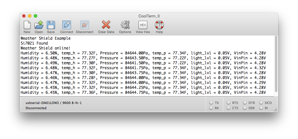
Put your hand over the small clear device labeled 'Light', and watch the light level change to 0. Blow lightly on the humidity sensor, and watch the humidity change.
Example Firmware - Weather Station
For the more adventurous, check out the Weather_Shield_Weather_Station_V12.ino sketch. This code demonstrates shield's capabilities to collect weather data, when a weather meter kit is connected:
language:c
/*
  Weather Shield Example
  By: Nathan Seidle
  SparkFun Electronics
  Date: November 16th, 2013
  License: This code is public domain but you buy me a beer if you use this and we meet someday (Beerware license).

  Much of this is based on Mike Grusin's USB Weather Board code: https://www.sparkfun.com/products/10586

  This is a more advanced example of how to utilize every aspect of the weather shield. See the basic
  example if you're just getting started.

  This code reads all the various sensors (wind speed, direction, rain gauge, humidity, pressure, light, batt_lvl)
  and reports it over the serial comm port. This can be easily routed to a datalogger (such as OpenLog) or
  a wireless transmitter (such as Electric Imp).

  Measurements are reported once a second but windspeed and rain gauge are tied to interrupts that are
  calculated at each report.

  This example code assumes the GPS module is not used.

  Updated by Joel Bartlett
  03/02/2017
  Removed HTU21D code and replaced with Si7021

  Updated be Wes Furuya
  06/19/2023
  Implemented "Weather Meter" Arduino library
*/

#include <Wire.h>                                        //I2C needed for sensors
#include "SparkFunMPL3115A2.h"                           //Pressure sensor - Search "SparkFun MPL3115" and install from Library Manager
#include "SparkFun_Si7021_Breakout_Library.h"            //Humidity sensor - Search "SparkFun Si7021" and install from Library Manager
#include "SparkFun_Weather_Meter_Kit_Arduino_Library.h"  //Weather meter kit - Search "SparkFun Weather Meter" and install from Library Manager


//Hardware pin definitions
//-=-=-=-=-=-=-=-=-=-=-=-=-=-=-=-=-=-=-=-=-=-=-=-=-=-=-=-=
// digital I/O pins
const byte WSPEED = 3;
const byte RAIN = 2;
const byte STAT1 = 7;
const byte STAT2 = 8;

// analog I/O pins
const byte REFERENCE_3V3 = A3;
const byte LIGHT = A1;
const byte BATT = A2;
const byte WDIR = A0;
//-=-=-=-=-=-=-=-=-=-=-=-=-=-=-=-=-=-=-=-=-=-=-=-=-=-=-=-=

//Global Variables
//-=-=-=-=-=-=-=-=-=-=-=-=-=-=-=-=-=-=-=-=-=-=-=-=-=-=-=-=
long lastSecond;  //The millis counter to see when a second rolls by

float humidity = 0;  // [%]
float tempf = 0;     // [temperature F]
//float baromin = 30.03;// [barom in] - It's hard to calculate baromin locally, do this in the agent
float pressure = 0;

float wind_dir = 0;    // [degrees (Cardinal)]
float wind_speed = 0;  // [kph]
float rain = 0;        // [mm]

float batt_lvl = 11.8;  //[analog value from 0 to 1023]
float light_lvl = 455;  //[analog value from 0 to 1023]
//-=-=-=-=-=-=-=-=-=-=-=-=-=-=-=-=-=-=-=-=-=-=-=-=-=-=-=-=


MPL3115A2 myPressure;                                      //Create an instance of the pressure sensor
Weather myHumidity;                                        //Create an instance of the humidity sensor
SFEWeatherMeterKit myweatherMeterKit(WDIR, WSPEED, RAIN);  // Create an instance of the weather meter kit


void setup() {
  Serial.begin(115200);
  Serial.println("Weather Shield Example");

  pinMode(STAT1, OUTPUT);  //Status LED Blue
  pinMode(STAT2, OUTPUT);  //Status LED Green

  // pinMode(WSPEED, INPUT_PULLUP); // input from wind meters windspeed sensor
  // pinMode(RAIN, INPUT_PULLUP); // input from wind meters rain gauge sensor

  pinMode(REFERENCE_3V3, INPUT);
  pinMode(LIGHT, INPUT);

  //Configure the pressure sensor
  myPressure.begin();               // Get sensor online
  myPressure.setModeBarometer();    // Measure pressure in Pascals from 20 to 110 kPa
  myPressure.setOversampleRate(7);  // Set Oversample to the recommended 128
  myPressure.enableEventFlags();    // Enable all three pressure and temp event flags

  //Configure the humidity sensor
  myHumidity.begin();

  // The weather meter kit library assumes a 12-bit ADC
  // Configuring a 10-bit ADC resolution for the ATmega328 (RedBoard/Uno)
  myweatherMeterKit.setADCResolutionBits(10);

  // Begin weather meter kit
  myweatherMeterKit.begin();

  lastSecond = millis();

  // // attach external interrupt pins to IRQ functions
  // attachInterrupt(0, rainIRQ, FALLING);
  // attachInterrupt(1, wspeedIRQ, FALLING);

  // // turn on interrupts
  // interrupts();

  Serial.println("Weather Shield online!");
}

void loop() {
  //Keep track of which minute it is
  if (millis() - lastSecond >= 1000) {
    digitalWrite(STAT1, HIGH);  //Blink stat LED

    lastSecond += 1000;

    //Report all readings every second
    printWeather();
  }

  digitalWrite(STAT1, LOW);  //Turn off stat LED

  delay(100);
}

//Calculates each of the variables that wunderground is expecting
void calcWeather() {

  //Calc temp/humidity from Si7021 sensor
  humidity = myHumidity.getRH();
  tempf = myHumidity.readTempF();

  //Weather Meter Kit
  //Calc Wind
  wind_dir = myweatherMeterKit.getWindDirection();
  wind_speed = myweatherMeterKit.getWindSpeed();
  //Calc Rain
  rain = myweatherMeterKit.getTotalRainfall();

  //Calc pressure from MPL3115A2
  pressure = myPressure.readPressure();

  //Calc light level
  light_lvl = get_light_level();

  //Calc battery level
  batt_lvl = get_battery_level();
}

//Returns the voltage of the light sensor based on the 3.3V rail
//This allows us to ignore what VCC might be (an Arduino plugged into USB has VCC of 4.5 to 5.2V)
float get_light_level() {
  float operatingVoltage = analogRead(REFERENCE_3V3);

  float lightSensor = analogRead(LIGHT);

  operatingVoltage = 3.3 / operatingVoltage;  //The reference voltage is 3.3V

  lightSensor = operatingVoltage * lightSensor;

  return (lightSensor);
}

//Returns the voltage of the raw pin based on the 3.3V rail
//This allows us to ignore what VCC might be (an Arduino plugged into USB has VCC of 4.5 to 5.2V)
//Battery level is connected to the RAW pin on Arduino and is fed through two 5% resistors:
//3.9K on the high side (R1), and 1K on the low side (R2)
float get_battery_level() {
  float operatingVoltage = analogRead(REFERENCE_3V3);

  float rawVoltage = analogRead(BATT);

  operatingVoltage = 3.30 / operatingVoltage;  //The reference voltage is 3.3V

  rawVoltage = operatingVoltage * rawVoltage;  //Convert the 0 to 1023 int to actual voltage on BATT pin

  rawVoltage *= 4.90;  //(3.9k+1k)/1k - multiple BATT voltage by the voltage divider to get actual system voltage

  return (rawVoltage);
}


//Prints the various variables directly to the port
//I don't like the way this function is written but Arduino doesn't support floats under sprintf
void printWeather() {
  calcWeather();  //Go calc all the various sensors

  Serial.println();
  Serial.print("humidity=");
  Serial.print(humidity, 1);
  Serial.print(" %RH, tempf=");
  Serial.print(tempf, 1);
  Serial.print(" F, pressure=");
  Serial.print(pressure, 2);
  Serial.print(" Pa, wind direction= ");
  Serial.print(wind_dir, 1);
  Serial.print(" deg, wind speed= ");
  Serial.print(wind_speed, 1);
  Serial.print(" kph, total rain= ");
  Serial.print(rain, 1);
  Serial.print(" mm, batt_lvl=");
  Serial.print(batt_lvl, 2);
  Serial.print(" V, light_lvl=");
  Serial.print(light_lvl, 2);
  Serial.print(",");
  Serial.println("#");
}
Upload the sketch onto your board and open the serial monitor at 115200 bps. You should see output similar to the following:
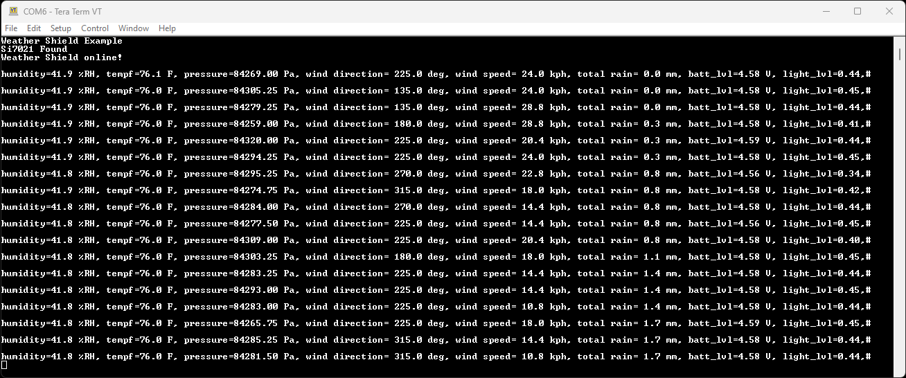
Example Firmware - Weather Station with GPS
Attach the GP-735 GPS module using a JST cable. To secure the module, there is space on the shield to attach the module using double-stick tape.
There is a switch labeled Serial on the shield. This is to select which pins on the Arduino to connect the GPS to. In almost all cases the switch should be set to 'Soft'. This will attach the GPS serial pins to digital pins 5 (TX from the GPS) and 4 (RX into the GPS).
Grab the GPS example sketch from the GitHub repo that demonstrates using the GP-735 with all the other sensors. Load it onto your Arduino, and open the serial monitor at 115200 bps.
You can also copy the code below:
language:c
/*
  Weather Shield Example
  By: Nathan Seidle
  SparkFun Electronics
  Date: November 16th, 2013
  License: This code is public domain but you buy me a beer if you use this and we meet someday (Beerware license).

  Much of this is based on Mike Grusin's USB Weather Board code: https://www.sparkfun.com/products/10586

  This code reads all the various sensors (wind speed, direction, rain gauge, humidity, pressure, light, batt_lvl, GPS data)
  and reports it over the serial comm port. This can be easily routed to a datalogger (such as OpenLog) or
  a wireless transmitter (such as Electric Imp).

  Measurements are reported once a second. The windspeed and rain gauge are tied to interrupts and are
  calculated at the instance of each report.

  This example code assumes the GP-735 GPS module is attached.

  Updated by Joel Bartlett
  03/02/2017
  Removed HTU21D code and replaced with Si7021

  Updated be Wes Furuya
  06/19/2023
  Implemented "Weather Meter" Arduino library
  Updated to TinyGPSPlus Arduino library
*/

#include <Wire.h>                                        //I2C needed for sensors
#include "SparkFunMPL3115A2.h"                           //Pressure sensor - Search "SparkFun MPL3115" and install from Library Manager
#include "SparkFun_Si7021_Breakout_Library.h"            //Humidity sensor - Search "SparkFun Si7021" and install from Library Manager
#include "SparkFun_Weather_Meter_Kit_Arduino_Library.h"  //Weather meter kit - Search "SparkFun Weather Meter" and install from Library Manager
#include <SoftwareSerial.h>                              //Needed for GPS
#include <TinyGPSPlus.h>                                 //Parsing GPS data - Available through the Library Manager.


//Hardware pin definitions
//-=-=-=-=-=-=-=-=-=-=-=-=-=-=-=-=-=-=-=-=-=-=-=-=-=-=-=-=
// digital I/O pins
const byte WSPEED = 3;
const byte RAIN = 2;
const byte STAT1 = 7;
const byte STAT2 = 8;
// const byte GPS_PWRCTL = 6;              //Pulling this pin low puts GPS to sleep but maintains RTC and RAM
static const int RXPin = 5, TXPin = 4;  //GPS is attached to pin 4(TX from GPS) and pin 5(RX into GPS)
static const uint32_t GPSBaud = 9600;   // Default baud rate of the GP-735 GPS module


// analog I/O pins
const byte REFERENCE_3V3 = A3;
const byte LIGHT = A1;
const byte BATT = A2;
const byte WDIR = A0;
//-=-=-=-=-=-=-=-=-=-=-=-=-=-=-=-=-=-=-=-=-=-=-=-=-=-=-=-=

//Global Variables
//-=-=-=-=-=-=-=-=-=-=-=-=-=-=-=-=-=-=-=-=-=-=-=-=-=-=-=-=
long lastSecond;     //The millis counter to see when a second rolls by
long lastChars = 0;  //Character counter for GPS parsing

float humidity = 0;  // [%]
float tempf = 0;     // [temperature F]
//float baromin = 30.03;// [barom in] - It's hard to calculate barom in locally, do this in the agent
float pressure = 0;

float wind_dir = 0;    // [degrees (Cardinal)]
float wind_speed = 0;  // [kph]
float rain = 0;        // [mm]

float batt_lvl = 11.8;  //[analog value from 0 to 1023]
float light_lvl = 455;  //[analog value from 0 to 1023]
//-=-=-=-=-=-=-=-=-=-=-=-=-=-=-=-=-=-=-=-=-=-=-=-=-=-=-=-=


MPL3115A2 myPressure;                                      //Create an instance of the pressure sensor
Weather myHumidity;                                        //Create an instance of the humidity sensor
SFEWeatherMeterKit myweatherMeterKit(WDIR, WSPEED, RAIN);  // Create an instance of the weather meter kit

TinyGPSPlus gps;
SoftwareSerial ss(RXPin, TXPin);


void setup() {
  Serial.begin(115200);
  ss.begin(GPSBaud);

  Serial.println("Weather Shield Example");

  pinMode(STAT1, OUTPUT);  //Status LED Blue
  pinMode(STAT2, OUTPUT);  //Status LED Green

  // pinMode(GPS_PWRCTL, OUTPUT);
  // digitalWrite(GPS_PWRCTL, HIGH);  //Pulling this pin low puts GPS to sleep but maintains RTC and RAM

  pinMode(REFERENCE_3V3, INPUT);
  pinMode(LIGHT, INPUT);

  //Configure the pressure sensor
  myPressure.begin();               // Get sensor online
  myPressure.setModeBarometer();    // Measure pressure in Pascals from 20 to 110 kPa
  myPressure.setOversampleRate(7);  // Set Oversample to the recommended 128
  myPressure.enableEventFlags();    // Enable all three pressure and temp event flags

  //Configure the humidity sensor
  myHumidity.begin();

  // The weather meter kit library assumes a 12-bit ADC
  // Configuring a 10-bit ADC resolution for the ATmega328 (RedBoard/Uno)
  myweatherMeterKit.setADCResolutionBits(10);

  // Begin weather meter kit
  myweatherMeterKit.begin();

  lastSecond = millis();

  Serial.println("Weather Shield online!");
}

void loop() {
  //Keep track of which minute it is
  if (millis() - lastSecond >= 1000) {
    lastSecond += 1000;
    //Report all readings every second
    printWeather();

    // Report GPS Data
    printGPS();

    Serial.print(",");
    Serial.println("#");
  }

}


void printGPS() {
  lastChars = gps.charsProcessed();

  while (millis() - lastSecond < 900) {
    //If data is available, parse out the information
    if (ss.available() > 0) {
      gps.encode(ss.read());

      // Check if GPS data was updated
      if (gps.location.isUpdated() && gps.date.isUpdated() && gps.time.isUpdated()) {
        digitalWrite(STAT2, HIGH);  //Turn on stat LED (Green)

        // Check if all data is valid
        // if (gps.location.isValid() && gps.date.isValid() && gps.time.isValid()) {
        //   digitalWrite(STAT2, HIGH);  //Turn on stat LED (Green)
        // }

        break;
      }

      else {
        digitalWrite(STAT2, LOW);  //Turn off stat LED
      }
    }
  }

  //Prints error message if not data has been receiver from the GPS module
  if (gps.charsProcessed() - lastChars < 10) {
    Serial.println();
    Serial.println(F("No GPS data: check wiring/switch."));
    digitalWrite(STAT2, LOW);  //Turn off stat LED
  }

  parseGPS();
}


void parseGPS() {

  if (gps.location.isValid()) {
    Serial.print(", lat=");
    Serial.print(gps.location.lat(), 6);
    Serial.print(", lng=");
    Serial.print(gps.location.lng(), 6);
    Serial.print(", altitude=");
    Serial.print(gps.altitude.meters());
    Serial.print(", sats=");
    Serial.print(gps.satellites.value());
  } else {
    Serial.print(F(", Location=INVALID"));
  }

  Serial.print(", date=");
  if (gps.date.isValid()) {
    Serial.print(gps.date.month());
    Serial.print(F("/"));
    Serial.print(gps.date.day());
    Serial.print(F("/"));
    Serial.print(gps.date.year());
  } else {
    Serial.print(F("INVALID"));
  }

  Serial.print(", time=");
  if (gps.time.isValid()) {
    if (gps.time.hour() < 10) Serial.print(F("0"));
    Serial.print(gps.time.hour());
    Serial.print(F(":"));
    if (gps.time.minute() < 10) Serial.print(F("0"));
    Serial.print(gps.time.minute());
    Serial.print(F(":"));
    if (gps.time.second() < 10) Serial.print(F("0"));
    Serial.print(gps.time.second());
    Serial.print(F("."));
    if (gps.time.centisecond() < 10) Serial.print(F("0"));
    Serial.print(gps.time.centisecond());
    Serial.print(" (GMT)");
  } else {
    Serial.print(F("INVALID"));
  }
}

//Calculates each of the weather variables
void calcWeather() {

  //Calc temp/humidity from Si7021 sensor
  humidity = myHumidity.getRH();
  tempf = myHumidity.readTempF();

  //Weather Meter Kit
  //Calc Wind
  wind_dir = myweatherMeterKit.getWindDirection();
  wind_speed = myweatherMeterKit.getWindSpeed();
  //Calc Rain
  rain = myweatherMeterKit.getTotalRainfall();

  //Calc pressure from MPL3115A2
  pressure = myPressure.readPressure();

  //Calc light level
  light_lvl = get_light_level();

  //Calc battery level
  batt_lvl = get_battery_level();
}

//Returns the voltage of the light sensor based on the 3.3V rail
//This allows us to ignore what VCC might be (an Arduino plugged into USB has VCC of 4.5 to 5.2V)
float get_light_level() {
  float operatingVoltage = analogRead(REFERENCE_3V3);

  float lightSensor = analogRead(LIGHT);

  operatingVoltage = 3.3 / operatingVoltage;  //The reference voltage is 3.3V

  lightSensor = operatingVoltage * lightSensor;

  return (lightSensor);
}

//Returns the voltage of the raw pin based on the 3.3V rail
//This allows us to ignore what VCC might be (an Arduino plugged into USB has VCC of 4.5 to 5.2V)
//Battery level is connected to the RAW pin on Arduino and is fed through two 5% resistors:
//3.9K on the high side (R1), and 1K on the low side (R2)
float get_battery_level() {
  float operatingVoltage = analogRead(REFERENCE_3V3);

  float rawVoltage = analogRead(BATT);

  operatingVoltage = 3.30 / operatingVoltage;  //The reference voltage is 3.3V

  rawVoltage = operatingVoltage * rawVoltage;  //Convert the 0 to 1023 int to actual voltage on BATT pin

  rawVoltage *= 4.90;  //(3.9k+1k)/1k - multiple BATT voltage by the voltage divider to get actual system voltage

  return (rawVoltage);
}


//Prints the weather variables directly to the port
//I don't like the way this function is written but Arduino doesn't support floats under sprintf
void printWeather() {
  calcWeather();  //Go calc all the various sensors

  digitalWrite(STAT1, HIGH);  //Blink stat LED (Blue)

  Serial.println();
  Serial.print("humidity=");
  Serial.print(humidity, 1);
  Serial.print(" %RH, tempf=");
  Serial.print(tempf, 1);
  Serial.print(" F, pressure=");
  Serial.print(pressure, 2);
  Serial.print(" Pa, wind direction= ");
  Serial.print(wind_dir, 1);
  Serial.print(" deg, wind speed= ");
  Serial.print(wind_speed, 1);
  Serial.print(" kph, total rain= ");
  Serial.println(rain, 1);
  Serial.print(" mm, batt_lvl=");
  Serial.print(batt_lvl, 2);
  Serial.print(" V, light_lvl=");
  Serial.print(light_lvl, 2);

  digitalWrite(STAT1, LOW);  //Blink stat LED
}
You should see output similar to the following:
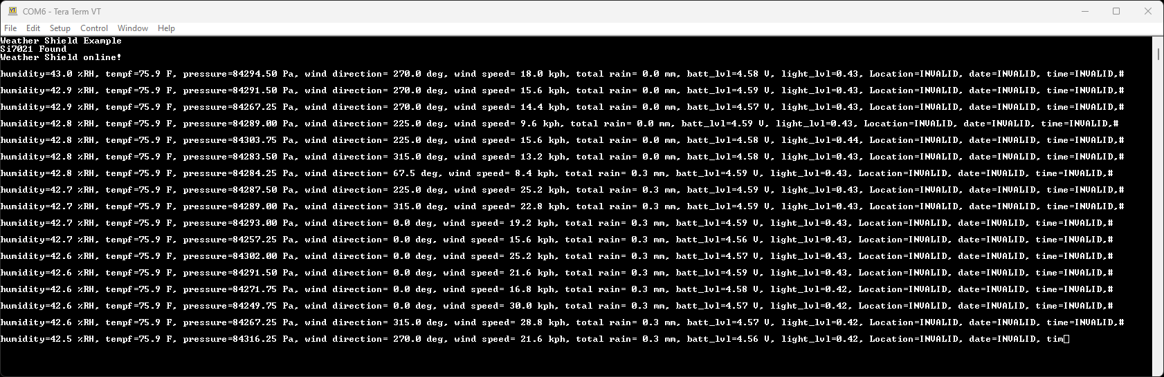
Note: The batt_lvl is indicating 4.08V. This is correct and is the actual voltage read from the Arduino powered over USB. The GPS module will add 50-80mA to the overall power consumption. If you are using a long or thin USB cable you may see significant voltage drop similar to this example. There is absolutely no harm in this! The Weather Shield runs at 3.3V and the Arduino will continue to run just fine down to about 3V. The reading is very helpful for monitoring your power source (USB, battery, solar, etc).
This example demonstrates how you can get location, altitude, and time from the GPS module. This would be helpful with weather stations that are moving such as balloon satellites, AVL, package tracking, and even static stations where you need to know precise altitude or timestamps.
Troubleshooting
Not working as expected and need help?
If you need technical assistance and more information on a product that is not working as you expected, we recommend heading on over to the SparkFun Technical Assistance page for some initial troubleshooting.
If you don't find what you need there, our SparkFun Forums are a great place to find and ask for help.
I2C Error
If there is an error you will see:
I2C communication to sensors is not working. Check solder connections.
This message appears when the board is unable to get a response from the I2C sensors. This could be because of a faulty solder connection, or if there are other devices on the A5/A4 lines (which are also called SDA/SCL).
Barometeric Reading
The Weather Shield example firmware outputs regular barometric pressure. This is very different from the pressure that weather stations report. For more information, see the definition of "altimeter setting pressure". For an example of how to calculate altimeter setting type barometric pressure see the MPL3115A2 hook-up guide. Also check out the MPL3115A2 library, specifically the BarometricHgInch example.
No GPS Data
Even if the GPS module doesn't have a fix, it should still transmit blank NMEA sentences. However, if there is no serial data being transmitted from the GPS module, the following error will be displayed before the GPS data.
No GPS data: check wiring/switch.
If the GPS module is connected properly, double check the switch position on the board and that the RX/TX pin connections are defined properly in the sketch.
Status LEDs
- In the example firmware, the blue LED should blink when the data from the weather sensors are being transmitted.
- In the example firmware, the green LED will only turn on when the GPS data has been updated. The LED may blink, as blank or incomplete NMEA sentences get parsed from the GPS module.
- There is a commented out block of code, if users wish to reconfigure the logic for the LED to check for new GPS data that is also valid.
Resources and Going Further
There's a lot of technology on this shield. Here's the datasheets in case you need to reference them:
- Schematic
- Eagle Files
- Datasheets
- Arduino Libraries
- Hardware GitHub Repository
Additional resources and projects to check out:
Consider adding an OpenLog for data logging the weather readings over time. For some wireless weather fun, check out our other weather tutorials.