SparkFun GPS Breakout - XA1110 (Qwiic) Hookup Guide
Introduction
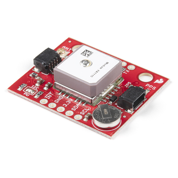
The XA1110 GPS module from GTOP is a rare bird indeed. GPS modules are hard to come by, but an I2C GPS+GLONASS module? Now we're cooking with peanut oil! This small module also utilizes the MediaTek MT3333 chipset, loaded with specialized SparkFun firmware that enables both I2C and Serial ports simultaneously. Using I2C means you won't have to tie up your serial port with GPS, leaving it open to other possibilities.
This module is configured with an on-board RTC battery that enables a warm-start functionality. (Giving the XA1110 just five seconds to first fix) A U.FL connector gives you the option to hook up an external antenna via a U.FL cable
This hookup guide will show you how to get started figuring out where on Earth you are. You'll also learn how to change the update rate of the GPS up to 10 Hz as well as change the baud rate.
Required Materials
To get started, you'll need a microcontroller to, well, control everything.
Particle Photon (Headers)
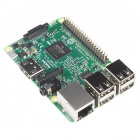
WRL-13774Raspberry Pi 3
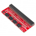
DEV-13825Now to get into the Qwiic ecosystem, the key will be one of the following Qwiic shields to match your preference of microcontroller:
SparkFun Qwiic Shield for Photon
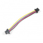
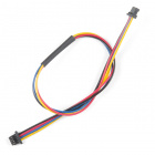
DEV-14477You will also need a Qwiic cable to connect the shield to your GPS module, choose a length that suits your needs.
Qwiic Cable - 100mm
PRT-14427Qwiic Cable - 50mm
PRT-14426Qwiic Cable - 200mm
PRT-14428Qwiic Cable - 500mm
PRT-14429Suggested Reading
If you aren't familiar with the Qwiic system, we recommend reading here for an overview.
 |
| Qwiic Connect System |
We would also recommend taking a look at the following tutorials if you aren't familiar with them.
GPS Basics
I2C
Qwiic Shield for Arduino & Photon Hookup Guide
Hardware Overview
Below is a table listing all of the hardware features and specs for the XA1110.
| Characteristic | Range |
|---|---|
| Operating Voltage | 3.3V: Regulated to 1.8V - 3.6V |
| Current | 25 mA (typical) |
| Hot/Warm/Cold Start | 1/5/15 seconds |
| Update Rate | 1 Hz (default), 0.1-10 Hz |
| I2C Interface | 100kHz & 400kHz (3.3V) |
| I2C Address | 0x10 |
| UART | 9600 bps (default), 4800-115200 bps (3.3V) |
| Position Accuracy | <3.0m, <2.5m with SBAS enabled |
| Satellites | 99 during search, 33 during tracking |
| Sensitivity | -148dBm Acquisition, -165dBm Tracking |
| Max Altitude | 80km (the mesosphere) using the example configuration sketch to enable high-altitude balloon mode |
| RTC Battery | 5.5mAh, enables warm start for 15 days without power |
Pins
The following table lists all of the XA1110's pins and their functionality.
| Pin | Description | Direction |
|---|---|---|
| GND | Ground | In |
| 3.3V | Power | In |
| SDA | Data | In |
| SCL | Clock | In |
| INT | Interrupt, goes low when NMEA data is ready, after packet is read, the pin pulls high | Out |
| Wake | Wake up | In |
| RST | Pulling low will reset the module | In |
| PPS | Provides one pulse-per-second signal | Out |
| RX | UART receiver; to receive commands | In |
| TX | UART transmitter; outputs GPS information | Out |
Optional Features
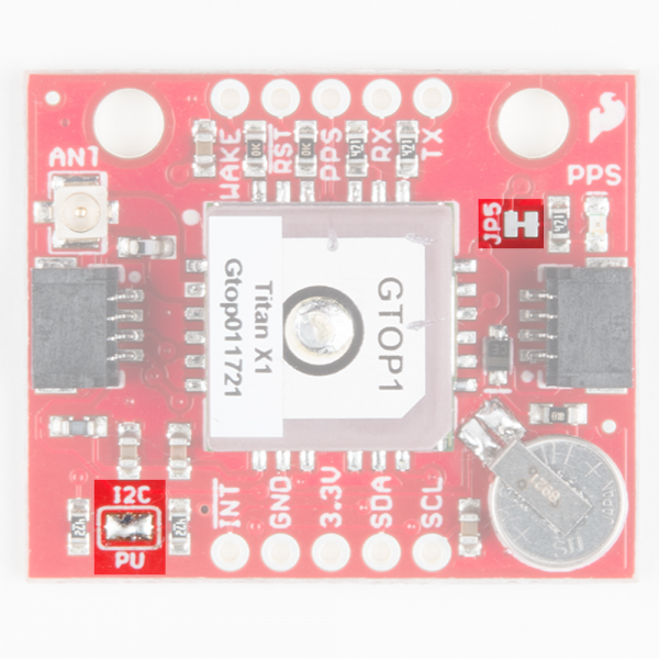
The XA1110 breakout has several optional features. The first of which is the option to disable the pulse-per-second LED. This can be done by slicing the connection on the JP5 jumper with a hobby knife. If multiple sensors are connected to the bus with the pull-up resistors enabled, the parallel equivalent resistance will create too strong of a pull-up for the bus to operate correctly. As a general rule of thumb, disable all but one pair of pull-up resistors if multiple devices are connected to the bus. If you need to disconnect the pull up resistors they can be removed by removing the solder on the pull up resistor jumper highlighted below. Both jumpers are shown in the below image.
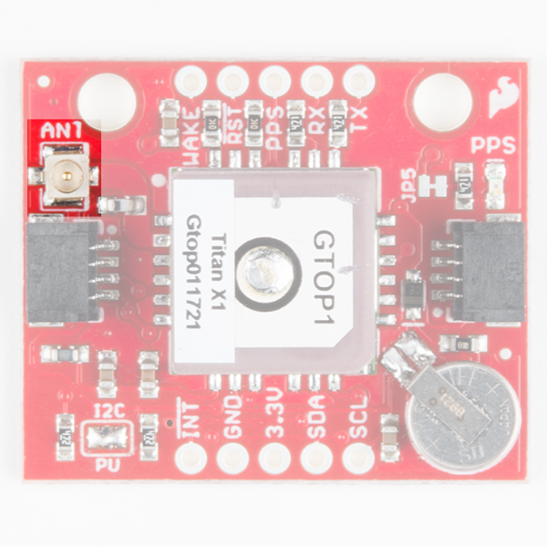
There is also a U.FL connector on the board, outlined below, which can be used in conjunction with the U.FL cable to connect to an external antenna
Hardware Assembly
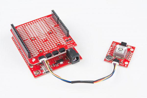
If you haven't yet assembled your Qwiic Shield, now would be the time to head on over to that tutorial. With the shield assembled, Sparkfun's new Qwiic environment means that connecting the sensor could not be easier. Just plug one end of the Qwiic cable into the XA1110 breakout, the other into the Qwiic Shield and you'll be ready to upload a sketch and figure out where you are. It seems too easy, but thats why we made it this way!
Library Overview
First, you'll need to download and install the Sparkfun I2C GPS library, this can be done using the button below or by using the Arduino Library Manager.
Note: This example assumes you are using the latest version of the Arduino IDE on your desktop. If this is your first time using Arduino, please review our tutorial on installing the Arduino IDE. If you have not previously installed an Arduino library, please check out our installation guide.
Before we get started developing a sketch, let's look at the available functions of the library.
boolean begin(TwoWire &wireport = Wire, uint32_t i2cSpeed = I2C_SPEED_STANDARD);---begin()is used to start the GPS, it runs sort of like this:- Starts running the I2C port at the given port and clock speed
- Pings the module and checks for a response
- Returns
TRUEif the response is received,FALSEif not.
void check();--- Checks the module for new data.uint8_t available();--- Returns the available number of bytes. Will call check() if zero is available.uint8_t read();--- Returns the next available byte.void enableDebugging(Stream &debugPort = Serial);--- Outputs various messages to assist in debugging.void disableDebugging();--- Pretty self explanatory, turns off debugging.boolean sendMTKpacket(String command);--- Can be used to send a command or configuration to the GPS module.- The input buffer on the MTK is 255 bytes, so strings must be shorter than 255 bytes.
- After ending a transmission, give the module 10 ms to process the message.
String createMTKpacket(uint16_t packetType, String dataField);--- Creates a config sentence (String) from a packetType and any settings. See 'MTK NMEA Packet' datasheet for more info.String calcCRCforMTK(String sentence);--- XORs bytes to create MTK packet.
Note: Due to a new QZSS satellite recently launched by the Japanese, users in the Asia-Pacific region (Longitude 70 to -160 degrees East) can experience huge drifts in location over the course of 2 hours. In order to remedy this, two options are available. The first is to simply reset the module every 2 hours. The second option is to disable the QZSS feature entirely. To do this, simply use the following command in your setup loop. sendMTKpacket($PMTK352,1*2B
Example Code
You should have downloaded the SparkFun I2C GPS Library in the previous step, if not, go back and click the button to download it. Within should be contained the library along with five examples. We're going to get you started with the first two examples.
Upload the following example to the microcontroller of your choice.
language:c
#include "SparkFun_I2C_GPS_Arduino_Library.h"
I2CGPS myI2CGPS; //Hook object to the library

void setup()
{
  Serial.begin(115200);
  Serial.println("GTOP Read Example");

  if (myI2CGPS.begin() == false)//Checks for succesful initialization of GPS
  {
    Serial.println("Module failed to respond. Please check wiring.");
    while (1); //Freeze!
  }
  Serial.println("GPS module found!");
}

void loop() //Writes GPS data to the Serial port with a baud rate of 115200
{
  while (myI2CGPS.available()) //available() returns the number of new bytes available from the GPS module
  {
    byte incoming = myI2CGPS.read(); //Read the latest byte from Qwiic GPS

    if(incoming == '$') Serial.println(); //Break the sentences onto new lines
    Serial.write(incoming); //Print this character
  }
}
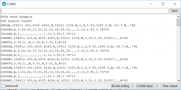
This first example outputs the raw NMEA sentences. Which look something like this:
If your GPS doesn't have a satellite fix, you will simply get zeroes instead of numbers. These NMEA sentences may be a little hard to wrap your head around if you don't fluently speak GPS, so let's move onto the second example, which will take this data, and use the TinyGPS library to transform it into some sensible latitude and longitude data. The second example requires the TinyGPS library, which can be downloaded using the button below.
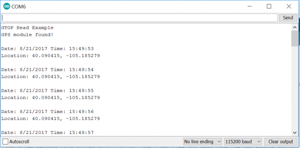
The below example code will take these NMEA sentences and use the displayInfo() function to output some nice and friendly latitude and longitude readings.
language:c
#include <SparkFun_I2C_GPS_Arduino_Library.h> //Use Library Manager or download here: https://github.com/sparkfun/SparkFun_I2C_GPS_Arduino_Library
I2CGPS myI2CGPS; //Hook object to the library

#include <TinyGPS++.h> //From: https://github.com/mikalhart/TinyGPSPlus
TinyGPSPlus gps; //Declare gps object

void setup()
{
  Serial.begin(115200);
  Serial.println("GTOP Read Example");

  if (myI2CGPS.begin() == false)
  {
    Serial.println("Module failed to respond. Please check wiring.");
    while (1); //Freeze!
  }
  Serial.println("GPS module found!");
}

void loop()
{
  while (myI2CGPS.available()) //available() returns the number of new bytes available from the GPS module
  {
    gps.encode(myI2CGPS.read()); //Feed the GPS parser
  }

  if (gps.time.isUpdated()) //Check to see if new GPS info is available
  {
    displayInfo();
  }
}

//Display new GPS info
void displayInfo()
{
  //We have new GPS data to deal with!
  Serial.println();

  if (gps.time.isValid())
  {
    Serial.print(F("Date: "));
    Serial.print(gps.date.month());
    Serial.print(F("/"));
    Serial.print(gps.date.day());
    Serial.print(F("/"));
    Serial.print(gps.date.year());

    Serial.print((" Time: "));
    if (gps.time.hour() < 10) Serial.print(F("0"));
    Serial.print(gps.time.hour());
    Serial.print(F(":"));
    if (gps.time.minute() < 10) Serial.print(F("0"));
    Serial.print(gps.time.minute());
    Serial.print(F(":"));
    if (gps.time.second() < 10) Serial.print(F("0"));
    Serial.print(gps.time.second());

    Serial.println(); //Done printing time
  }
  else
  {
    Serial.println(F("Time not yet valid"));
  }

  if (gps.location.isValid())
  {
    Serial.print("Location: ");
    Serial.print(gps.location.lat(), 6);
    Serial.print(F(", "));
    Serial.print(gps.location.lng(), 6);
    Serial.println();
  }
  else
  {
    Serial.println(F("Location not yet valid"));
  }
}
The output of this code in the serial monitor should look similar to the below image. If the module does not yet have a fix, you will see Location not yet valid instead of a latitude and longitude reading.
Resources and Going Further
You've finally figured out where you are! Now it's time to take this GPS and incorporate it into your own project.
For a little more information, check the resources below:
- Schematic (PDF)
- Eagle Files (ZIP)
- Example Sketches (ZIP)
- Arduino Library GitHub Repo
- Python Package GitHub Repo
- Qwiic System Landing Page
- GPS Module XA1110 Datasheet (PDF)
- NMEA over I2C Application Note (PDF)
- MediaTek Protocol and Packet Manual (PDF)
- The GitHub Repo will always have the latest design files.
For more GPS related fun, check out these other SparkFun tutorials.
