LSM9DS0 Hookup Guide
 jimblom
Introduction
The LSM9DS0 is a versatile, motion-sensing system-in-a-chip. It houses a 3-axis accelerometer, 3-axis gyroscope, and 3-axis magnetometer -- nine degrees of freedom (9DOF) in a single IC! Each sensor in the LSM9DS0 supports a wide range of...ranges: the accelerometer's scale can be set to ± 2, 4, 6, 8, or 16 g, the gyroscope supports ± 245, 500, and 2000 °/s, and the magnetometer has full-scale ranges of ± 2, 4, 8, or 12 gauss. The IMU-in-a-chip is so cool we put it on a breakout board.
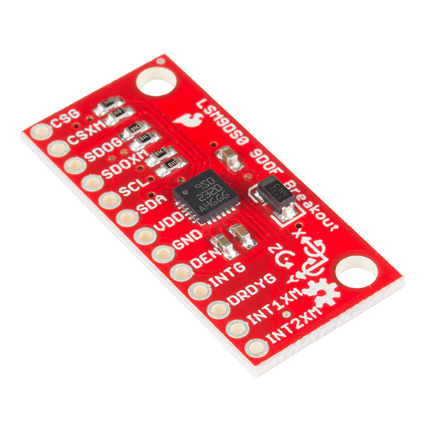
The LSM9DS0 is equipped with a digital interface, but even that is flexible: it supports both I2C and SPI, so you'll be hard-pressed to find a microcontroller it doesn't work with.
Covered In This Tutorial
This tutorial is devoted to all things LSM9DS0. We'll introduce you to the chip itself, then the breakout board. Then we'll switch over to example code, and show you how to interface with the board using an Arduino and our SFE_LSM9DS0 Arduino library.
The tutorial is split into the following pages:
- About the LSM9DS0 -- An overview of the LSM9DS0, examining its features and capabilities.
- Breakout Overview -- This page covers the LSM9DS0 Breakout Board -- topics like the pinout, jumpers, and schematic.
- Hardware Assembly -- Assembly tips and tricks, plus some information about the breakout's dimensions.
- Basic Arduino Example -- How to install the Arduino library, and use a simple example sketch.
- Advanced Arduino Example -- A more advanced Arduino sketch -- using the library -- showing off features like switch the sensors' scales and data rates.
- Using the Arduino Library -- An overview of the SFE_LSM9DS0 Arduino library.
Required Materials
This tutorial explains how to use the LSM9DS0 Breakout Board with an Arduino. To follow along, you'll need the following materials:
- LSM9DS0 Breakout Board
- Arduino UNO, RedBoard, or another Arduino-compatible board
- Straight Male Headers -- Or wire. Something to connect between the breakout and a breadboard.
- Breadboard -- Any size (even mini) should do.
- M/M Jumper Wires -- To connect between Arduino and breadboard.
- Logic Level Converter (any of the following could work)
- Bi-Directional Logic Level Converter -- MOSFET-based level shifter (this is what the tutorial uses).
- PCA9306 Bi-Directional Voltage Translator -- Solid I2C-focused level shifter.
A logic level shifter is required for any 5V-operating Arduino (UNO, RedBoard, Leonardo, etc). If you use a 3.3V-based 'duino -- like the Arduino Pro 3.3V or 3.3V Pro Mini -- there is no need for level shifting.
Suggested Reading
If you're not familiar with some of the concepts below, we recommend checking out that tutorial before continuing on.
About the LSM9DS0
The LSM9DS0 is one of only a handful of IC's that can measure three key properties of movement -- angular velocity, acceleration, and heading -- in a single IC.
The gyroscope can measure angular velocity -- that is "how fast, and along which axis, am I rotating?" Angular velocities are measured in degrees per second -- usually abbreviated to DPS or °/s. The LSM9DS0 can measure up to ± 2000 DPS, though that scale can also be set to either 245 or 500 DPS to get a finer resolution.
An accelerometer measures acceleration, which indicates how fast velocity is changing -- "how fast am I speeding up or slowing down?" Acceleration is usually either measured in m/s2 (meters per second per second) or g's (gravities [about 9.8 m/s2]). If an object is sitting motionless it feels about 1 g of acceleration towards the ground (assuming that ground is on earth, and the object is near sea-level). The LSM9DS0 measures its acceleration in g's, and its scale can be set to either ± 2, 4, 6, 8, or 16_g_.
Finally, there's the magnetometer, which measures the power and direction of magnetic fields. Though they're not easily visible, magnetic fields exist all around us -- whether you're holding a tiny ferromagnet or feeling an attraction to Earth's magnetic field. The LSM9DS0 measures magnetic fields in units of gauss (Gs), and can set its measurement scale to either ± 2, 4, 8, or 12 Gs.
By measuring these three properties, you can gain a great deal of knowledge about an object's movement. 9DOF's have tons and tons of applications. Measuring the force and direction of Earth's magnetic field with a magnetometer, you can approximate your heading. An accelerometer in your phone can measure the direction of the force of gravity, and estimate orientation (portrait, landscape, flat, etc.). Quadcopters with built-in gyroscopes can look out for sudden rolls or pitches, and correct their momentum before things get out of hand.

The LSM9DS0 measures each of these movement properties in three dimensions. That means it produces nine pieces of data: acceleration in x/y/z, angular rotation in x/y/z, and magnetic force in x/y/z. On the breakout board, the z-axis runs normal to the PCB, the y-axis runs parallel to the short edge, and the x-axis is parallel to the long edge. Each axis has a positive and negative direction as well, noted by the direction of the arrow on the label.
The LSM9DS0 is, in a sense, two IC's smashed into one package -- like if you combined an L3G4200D gyro with an LSM303DLMTR accel/mag. One half of the device takes care of all-things gyroscope, and the other half manages both the accelerometer and magnetometer. In fact, a few of the control pins are dedicated to a single sensor -- there are two chip select pins (CSG for the gyro and CSXM for the accel/mag) and two serial data out pins (SDOG and SDOXM).
Choose Your Own Adventure: SPI or I2C
In addition to being able to measure a wide variety of movement vectors, the LSM9DS0 is also multi-featured on the hardware end. It supports both SPI and I2C, so you should have no difficulty finding a microcontroller that can talk to it.
SPI is generally the easier of the two to implement, but it also requires more wires -- four versus I2C's two.
Because the LSM9DS0 supports both methods of communication, some pins have to pull double-duty. The Serial Data Out pin for example, does just that for SPI mode, but if you're using the device over I2C it becomes an address selector. Chip select activates SPI mode when it's low, but if it's pulled high the device assumes I2C communication. In the section below we discuss each of the LSM9DS0's pins, pay close attention to those pins that support both interfaces.
For much more detailed information about the IC, we encourage you to check out the datasheet!
Breakout Overview
Now that you know everything you need to about the LSM9DS0 IC, let's talk a bit about the breakout board it's resting on. On this page we'll discuss the pins that are broken out, and some of the other features on the board.
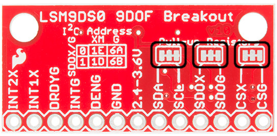
The Pinout
In total, the LSM9DS0 Breakout breaks out 13 pins.
Here's an overview of each of the pin functions:
| Pin Label | Pin Function | Notes |
|---|---|---|
| CSG | Chip Select Gyro | This pin selects between I2C and SPI on the gyro. Keep it HIGH for I2C, or use it as an (active-low) chip select for SPI. HIGH (1): SPI idle mode / I2C enabled LOW (0): SPI enabled / I2C disabled. |
| CSXM | Chip Select Accel/Mag (XM) | This pin selects between I2C and SPI on the XM. Keep it HIGH for I2C, or use it as an (active-low) chip select for SPI. HIGH (1): SPI idle mode / I2C enabled LOW (0): SPI enabled / I2C disabled. |
| SDOG | SPI: Gyroscope MISO I2C: Gyro address select | In SPI mode, this is the gyroscope data output (SDO_G). In I2C mode, this selects the LSb of the I2C address (SA0_G) |
| SDOXM | SPI: Accel/Mag MISO I2C: XM address select | In SPI mode, this is the XM data output (SDO_XM). In I2C mode, this selects the LSb of the I2C address (SA0_XM) |
| SCL | Serial Clock | I2C and SPI serial clock. |
| SDA | SPI: MOSI I2C:Serial Data | SPI: Device data in (MOSI) I2C: Serial data (bi-directional) |
| VDD | Power Supply | Supply voltage to the chip. Should be regulated between 2.4V and 3.6V. |
| GND | Ground | 0V voltage supply |
| DEN | Gyroscope Data Enable | Mostly unknown. The LSM9DS0 datasheet doesn't have much to say about this pin. |
| INTG | Gyro Programmable Interrupt | An interrupt that can be programmed as active high/low, push-pull, or open drain. It can trigger on over/under rotation speeds. |
| DRDYG | Gyroscope data ready | An interrupt that can indicate new gyro data is ready or buffer overrun. |
| INT1XM | Accel/Mag Interrupt 1 | A programmable interrupt that can trigger on data ready, over-acceleration or "taps". |
| INT2XM | Accel/Mag Interrupt 2 | A programmable interrupt that can trigger on data ready, over-acceleration or "taps". |
These pins can all be classified into one of three categories: communication, interrupts, or power.
Power Supply
The VDD and GND pins are where you'll supply a voltage and 0V reference to the IC. The breakout board does not regulate this voltage, so make sure it falls within the allowed supply voltage range of the LSM9DS0: 2.4V to 3.6V. Below is the electrical characteristics table from the datasheet.
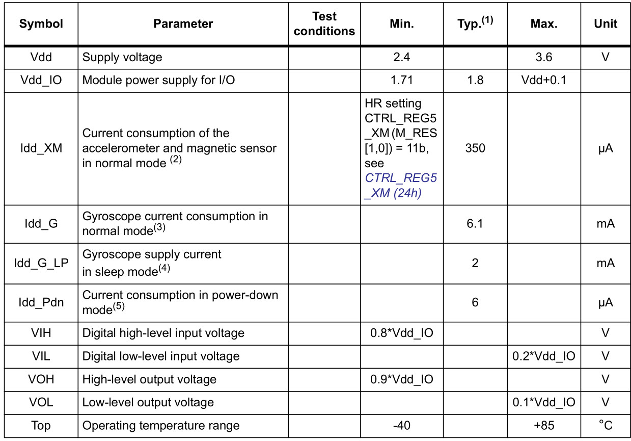
The communication pins are not 5V tolerant, so they'll need to be regulated to within a few mV of VDD.
Another very cool thing about this sensor is how low-power it is. In normal operation -- with every sensor turned on -- it'll pull around 6.5mA.
Communication
CSG, CSXM, SDOG, SDOXM, SCL, and SDA are all used for the I2C and SPI interfaces. The function of these pins depends upon which of the two interfaces you're using.
If you're using using I2C here's how you might configure these pins:
- Pull CSG and CSXM HIGH. This will set both the gyro and accel/mag to I2C mode.
- Set SDOG and SDOXM either HIGH or LOW. These pins set the I2C address of the gyro and accel/mag sensors.
- Connect SCL to your microcontroller's SCL pin.
- Connect SDA to your microcontroller's SDA pin.
- The board has a built-in 10kΩ pull-up resistor on both SDA and SCL lines. If that value is too high, you can add a second 10kΩ resistor in parallel to divide the pull-up resistance to about 5kΩ.
Or, if you're using SPI:
- Connect CSG and CSXM to two individually controllable pins on your microcontroller. These chip-selects are active-low -- when the pin goes LOW, SPI communication with either the gyro (CSG) or accel/mag (CSXM) is enabled.
- SDOG and SDOXM are the serial data out pins. In many cases you'll want to connect them together, and wire them to your microcontroller's MISO (master-in, slave-out) pin.
- Connect SCL to your microcontroller's SCLK (serial clock) pin.
- Connect SDA to your microcontroller's MOSI (master-out, slave-in) pin.
Interrupts
There are a variety of interrupts on the LSM9DS0. While connecting up to these is not as critical as the communication or power supply pins, using them will help you get the most out of the chip.
The accelerometer- and magnetometer-specific interrupts are INT1XM and INT2XM. These can both be programmed to interrupt as either active-high or active-low, triggering on events like data ready, tap-detection, or when an acceleration or magnetic field passes a set threshold.
DRDY and INTG are devoted gyroscope interrupts. DRDY can be programmed to go high or low when new gyroscope readings are ready to read. INTG is a little more customizable, it can be used to trigger whenever angular rotation exceeds a threshold on any axis.
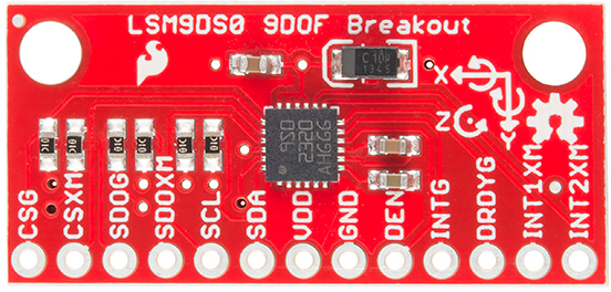
The Jumpers
Flipping the LSM9DS0 breakout over reveals three two-way, surface mount jumpers. Each of these jumpers comes closed. Their purpose is to automatically put the LSM9DS0 into I2C mode.
Each of these jumpers pulls a pair of pins up to VDD, through a 10kΩ resistor. The middle pad of the jumper connects to the resistor, and the edge pads connect to a pin (follow the labels to find out which one). You can see how those jumpers match up on the schematic:
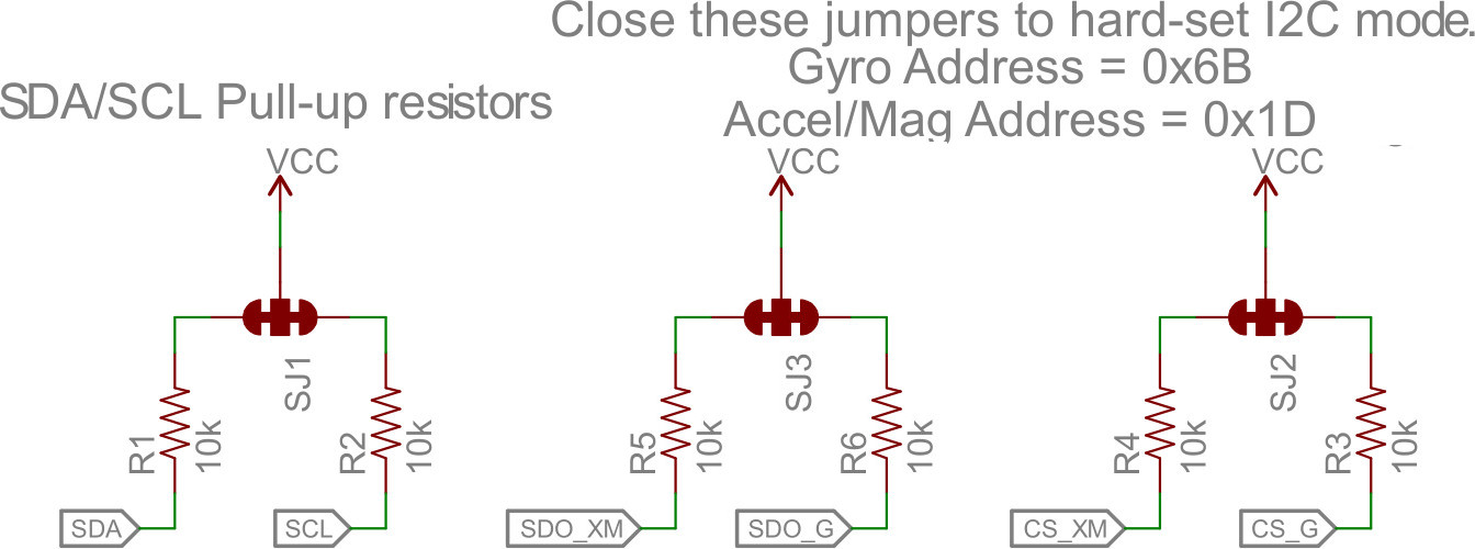
The far-right jumper connects CSG and CSXM to a pull-up -- this'll set the LSM9DS0 to I2C mode. The middle jumper pulls up SDOG and SDOXM, which sets the I2C address of the chip. Finally, the far-left jumper adds pull-up resistors to the I2C communication pins -- SDA and SCL.
The intention of these jumpers is to make it as easy-as-possible to use the board; using as few wires as possible. If you're using the breakout with I2C, you can ignore the four SDO and CS pins.
To disable any of these jumpers, whip out your handy hobby knife, and carefully cut the small traces between middle pad and edge pads. Even if you're using SPI, though, the jumpers shouldn't hinder your ability to communicate with the chip.
For more information about the breakout board, we encourage you to check out the schematic. Or, if you really want to delve into the anatomy of the PCB, you can download the EAGLE files.
Hardware Assembly
On this page we'll discuss assembly hints. There's really not much to assembling the breakout board -- the real key is soldering something into the breakout holes.
Solder Something
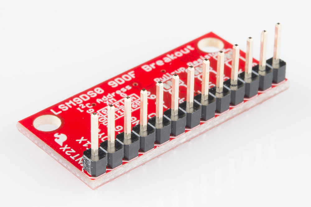
To get a solid electrical and physical connection to the LSM9DS0 Breakout, you'll need to solder either connectors or wires to the break-out pins. What, exactly, you solder into the board depends on how you're going to use it.
If you're going to use the breakout board in a breadboard or similar 0.1"-spaced perfboard, we recommend soldering straight male headers into the pins (there are also long headers if you need 'em).
If you're going to mount the breakout into a tight place, you may want to opt for soldering wires (stranded or solid-core) into the pins.
Mounting the Breakout
Because the LSM9DS0 senses motion, it's important (for most applications, at least) to keep in pinned in place. So the boards have a pair of mounting holes on the corners opposite the pins. The drill holes are 0.13" in diameter, so they should accommodate any 4/40 screw.
If you have any further dimension-related questions, hopefully the dimensional drawing below can answer them:
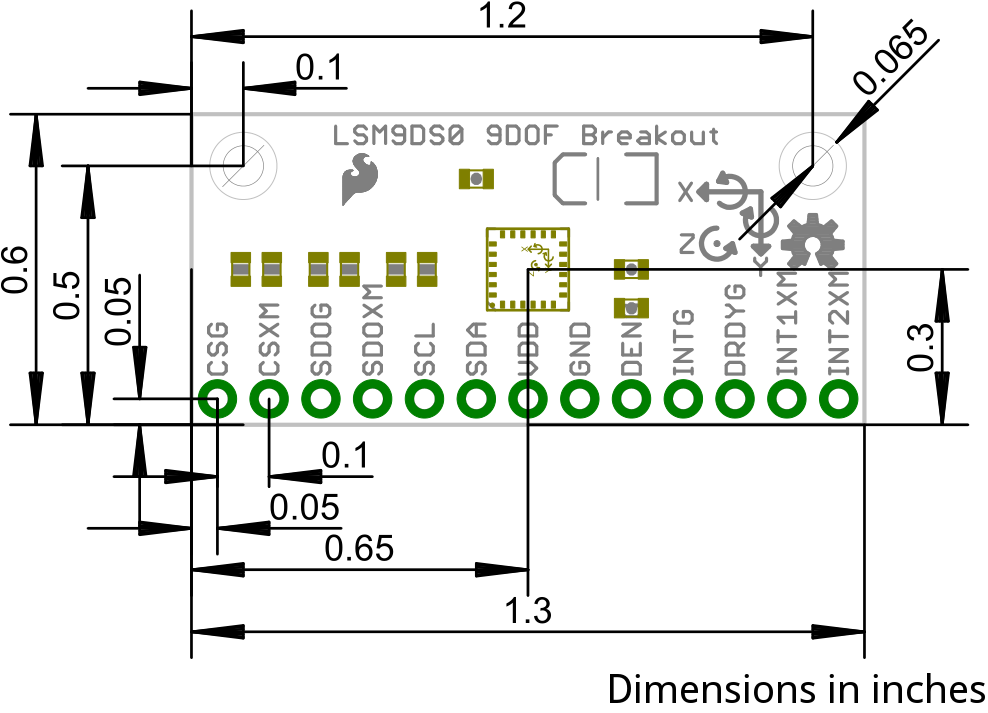
Consult the EAGLE PCB design files to find out more about the Breakout's dimensions.
Basic Arduino Example
This example will show you how to download and install the SFE_LSM9DS0 library, and use it in it's most basic form. We'll use I2C and ignore the interrupts, which means we'll be using as few wires and Arduino pins as possible.
Download and Install the Library
We've written a full-featured Arduino library to help make interfacing with the LSM9DS0's gyro and accelerometer/magnetometer as easy-as-possible. Visit the GitHub repository to download the most recent version of the library, or click the link below:
For help installing the library, check out our How To Install An Arduino Library tutorial. You'll need to move the SFE_LSM9DS0 folder into a libraries folder within your Arduino sketchbook.
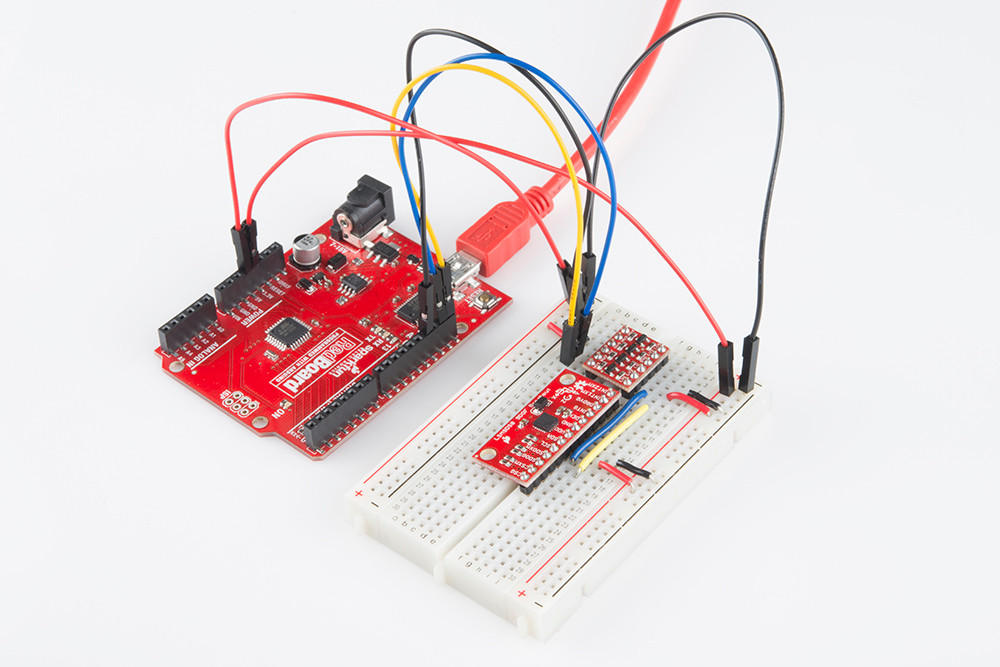
Simple Hardware Hookup (I2C)
The library will work with either I2C or SPI. Since we're trying to be as frugal with our Arduino pins as possible, I2C it is! Here's a fritzing diagram for this example:

This hookup relies on all of the jumpers on the back of the board being set (as they should be, unless they've been sliced). If the jumpers have been disconnected, connect all four CS and SDO pins to 3.3V.
Since we're using I2C all we have to do is connect SDA to SDA and SCL to SCL. Unfortunately, since the LSM9DS0's maximum operating voltage is 3.6V, we need to use a level shifting board to switch between 3.3V and 5V.
Alternatively, if you have a 3.3V-operating Arduino -- like the 3.3V/8MHz Pro -- you can connect SDA and SCL directly from microcontroller to sensor.
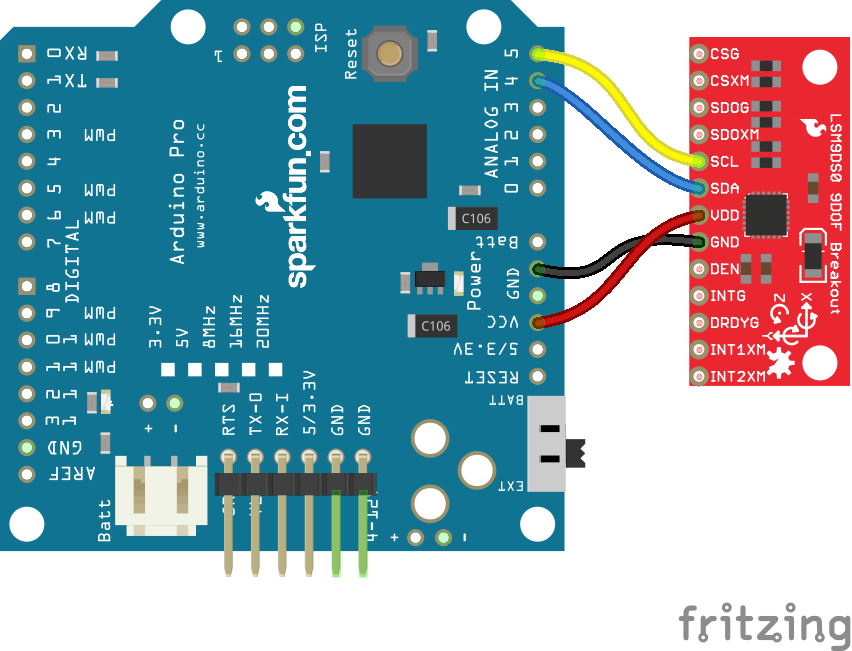
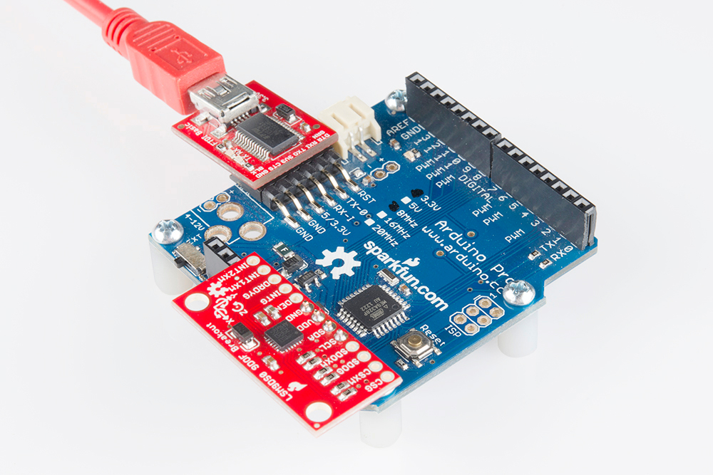
Heck, you can even mount the breakout board on top of the Arduino Pro. If you do this, you'll need to set A3 HIGH and A2 LOW. The sensor pulls little enough current that the Arduino's I/O pins can power it!
Open the LSM9DS0_Simple Example
Once you've installed the library, open Arduino (or restart it if it was already open). You'll find this first example under the File > Examples > SFE_LSM9DS0 > LSM9DS0_Simple:
language:c
/*****************************************************************
LSM9DS0_Simple.ino
SFE_LSM9DS0 Library Simple Example Code
Jim Lindblom @ SparkFun Electronics
Original Creation Date: February 18, 2014
https://github.com/sparkfun/LSM9DS0_Breakout

The LSM9DS0 is a versatile 9DOF sensor. It has a built-in
accelerometer, gyroscope, and magnetometer. Very cool! Plus it
functions over either SPI or I2C.

This Arduino sketch is a demo of the simple side of the
SFE_LSM9DS0 library. It'll demo the following:
* How to create a LSM9DS0 object, using a constructor (global
  variables section).
* How to use the begin() function of the LSM9DS0 class.
* How to read the gyroscope, accelerometer, and magnetometer
  using the readGryo(), readAccel(), readMag() functions and the
  gx, gy, gz, ax, ay, az, mx, my, and mz variables.
* How to calculate actual acceleration, rotation speed, magnetic
  field strength using the calcAccel(), calcGyro() and calcMag()
  functions.
* How to use the data from the LSM9DS0 to calculate orientation
  and heading.

Hardware setup: This library supports communicating with the
LSM9DS0 over either I2C or SPI. If you're using I2C, these are
the only connections that need to be made:
    LSM9DS0 --------- Arduino
     SCL ---------- SCL (A5 on older 'Duinos')
     SDA ---------- SDA (A4 on older 'Duinos')
     VDD ------------- 3.3V
     GND ------------- GND
(CSG, CSXM, SDOG, and SDOXM should all be pulled high jumpers on
  the breakout board will do this for you.)

If you're using SPI, here is an example hardware setup:
    LSM9DS0 --------- Arduino
          CSG -------------- 9
          CSXM ------------- 10
          SDOG ------------- 12
          SDOXM ------------ 12 (tied to SDOG)
          SCL -------------- 13
          SDA -------------- 11
          VDD -------------- 3.3V
          GND -------------- GND

The LSM9DS0 has a maximum voltage of 3.6V. Make sure you power it
off the 3.3V rail! And either use level shifters between SCL
and SDA or just use a 3.3V Arduino Pro.

Development environment specifics:
    IDE: Arduino 1.0.5
    Hardware Platform: Arduino Pro 3.3V/8MHz
    LSM9DS0 Breakout Version: 1.0

This code is beerware. If you see me (or any other SparkFun
employee) at the local, and you've found our code helpful, please
buy us a round!

Distributed as-is; no warranty is given.
*****************************************************************/

// The SFE_LSM9DS0 requires both the SPI and Wire libraries.
// Unfortunately, you'll need to include both in the Arduino
// sketch, before including the SFE_LSM9DS0 library.
#include <SPI.h> // Included for SFE_LSM9DS0 library
#include <Wire.h>
#include <SFE_LSM9DS0.h>

///////////////////////
// Example I2C Setup //
///////////////////////
// Comment out this section if you're using SPI
// SDO_XM and SDO_G are both grounded, so our addresses are:
#define LSM9DS0_XM  0x1D // Would be 0x1E if SDO_XM is LOW
#define LSM9DS0_G   0x6B // Would be 0x6A if SDO_G is LOW
// Create an instance of the LSM9DS0 library called `dof` the
// parameters for this constructor are:
// [SPI or I2C Mode declaration],[gyro I2C address],[xm I2C add.]
LSM9DS0 dof(MODE_I2C, LSM9DS0_G, LSM9DS0_XM);

///////////////////////
// Example SPI Setup //
///////////////////////
/* // Uncomment this section if you're using SPI
#define LSM9DS0_CSG  9  // CSG connected to Arduino pin 9
#define LSM9DS0_CSXM 10 // CSXM connected to Arduino pin 10
LSM9DS0 dof(MODE_SPI, LSM9DS0_CSG, LSM9DS0_CSXM);
*/

// Do you want to print calculated values or raw ADC ticks read
// from the sensor? Comment out ONE of the two #defines below
// to pick:
#define PRINT_CALCULATED
//#define PRINT_RAW

#define PRINT_SPEED 500 // 500 ms between prints

void setup()
{
  Serial.begin(115200); // Start serial at 115200 bps
  // Use the begin() function to initialize the LSM9DS0 library.
  // You can either call it with no parameters (the easy way):
  uint16_t status = dof.begin();
  // Or call it with declarations for sensor scales and data rates:
  //uint16_t status = dof.begin(dof.G_SCALE_2000DPS,
  //                            dof.A_SCALE_6G, dof.M_SCALE_2GS);

  // begin() returns a 16-bit value which includes both the gyro
  // and accelerometers WHO_AM_I response. You can check this to
  // make sure communication was successful.
  Serial.print("LSM9DS0 WHO_AM_I's returned: 0x");
  Serial.println(status, HEX);
  Serial.println("Should be 0x49D4");
  Serial.println();
}

void loop()
{
  printGyro();  // Print "G: gx, gy, gz"
  printAccel(); // Print "A: ax, ay, az"
  printMag();   // Print "M: mx, my, mz"

  // Print the heading and orientation for fun!
  printHeading((float) dof.mx, (float) dof.my);
  printOrientation(dof.calcAccel(dof.ax), dof.calcAccel(dof.ay),
                   dof.calcAccel(dof.az));
  Serial.println();

  delay(PRINT_SPEED);
}

void printGyro()
{
  // To read from the gyroscope, you must first call the
  // readGyro() function. When this exits, it'll update the
  // gx, gy, and gz variables with the most current data.
  dof.readGyro();

  // Now we can use the gx, gy, and gz variables as we please.
  // Either print them as raw ADC values, or calculated in DPS.
  Serial.print("G: ");
#ifdef PRINT_CALCULATED
  // If you want to print calculated values, you can use the
  // calcGyro helper function to convert a raw ADC value to
  // DPS. Give the function the value that you want to convert.
  Serial.print(dof.calcGyro(dof.gx), 2);
  Serial.print(", ");
  Serial.print(dof.calcGyro(dof.gy), 2);
  Serial.print(", ");
  Serial.println(dof.calcGyro(dof.gz), 2);
#elif defined PRINT_RAW
  Serial.print(dof.gx);
  Serial.print(", ");
  Serial.print(dof.gy);
  Serial.print(", ");
  Serial.println(dof.gz);
#endif
}

void printAccel()
{
  // To read from the accelerometer, you must first call the
  // readAccel() function. When this exits, it'll update the
  // ax, ay, and az variables with the most current data.
  dof.readAccel();

  // Now we can use the ax, ay, and az variables as we please.
  // Either print them as raw ADC values, or calculated in g's.
  Serial.print("A: ");
#ifdef PRINT_CALCULATED
  // If you want to print calculated values, you can use the
  // calcAccel helper function to convert a raw ADC value to
  // g's. Give the function the value that you want to convert.
  Serial.print(dof.calcAccel(dof.ax), 2);
  Serial.print(", ");
  Serial.print(dof.calcAccel(dof.ay), 2);
  Serial.print(", ");
  Serial.println(dof.calcAccel(dof.az), 2);
#elif defined PRINT_RAW
  Serial.print(dof.ax);
  Serial.print(", ");
  Serial.print(dof.ay);
  Serial.print(", ");
  Serial.println(dof.az);
#endif

}

void printMag()
{
  // To read from the magnetometer, you must first call the
  // readMag() function. When this exits, it'll update the
  // mx, my, and mz variables with the most current data.
  dof.readMag();

  // Now we can use the mx, my, and mz variables as we please.
  // Either print them as raw ADC values, or calculated in Gauss.
  Serial.print("M: ");
#ifdef PRINT_CALCULATED
  // If you want to print calculated values, you can use the
  // calcMag helper function to convert a raw ADC value to
  // Gauss. Give the function the value that you want to convert.
  Serial.print(dof.calcMag(dof.mx), 2);
  Serial.print(", ");
  Serial.print(dof.calcMag(dof.my), 2);
  Serial.print(", ");
  Serial.println(dof.calcMag(dof.mz), 2);
#elif defined PRINT_RAW
  Serial.print(dof.mx);
  Serial.print(", ");
  Serial.print(dof.my);
  Serial.print(", ");
  Serial.println(dof.mz);
#endif
}

// Here's a fun function to calculate your heading, using Earth's
// magnetic field.
// It only works if the sensor is flat (z-axis normal to Earth).
// Additionally, you may need to add or subtract a declination
// angle to get the heading normalized to your location.
// See: http://www.ngdc.noaa.gov/geomag/declination.shtml
void printHeading(float hx, float hy)
{
  float heading;

  if (hy > 0)
  {
    heading = 90 - (atan(hx / hy) * (180 / PI));
  }
  else if (hy < 0)
  {
    heading = - (atan(hx / hy) * (180 / PI));
  }
  else // hy = 0
  {
    if (hx < 0) heading = 180;
    else heading = 0;
  }

  Serial.print("Heading: ");
  Serial.println(heading, 2);
}

// Another fun function that does calculations based on the
// acclerometer data. This function will print your LSM9DS0's
// orientation -- it's roll and pitch angles.
void printOrientation(float x, float y, float z)
{
  float pitch, roll;

  pitch = atan2(x, sqrt(y * y) + (z * z));
  roll = atan2(y, sqrt(x * x) + (z * z));
  pitch *= 180.0 / PI;
  roll *= 180.0 / PI;

  Serial.print("Pitch, Roll: ");
  Serial.print(pitch, 2);
  Serial.print(", ");
  Serial.println(roll, 2);
}
After uploading the code, open up your serial monitor and set the baud rate to 115200 bps. You should see something like this begin to stream by:
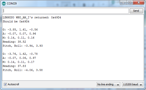
Each serial output blurb spits out the readings from all nine dimensions of movement. First the gyroscope readings ("G: x, y, z") in degrees per second (DPS). Then come three degrees of acceleration in g's ("A: x, y, z"), followed by the magnetic field readings ("M: x, y, z") in gauss (Gs).
Try moving your breadboard around (carefully, don't disconnect any wires!). Are the numbers changing? Check out the acceleration values -- the axis normal to gravity should feel about 1 g of acceleration on it.
Does the heading output what you'd expect? If north seems a few degrees off, you may need to adjust for your declination. That means adding or subtracting a constant number that correlates to your location on this map.
That's all there is to it! If you want to get more out of the LSM9DS0 by using the interrupt outputs, check out the next page! Or check out the Using the Arduino Library Page for help using the library.
Advanced Arduino Example
The basic example is perfect if all you want to do is poll the LSM9DS0 a few times per second to get movement data, but what if you want to make use of the IMU's interrupt outputs? Using interrupts you can get read data in from the LSM9DS0 as soon as it's available. This example will show you how to get more out of your LSM9DS0 Breakout.
Circuit Diagram
In addition to the SDA and SCL pins, this example will make use of the DRDYG, INT1XM, and INT2XM pins. Here's the hookup diagram:
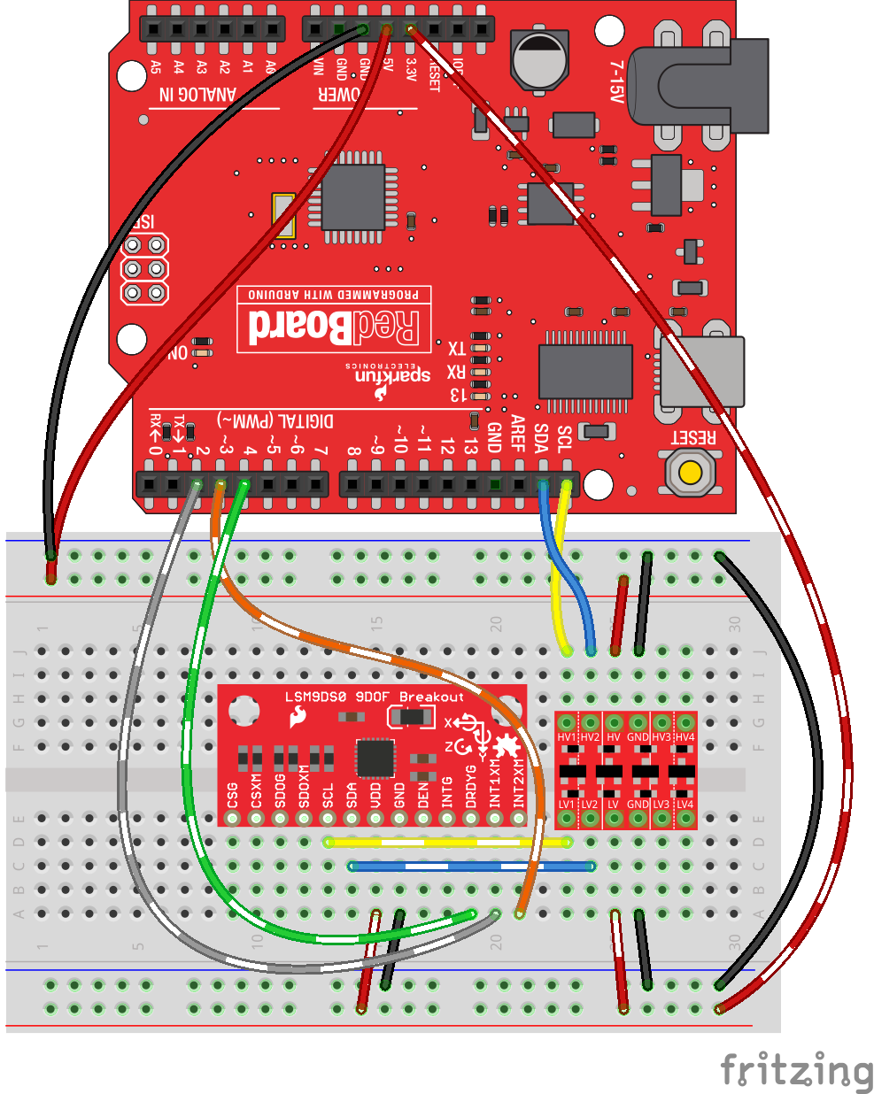
Again, you'll need to use a logic level converter between SDAs and SCLs. There is no need for level shifting on the three interrupt lines -- the 3.3V output from the LSM9DS0 will be enough to trigger a logic high on the Arduino (see Logic Levels).
Example Code: LSM9DS0_SerialMenus
Open up the LSM9DS0_SerialMenus example by going to File > Examples > SFE_LSM9DS0 > LSM9DS0_SerialMenus. Here's the code:
language:c
/*****************************************************************
LSM9DS0_SerialMenus.ino
SFE_LSM9DS0 Library Example Code: Interact With Serial Menus
Jim Lindblom @ SparkFun Electronics
Original Creation Date: February 14, 2014 (Happy Valentines Day!)
https://github.com/sparkfun/LSM9DS0_Breakout

This Arduino sketch is a demo of all things SEF_LSM9DS0 library.
Once you attach all hardware, and upload the sketch, open your
Serial monitor at 115200 BPS. Follow the menu prompts to either:
    1) Stream readings from the accelerometer.
    2) Stream readings from the gyroscope.
    3) Stream readings from the magnetometer.
    4) Set the scales of each sensor (e.g. +/-4g, 500DPS, 8Gs)
    5) Switch to/from calculated or raw data (e.g. ADC ticks or
        g's, DPS, and Gs)
    6) Set the output data rate of each sensor.

Hardware setup: This library supports communicating with the
LSM9DS0 over either I2C or SPI. In addition to those wires, this
sketch demos how to use the interrupts. Here's what the I2C setup
looks like:
    LSM9DS0 --------- Arduino
     CSG ------------- NONE (Pulled HIGH [indicates I2C mode])
     CSXM ------------ NONE (Pulled HIGH [indicates I2C mode])
     SDOG ------------ NONE (Pulled HIGH [sets I2C address])
     SDOXM ----------- NONE (Pulled HIGH [sets I2C address])
     SCL ---------- SCL (A5 on older 'Duinos')
     SDA ---------- SDA (A4 on older 'Duinos')
     VDD ------------- 3.3V
     GND ------------- GND
     DEN ------------- NONE (Not used in this example)
     INTG ------------ NONE (Not used in this example)
     DRDYG ------------ 4 (Could be any digital pin)
     INT1XM ----------- 3 (Could be any digital pin)
     INT2XM ----------- 2 (Could be any digital pin)

The LSM9DS0 has a maximum voltage of 3.6V. Make sure you power it
off the 3.3V rail! And either use level shifters between SCL
and SDA or just use a 3.3V Arduino Pro.

Development environment specifics:
    IDE: Arduino 1.0.5
    Hardware Platform: Arduino Pro 3.3V/8MHz
    LSM9DS0 Breakout Version: 1.0

This code is beerware; if you see me (or any other SparkFun
employee) at the local, and you've found our code helpful, please
buy us a round!

Distributed as-is; no warranty is given.
*****************************************************************/

// The SFE_LSM9DS0 requires both the SPI and Wire libraries.
// Unfortunately, you'll need to include both in the Arduino
// sketch, before including the SFE_LSM9DS0 library.
#include <SPI.h> // Included for SFE_LSM9DS0 library
#include <Wire.h>
#include <SFE_LSM9DS0.h>

///////////////////////
// Example I2C Setup //
///////////////////////
// SDO_XM and SDO_G are both grounded, therefore our addresses are:
#define LSM9DS0_XM  0x1D // Would be 0x1E if SDO_XM is LOW
#define LSM9DS0_G   0x6B // Would be 0x6A if SDO_G is LOW
// Create an instance of the LSM9DS0 library called `dof` the
// parameters for this constructor are:
// [SPI or I2C Mode declaration], [gyro I2C address], [xm I2C address]
LSM9DS0 dof(MODE_I2C, LSM9DS0_G, LSM9DS0_XM);

///////////////////////
// Example SPI Setup //
///////////////////////
//#define LSM9DS0_CSG  9  // CSG connected to Arduino pin 9
//#define LSM9DS0_CSXM 10 // CSXM connected to Arduino pin 10
//LSM9DS0 dof(MODE_SPI, LSM9DS0_CSG, LSM9DS0_CSXM);

///////////////////////////////
// Interrupt Pin Definitions //
///////////////////////////////
const byte INT1XM = 2; // INT1XM tells us when accel data is ready
const byte INT2XM = 3; // INT2XM tells us when mag data is ready
const byte DRDYG = 4;  // DRDYG tells us when gyro data is ready

// A boolean to keep track of whether we're printing raw (ADC)
// or calculated (g's, DPS, Gs) sensor data:
boolean printRaw = true;

void setup()
{
  // Set up interrupt pins as inputs:
  pinMode(INT1XM, INPUT);
  pinMode(INT2XM, INPUT);
  pinMode(DRDYG, INPUT);

  Serial.begin(115200); // Start serial at 115200 bps
  // Use the begin() function to initialize the LSM9DS0 library.
  // You can either call it with no parameters (the easy way):
  uint16_t status = dof.begin();
  // Or call it with declarations for sensor scales and data rates:
  //uint16_t status = dof.begin(dof.G_SCALE_2000DPS, dof.A_SCALE_6G, dof.M_SCALE_2GS);

  // begin() returns a 16-bit value which includes both the gyro and
  // accelerometers WHO_AM_I response. You can check this to make sure
  // communication was successful.
  Serial.println(status, HEX);
}

void loop()
{
  // Print the control menu:
  printMenu();
  // Then wait for any serial data to come in:
  while (!Serial.available())
    ;
  // Once serial data is received, call parseMenu to act on it:
  parseMenu(Serial.read());

}

void printAccel()
{
  // Only read from the accelerometer if the accel interrupts,
  // which means that new data is ready.
  if (digitalRead(INT1XM))
  {
    // Use the readAccel() function to get new data from the accel.
    // After calling this function, new values will be stored in
    // the ax, ay, and az variables.
    dof.readAccel();

    Serial.print("A: ");
    if (printRaw)
    {
      Serial.print(dof.ax);
      Serial.print(", ");
      Serial.print(dof.ay);
      Serial.print(", ");
      Serial.println(dof.az);
    }
    else
    {
      Serial.print(dof.calcAccel(dof.ax));
      Serial.print(", ");
      Serial.print(dof.calcAccel(dof.ay));
      Serial.print(", ");
      Serial.println(dof.calcAccel(dof.az));
    }
  }
}

void printGyro()
{
  // Only read from the gyro if the DRDY interrupts,
  // which means that new data is ready.
  if (digitalRead(DRDYG))
  {
    // Use the readGyro() function to get new data from the gyro.
    // After calling this function, new values will be stored in
    // the gx, gy, and gz variables.
    dof.readGyro();

    Serial.print("G: ");
    if (printRaw)
    {
      Serial.print(dof.gx);
      Serial.print(", ");
      Serial.print(dof.gy);
      Serial.print(", ");
      Serial.println(dof.gz);
    }
    else
    {
      Serial.print(dof.calcGyro(dof.gx));
      Serial.print(", ");
      Serial.print(dof.calcGyro(dof.gy));
      Serial.print(", ");
      Serial.println(dof.calcGyro(dof.gz));
    }
  }
}

void printMag()
{
  // Only read from the magnetometer if the INT2XM interrupts,
  // which means that new data is ready.
  if (digitalRead(INT2XM))
  {
    // Use the readMag() function to get new data from the mag.
    // After calling this function, new values will be stored in
    // the mx, my, and mz variables.
    dof.readMag();

    Serial.print("M: ");
    if (printRaw)
    {
      Serial.print(dof.mx);
      Serial.print(", ");
      Serial.print(dof.my);
      Serial.print(", ");
      Serial.print(dof.mz);
      Serial.print(", ");
      Serial.println(calcHeading(dof.mx, dof.my, dof.mz));
    }
    else
    {
      Serial.print(dof.calcMag(dof.mx), 4);
      Serial.print(", ");
      Serial.print(dof.calcMag(dof.my), 4);
      Serial.print(", ");
      Serial.print(dof.calcMag(dof.mz), 4);
      Serial.print(", ");
      Serial.println(calcHeading(dof.mx, dof.my, dof.mz));
    }
  }
}

// Here's a simple example function to calculate heading based on
// magnetometer readings. This only works when the 9DOF is flat
// (x-axis normal to gravity).
float calcHeading(float hx, float hy, float hz)
{
  if (hy > 0)
  {
    return 90 - atan(hx / hy) * 180 / PI;
  }
  else if (hy < 0)
  {
    return 270 - atan(hx / hy) * 180 / PI;
  }
  else // hy = 0
  {
    if (hx < 0) return 180;
    else return 0;
  }
}

// This function will print all data from all sensors at once.
// It'll wait until every sensor interrupt triggers before
// printing.
void streamAll()
{
  if ((digitalRead(INT2XM)) && (digitalRead(INT1XM)) &&
      (digitalRead(DRDYG)))
  {
    printAccel();
    printGyro();
    printMag();
  }
}

void setScale()
{
  char c;

  Serial.println(F("Set accelerometer scale:"));
  Serial.println(F("\t1) +/- 2G"));
  Serial.println(F("\t2) +/- 4G"));
  Serial.println(F("\t3) +/- 6G"));
  Serial.println(F("\t4) +/- 8G"));
  Serial.println(F("\t5) +/- 16G"));
  while (Serial.available() < 1)
    ;
  c = Serial.read();
  switch (c)
  {
    case '1':
      dof.setAccelScale(dof.A_SCALE_2G);
      break;
    case '2':
      dof.setAccelScale(dof.A_SCALE_4G);
      break;
    case '3':
      dof.setAccelScale(dof.A_SCALE_6G);
      break;
    case '4':
      dof.setAccelScale(dof.A_SCALE_8G);
      break;
    case '5':
      dof.setAccelScale(dof.A_SCALE_16G);
      break;
  }

  Serial.println(F("Set gyroscope scale:"));
  Serial.println(F("\t1) +/- 245 DPS"));
  Serial.println(F("\t2) +/- 500 DPS"));
  Serial.println(F("\t3) +/- 2000 DPS"));
  while (Serial.available() < 1)
    ;
  c = Serial.read();
  switch (c)
  {
    case '1':
      dof.setGyroScale(dof.G_SCALE_245DPS);
      break;
    case '2':
      dof.setGyroScale(dof.G_SCALE_500DPS);
      break;
    case '3':
      dof.setGyroScale(dof.G_SCALE_2000DPS);
      break;
  }

  Serial.println(F("Set magnetometer scale:"));
  Serial.println(F("\t1) +/- 2GS"));
  Serial.println(F("\t2) +/- 4GS"));
  Serial.println(F("\t3) +/- 8GS"));
  Serial.println(F("\t4) +/- 12GS"));
  while (Serial.available() < 1)
    ;
  c = Serial.read();
  switch (c)
  {
    case '1':
      dof.setMagScale(dof.M_SCALE_2GS);
      break;
    case '2':
      dof.setMagScale(dof.M_SCALE_4GS);
      break;
    case '3':
      dof.setMagScale(dof.M_SCALE_8GS);
      break;
    case '4':
      dof.setMagScale(dof.M_SCALE_12GS);
      break;
  }
}

void setRaw()
{
  if (printRaw)
  {
    printRaw = false;
    Serial.println(F("Printing calculated readings"));
  }
  else
  {
    printRaw = true;
    Serial.println(F("Printing raw readings"));
  }
}

void setODR()
{
  char c;

  Serial.println(F("Set Accelerometer ODR (Hz):"));
  Serial.println(F("\t1) 3.125 \t 6) 100"));
  Serial.println(F("\t2) 6.25  \t 7) 200"));
  Serial.println(F("\t3) 12.5  \t 8) 400"));
  Serial.println(F("\t4) 25    \t 9) 800"));
  Serial.println(F("\t5) 50    \t A) 1600"));
  while (Serial.available() < 1)
    ;
  c = Serial.read();
  switch (c)
  {
    case '1':
      dof.setAccelODR(dof.A_ODR_3125);
      break;
    case '2':
      dof.setAccelODR(dof.A_ODR_625);
      break;
    case '3':
      dof.setAccelODR(dof.A_ODR_125);
      break;
    case '4':
      dof.setAccelODR(dof.A_ODR_25);
      break;
    case '5':
      dof.setAccelODR(dof.A_ODR_50);
      break;
    case '6':
      dof.setAccelODR(dof.A_ODR_100);
      break;
    case '7':
      dof.setAccelODR(dof.A_ODR_200);
      break;
    case '8':
      dof.setAccelODR(dof.A_ODR_400);
      break;
    case '9':
      dof.setAccelODR(dof.A_ODR_800);
      break;
    case 'A':
    case 'a':
      dof.setAccelODR(dof.A_ODR_1600);
      break;
  }

  Serial.println(F("Set Gyro ODR/Cutoff (Hz):"));
  Serial.println(F("\t1) 95/12.5 \t 8) 380/25"));
  Serial.println(F("\t2) 95/25   \t 9) 380/50"));
  Serial.println(F("\t3) 190/125 \t A) 380/100"));
  Serial.println(F("\t4) 190/25  \t B) 760/30"));
  Serial.println(F("\t5) 190/50  \t C) 760/35"));
  Serial.println(F("\t6) 190/70  \t D) 760/50"));
  Serial.println(F("\t7) 380/20  \t E) 760/100"));
  while (Serial.available() < 1)
    ;
  c = Serial.read();
  switch (c)
  {
    case '1':
      dof.setGyroODR(dof.G_ODR_95_BW_125);
      break;
    case '2':
      dof.setGyroODR(dof.G_ODR_95_BW_25);
      break;
    case '3':
      dof.setGyroODR(dof.G_ODR_190_BW_125);
      break;
    case '4':
      dof.setGyroODR(dof.G_ODR_190_BW_25);
      break;
    case '5':
      dof.setGyroODR(dof.G_ODR_190_BW_50);
      break;
    case '6':
      dof.setGyroODR(dof.G_ODR_190_BW_70);
      break;
    case '7':
      dof.setGyroODR(dof.G_ODR_380_BW_20);
      break;
    case '8':
      dof.setGyroODR(dof.G_ODR_380_BW_25);
      break;
    case '9':
      dof.setGyroODR(dof.G_ODR_380_BW_50);
      break;
    case 'A':
    case 'a':
      dof.setGyroODR(dof.G_ODR_380_BW_100);
      break;
    case 'B':
    case 'b':
      dof.setGyroODR(dof.G_ODR_760_BW_30);
      break;
    case 'C':
    case 'c':
      dof.setGyroODR(dof.G_ODR_760_BW_35);
      break;
    case 'D':
    case 'd':
      dof.setGyroODR(dof.G_ODR_760_BW_50);
      break;
    case 'E':
    case 'e':
      dof.setGyroODR(dof.G_ODR_760_BW_100);
      break;
  }

  Serial.println(F("Set Magnetometer ODR (Hz):"));
  Serial.println(F("\t1) 3.125 \t 4) 25"));
  Serial.println(F("\t2) 6.25  \t 5) 50"));
  Serial.println(F("\t3) 12.5  \t 6) 100"));
  while (Serial.available() < 1)
    ;
  c = Serial.read();
  switch (c)
  {
    case '1':
      dof.setMagODR(dof.M_ODR_3125);
      break;
    case '2':
      dof.setMagODR(dof.M_ODR_625);
      break;
    case '3':
      dof.setMagODR(dof.M_ODR_125);
      break;
    case '4':
      dof.setMagODR(dof.M_ODR_25);
      break;
    case '5':
      dof.setMagODR(dof.M_ODR_50);
      break;
    case '6':
      dof.setMagODR(dof.M_ODR_100);
      break;
  }
}

void printMenu()
{
  Serial.println();
  Serial.println(F("////////////////////////////////////////////"));
  Serial.println(F("// LSM9DS0 Super Awesome Amazing Fun Time //"));
  Serial.println(F("////////////////////////////////////////////"));
  Serial.println();
  Serial.println(F("1) Stream Accelerometer"));
  Serial.println(F("2) Stream Gyroscope"));
  Serial.println(F("3) Stream Magnetometer"));
  Serial.println(F("4) Stream output from all sensors"));
  Serial.println(F("5) Set Sensor Scales"));
  Serial.println(F("6) Switch To/From Raw/Calculated Readings"));
  Serial.println(F("7) Set Output Data Rates"));
  Serial.println();
}

void parseMenu(char c)
{
  switch (c)
  {
    case '1':
      while(!Serial.available())
        printAccel();
      break;
    case '2':
      while(!Serial.available())
        printGyro();
      break;
    case '3':
      while(!Serial.available())
        printMag();
      break;
    case '4':
      while(!Serial.available())
      {
        streamAll();
      }
      break;
    case '5':
      setScale();
      break;
    case '6':
      setRaw();
      break;
    case '7':
      setODR();
      break;
  }
}
Upload the code, then open up your serial monitor with the baud rate set to 115200 bps. Then just follow the menu prompts to interact with the sensor. You can stream the accelerometer, gyroscope, and magnetometer individually or together.
Send any key to stop the streaming and bring the menu back.
There are also menu items that allow you to set the range and data rates of the sensors. Make sure you give those a spin, and see how they affect the output of the sensor.
Using the Arduino Library
Those two basic and advanced tutorials show off everything that the SFE_LSM9DS0 library can do. If you're stumped on how to use the library, though, here are some of its key concepts and functions:
Setup Stuff
To enable the library, you'll need to include it, and you also need to include the SPI and Wire libraries:
language:c
#include <SPI.h> // Included for SFE_LSM9DS0 library
#include <Wire.h>
#include <SFE_LSM9DS0.h>
Make sure the SPI and Wire includes are above the SFE_LSM9DS0.
Constructor
The constructor creates an instance of the LSM9DS0 class. Once you've created the instance, that's what you'll use to control the breakout from there on. This single line of code is usually placed in the global area of your sketch.
The constructor tells the library three things: whether you're using I2C or SPI, and the addresses of the gyroscope and accelerometer/magnetomter sensors. If you're using I2C, those address are the 7-bit address defined in the datasheet
language:c
// SDO_XM and SDO_G are both grounded, so our addresses are:
#define LSM9DS0_XM  0x1D // Would be 0x1E if SDO_XM is LOW
#define LSM9DS0_G   0x6B // Would be 0x6A if SDO_G is LOW
// Create an instance of the LSM9DS0 library called `dof` the
// parameters for this constructor are:
// [SPI or I2C Mode declaration],[gyro I2C address],[xm I2C add.]
LSM9DS0 dof(MODE_I2C, LSM9DS0_G, LSM9DS0_XM);
If you're using SPI, the gyro and accel/mag addresses should be the Arduino pin connected to each chip-select pin (CSG and CSXM).
language:c
#define LSM9DS0_CSG  9  // CSG connected to Arduino pin 9
#define LSM9DS0_CSXM 10 // CSXM connected to Arduino pin 10
LSM9DS0 dof(MODE_SPI, LSM9DS0_CSG, LSM9DS0_CSXM);
Your LSM9DS0 class object can be named like any other variable. In our examples we called it dof -- short and sweet.
begin()
Once you've created an LSM9DS0 object, you can start using it! The first step is initializing the sensor, by using the begin() function. You can either call this function with no parameters, to get a good, default init:
language:c
// Initialize LSM9DS0, setting gyro scale to 245 DPS, accel to 2g, and mag to 2Gs.
// Also set data rates to 95 Hz (gyro), 50 Hz (accel), and 50 Hz (mag).
dof.begin();
Or, give it a whole set of parameters that set each sensors scale and data rate.
language:c
// Initialize LSM9DS0, setting gyro scale to 500 DPS, accel to +/-16g, and mag to 12Gs.
// Also set data rates to 760 Hz (gyro), 1600 Hz (accel), and 100 Hz (mag) (lots of data!)
dof.begin(G_SCALE_500DPS, A_SCALE_16G, M_SCALE_12GS, G_ODR_760_BW_100, A_ODR_1600, M_ODR_100);
There are a variety of options for the scale and data rate selections. Consult SFE_LSM9DS0.h to find out more.
Reading and Interpreting the Sensors
What good is the sensor if you can't get any data from it!? Here are the functions you'll need to get acceleration, rotation speed, and magnetic field strength dat from the library.
readAccel(), readGyro(), and readMag()
These three functions -- readAccel(), readGyro(), and readMag() -- poll the LSM9DS0 to get the most up-to-date readings from each of the three sensors.
The read functions don't take any parameters, and they don't return anything, so how do you get that data? After the function runs its course, it'll update a set of three class variables, which will have the sensor data you so desire. readAccel() will update ax, ay, and az, readGyro() will update gx, gy, and gz, and readMag() will update mx, my, and mz. Here's an example:
language:c
dof.readAccel(); // Update the accelerometer data
Serial.print(dof.ax); // Print x-axis data
Serial.print(", ");
Serial.print(dof.ay); // print y-axis data
Serial.print(", ");
Serial.println(dof.az); // print z-axis data
Those values are all signed 16-bit integers, meaning they'll range from -32,768 to 32,767. That value doesn't mean much unless you know the scale of your sensor, which is where the next functions come into play.
calcAccel(), calcGyro(), and calcMag()
The library keeps track of each sensor's scale, and it implements these helper functions to make translating between the raw ADC readings of the sensor to actual units easy.
calcAccel(), calcGyro(), and calcMag() all take a single parameter -- a signed 16-bit integer -- and convert to their respective units. They all return a float value, which you can do with as you please.
Here's an example of printing calculated gyroscope values:
language:c
dof.readGyro(); // Update gyroscope data
Serial.print(dof.calcGyro(dof.gx)); // Print x-axis rotation in DPS
Serial.print(", ");
Serial.print(dof.calcGyro(dof.gy)); // Print y-axis rotation in DPS
Serial.print(", ");
Serial.println(dof.calcGyro(dof.gz)); // Print z-axis rotation in DPS
The library also implements functions to individually set a sensor's scale or data rate. For more help using the library, check out comments in the example code, or delve into the library code itself.
Resources and Going Further
Hopefully that info dump was enough to get you rolling with the LSM9DS0. If you need any more information, here are some more resources:
- Schematic (PDF)
- EAGLE Files (ZIP)
- LSM9DS0 Datasheet (PDF) -- This datasheet covers everything from the hardware and pinout of the IC, to the register mapping of the gyroscope and accelerometer/magnetometer.
- Arduino Library
- GitHub Repo
- SFE Product Showcase
Now that you've got the LSM9DS0 up-and-running, what project are you going to incorporate motion-sensing into? Need a little inspiration? Check out some of these tutorials!
- Getting Started With the RedBot -- The RedBot is a great entry-level robotics platform. It'd be really neat to see what could be done with an LSM9DS0 connected to it.
- Dungeons and Dragons Dice Gauntlet -- This project uses an accelerometer to sense a "rolling the dice" motion. You could swap in the LSM9DS0 to add more functionality -- like compass-based damage multipliers!
- Leap Motion Teardown -- An IMU sensor is cool, but image-based motion sensing is the future. Check out this teardown of the miniature-Kinect-like Leap Motion!