LSM9DS0 Hookup Guide
 jimblom
Breakout Overview
Now that you know everything you need to about the LSM9DS0 IC, let's talk a bit about the breakout board it's resting on. On this page we'll discuss the pins that are broken out, and some of the other features on the board.
The Pinout
In total, the LSM9DS0 Breakout breaks out 13 pins.
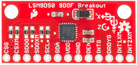
Here's an overview of each of the pin functions:
| Pin Label | Pin Function | Notes |
|---|---|---|
| CSG | Chip Select Gyro | This pin selects between I2C and SPI on the gyro. Keep it HIGH for I2C, or use it as an (active-low) chip select for SPI. HIGH (1): SPI idle mode / I2C enabled LOW (0): SPI enabled / I2C disabled. |
| CSXM | Chip Select Accel/Mag (XM) | This pin selects between I2C and SPI on the XM. Keep it HIGH for I2C, or use it as an (active-low) chip select for SPI. HIGH (1): SPI idle mode / I2C enabled LOW (0): SPI enabled / I2C disabled. |
| SDOG | SPI: Gyroscope MISO I2C: Gyro address select | In SPI mode, this is the gyroscope data output (SDO_G). In I2C mode, this selects the LSb of the I2C address (SA0_G) |
| SDOXM | SPI: Accel/Mag MISO I2C: XM address select | In SPI mode, this is the XM data output (SDO_XM). In I2C mode, this selects the LSb of the I2C address (SA0_XM) |
| SCL | Serial Clock | I2C and SPI serial clock. |
| SDA | SPI: MOSI I2C:Serial Data | SPI: Device data in (MOSI) I2C: Serial data (bi-directional) |
| VDD | Power Supply | Supply voltage to the chip. Should be regulated between 2.4V and 3.6V. |
| GND | Ground | 0V voltage supply |
| DEN | Gyroscope Data Enable | Mostly unknown. The LSM9DS0 datasheet doesn't have much to say about this pin. |
| INTG | Gyro Programmable Interrupt | An interrupt that can be programmed as active high/low, push-pull, or open drain. It can trigger on over/under rotation speeds. |
| DRDYG | Gyroscope data ready | An interrupt that can indicate new gyro data is ready or buffer overrun. |
| INT1XM | Accel/Mag Interrupt 1 | A programmable interrupt that can trigger on data ready, over-acceleration or "taps". |
| INT2XM | Accel/Mag Interrupt 2 | A programmable interrupt that can trigger on data ready, over-acceleration or "taps". |
These pins can all be classified into one of three categories: communication, interrupts, or power.
Power Supply
The VDD and GND pins are where you'll supply a voltage and 0V reference to the IC. The breakout board does not regulate this voltage, so make sure it falls within the allowed supply voltage range of the LSM9DS0: 2.4V to 3.6V. Below is the electrical characteristics table from the datasheet.
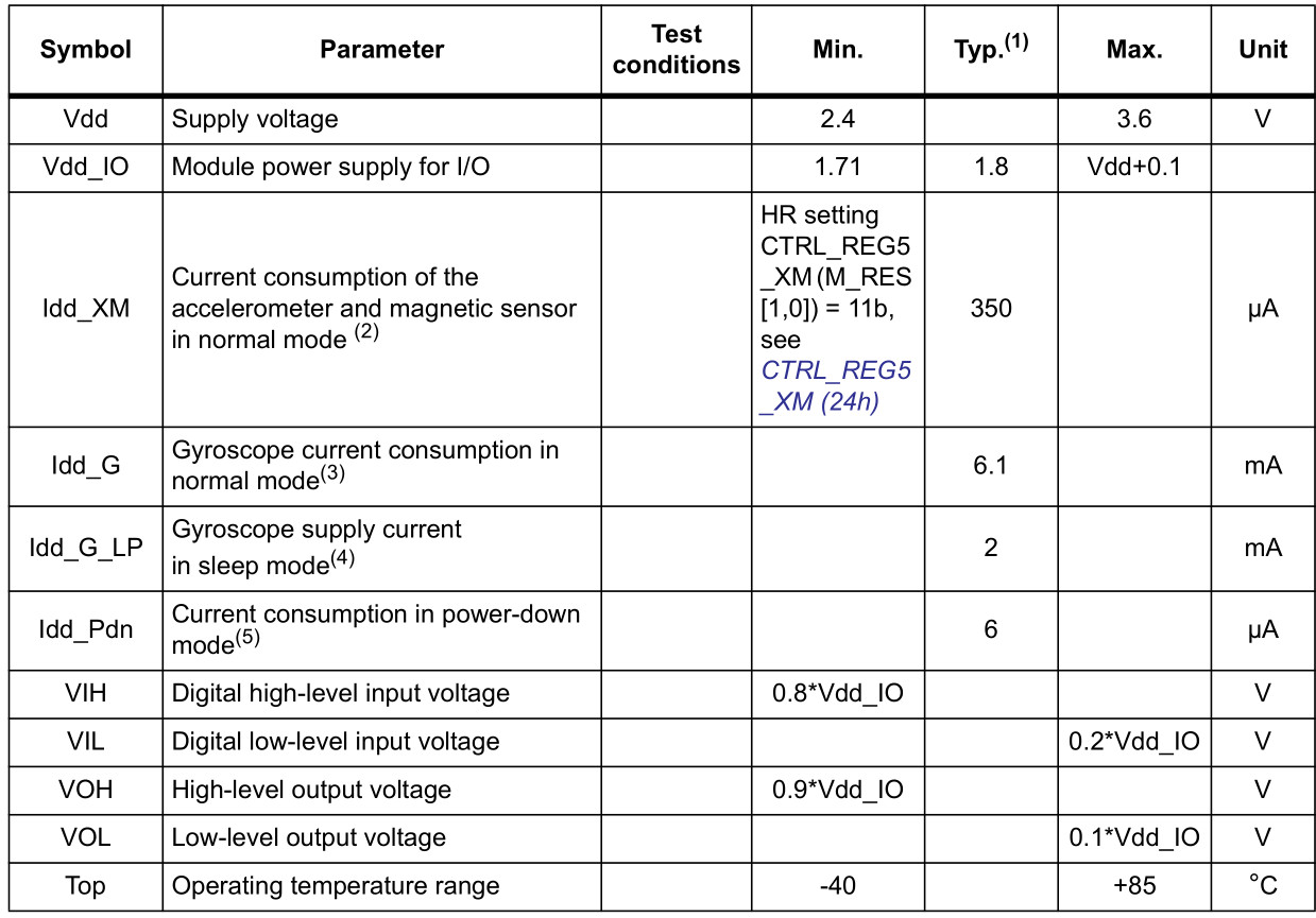
The communication pins are not 5V tolerant, so they'll need to be regulated to within a few mV of VDD.
Another very cool thing about this sensor is how low-power it is. In normal operation -- with every sensor turned on -- it'll pull around 6.5mA.
Communication
CSG, CSXM, SDOG, SDOXM, SCL, and SDA are all used for the I2C and SPI interfaces. The function of these pins depends upon which of the two interfaces you're using.
If you're using using I2C here's how you might configure these pins:
- Pull CSG and CSXM HIGH. This will set both the gyro and accel/mag to I2C mode.
- Set SDOG and SDOXM either HIGH or LOW. These pins set the I2C address of the gyro and accel/mag sensors.
- Connect SCL to your microcontroller's SCL pin.
- Connect SDA to your microcontroller's SDA pin.
- The board has a built-in 10kΩ pull-up resistor on both SDA and SCL lines. If that value is too high, you can add a second 10kΩ resistor in parallel to divide the pull-up resistance to about 5kΩ.
Or, if you're using SPI:
- Connect CSG and CSXM to two individually controllable pins on your microcontroller. These chip-selects are active-low -- when the pin goes LOW, SPI communication with either the gyro (CSG) or accel/mag (CSXM) is enabled.
- SDOG and SDOXM are the serial data out pins. In many cases you'll want to connect them together, and wire them to your microcontroller's MISO (master-in, slave-out) pin.
- Connect SCL to your microcontroller's SCLK (serial clock) pin.
- Connect SDA to your microcontroller's MOSI (master-out, slave-in) pin.
Interrupts
There are a variety of interrupts on the LSM9DS0. While connecting up to these is not as critical as the communication or power supply pins, using them will help you get the most out of the chip.
The accelerometer- and magnetometer-specific interrupts are INT1XM and INT2XM. These can both be programmed to interrupt as either active-high or active-low, triggering on events like data ready, tap-detection, or when an acceleration or magnetic field passes a set threshold.
DRDY and INTG are devoted gyroscope interrupts. DRDY can be programmed to go high or low when new gyroscope readings are ready to read. INTG is a little more customizable, it can be used to trigger whenever angular rotation exceeds a threshold on any axis.
The Jumpers
Flipping the LSM9DS0 breakout over reveals three two-way, surface mount jumpers. Each of these jumpers comes closed. Their purpose is to automatically put the LSM9DS0 into I2C mode.
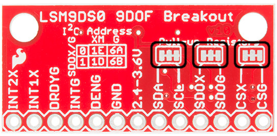
Each of these jumpers pulls a pair of pins up to VDD, through a 10kΩ resistor. The middle pad of the jumper connects to the resistor, and the edge pads connect to a pin (follow the labels to find out which one). You can see how those jumpers match up on the schematic:
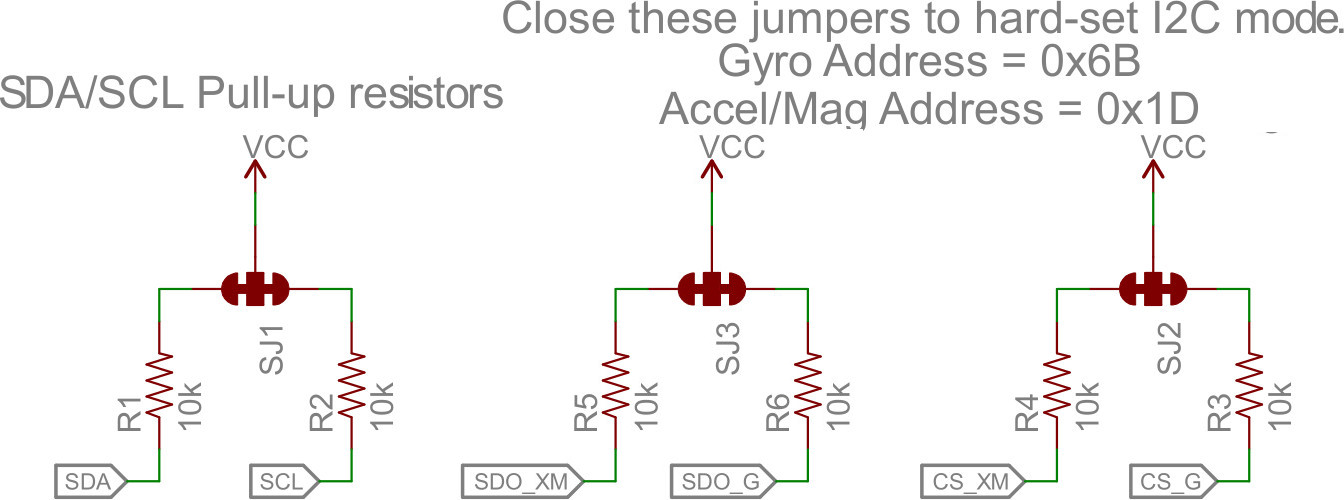
The far-right jumper connects CSG and CSXM to a pull-up -- this'll set the LSM9DS0 to I2C mode. The middle jumper pulls up SDOG and SDOXM, which sets the I2C address of the chip. Finally, the far-left jumper adds pull-up resistors to the I2C communication pins -- SDA and SCL.
The intention of these jumpers is to make it as easy-as-possible to use the board; using as few wires as possible. If you're using the breakout with I2C, you can ignore the four SDO and CS pins.
To disable any of these jumpers, whip out your handy hobby knife, and carefully cut the small traces between middle pad and edge pads. Even if you're using SPI, though, the jumpers shouldn't hinder your ability to communicate with the chip.
For more information about the breakout board, we encourage you to check out the schematic. Or, if you really want to delve into the anatomy of the PCB, you can download the EAGLE files.