LSM9DS0 Hookup Guide
 jimblom
Hardware Assembly
On this page we'll discuss assembly hints. There's really not much to assembling the breakout board -- the real key is soldering something into the breakout holes.
Solder Something
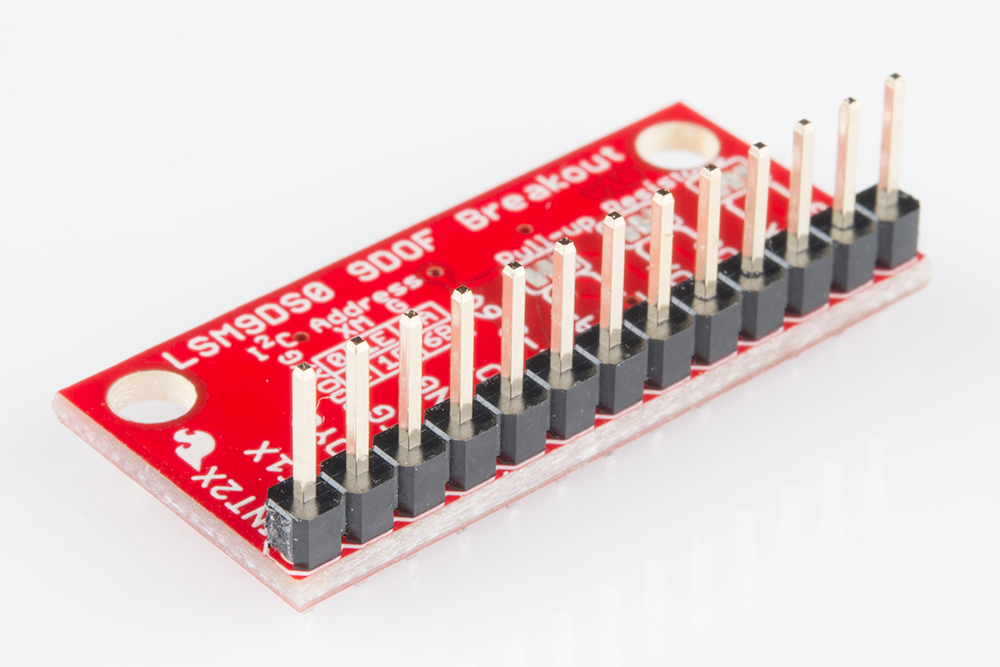
To get a solid electrical and physical connection to the LSM9DS0 Breakout, you'll need to solder either connectors or wires to the break-out pins. What, exactly, you solder into the board depends on how you're going to use it.
If you're going to use the breakout board in a breadboard or similar 0.1"-spaced perfboard, we recommend soldering straight male headers into the pins (there are also long headers if you need 'em).
If you're going to mount the breakout into a tight place, you may want to opt for soldering wires (stranded or solid-core) into the pins.
Mounting the Breakout
Because the LSM9DS0 senses motion, it's important (for most applications, at least) to keep in pinned in place. So the boards have a pair of mounting holes on the corners opposite the pins. The drill holes are 0.13" in diameter, so they should accommodate any 4/40 screw.
If you have any further dimension-related questions, hopefully the dimensional drawing below can answer them:
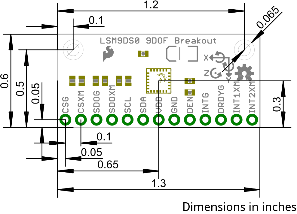
Consult the EAGLE PCB design files to find out more about the Breakout's dimensions.