Getting Started with the RedBot
This Tutorial is Retired!
This tutorial covers concepts or technologies that are no longer current. It's still here for you to read and enjoy, but may not be as useful as our newest tutorials.
 SFUptownMaker
Introduction
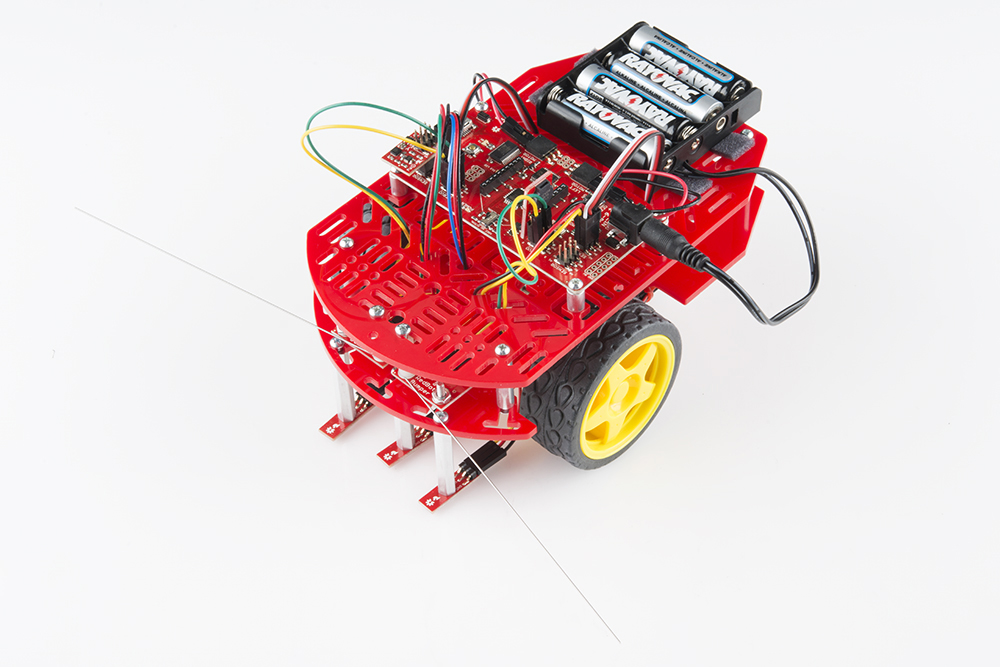
The RedBot is robotic development platform capable of teaching basic robotics and sensor integration! Based on the SparkFun RedBoard and programmable in the Arduino environment, the RedBot has all the I/O you need to make a small robot in no time at all. The RedBot family consists of the RedBot Mainboard (motor driver and main controller), sensor modules and add-ons, and The RedBot Kit.
We've also written a comprehensive Arduino library supporting the existing peripherals, which will be expanded to support additional peripherals as we add them. Once you've installed the library, you can program the RedBot using the "Arduino Uno" board option--no board definition files needed.
Suggested Reading
If you still need to assemble your RedBot, visit our RedBot Assembly Guide for detailed instructions.
Please Note: The RedBot Assembly Guide also includes instructions on how to hook up Dagu’s Wheel Encoder (not included in the RedBot Kit).
We also have a RedBot Experimental guide that will help you get your RedBot moving and doing cool things!
Before you go any further, you should probably make certain that you're familiar with these other topics:
- What is an Arduino? - Since the RedBot is based off the Arduino platform, it's a good idea to understand what that means.
- Installing the Arduino IDE - If you don't have the Arduino software installed, this guide will help you out.
- Installing an Arduino Library - To get the most out of the RedBot, you'll want to install our RedBot library. This tutorial will show you how.
- Accelerometer basics - One of the core sensors for the RedBot is an accelerometer. To find out more about accelerometers, check out this guide.
- Analog to digital conversion - Many useful sensors for the RedBot will be analog. This guide will help you interface with them and make the most of the data you get back.
- Pulse width modulation (PWM) - The RedBot includes two headers with PWM signals, and uses PWM to control the speed of the motors. It's probably a good idea to be familiar with the concept.
- I2C - The RedBot Accelerometer, which ships with the RedBot kit, uses I2C to communicate with the RedBot. While the accelerometer is accessible through the library with no knowledge of I2C required, if you want to get more out of it, you can check out this tutorial.
- Exploring XBees and XCTU - If you want to add remote controllability to the RedBot, XBees are the way to go. This tutorial will help show you how to set them up.
Hardware
RedBot Mainboard
The RedBot Mainboard was designed to be as versatile as possible. It has banks of 3-pin I/O break-outs for easily connecting up LEDs, Sensors, or motors. It also has an integrated [H-Bridge Driver]( (https://cdn.sparkfun.com/assets/learn_tutorials/1/1/0/TB6612FNG.pdf) chip. While we have developed an integrated library for the RedBot, if you want to drive the motors manually - here are the pin outs for the Motor Driver:
LEFT MOTOR:
- Control 1 - Pin 2
- Control 2 - Pin 4
- Motor PWM (Speed) - Pin 5
RIGHT MOTOR:
- Control 1 - Pin 7
- Control 2 - Pin 8
- Motor PWM (Speed) - Pin 6
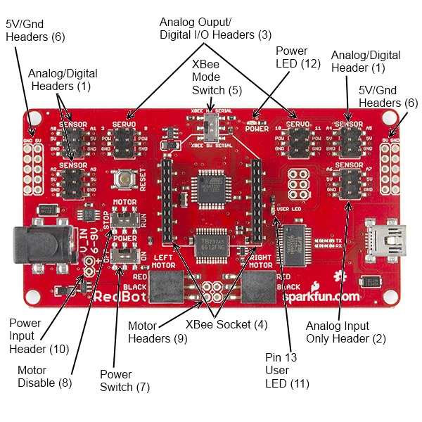
Here's a quick tour of the hardware that's on the board:
Analog/digital headers - These three headers provide one I/O pin, which can be used for analog input as well as digital input or output, as well as 5V power and ground. In addition, the header with A4 and A5 can be used for connecting I2C devices; the RedBot Accelerometer is designed to solder directly to this header, making connecting an accelerometer a snap.
Analog input header - This header provides an additional two analog input pins. These pins can't be used for digital signals, however.
Analog output/digital header - These two headers provide four pins which can be used for either PWM output or regular digital I/O. Note that the power supply for these headers is connected directly to the battery, providing extra umph for servo motors, but devices expecting 5V should not be connected directly to them!
Wireless Socket - The RedBot has a socket for an XBee module, providing easy wireless interfacing.
XBee Mode Switch A switch allows you to select whether the XBee communicates via the standard serial I/O pins (0 and 1, accessible through the built in Serial command set) or via pins 14 and 15 (A0 and A1), using the SoftwareSerial library. Using the software mode will consume two of your analog inputs, however.
5V / GND Headers - Headers are available to allow the user to tap off the 5V and ground signals.
Power Switch - A power switch puts the board into a very low power consumption mode (microamps or less) allowing you to turn the board off without pulling the power connection.
Motor Disable Switch - A motor disable switch allows you to turn off the motor driver so you can program the board without having it drive all over.
Motor Headers - Headers are available to easily connect up the right and left side motors. The motor control is powered by the TB6612FNG Motor Driver.
Power Input Header - A header has also been provided to allow you to access the input supply, either for purposes of driving additional circuitry or to allow more flexibility than the standard barrel jack does for power sources.
DEBUG LED (pin 13) - An LED is connected to pin 13 to allow basic sanity checks that code is loading and running on the board.
Power LED - A power LED will remain lit whenever the power switch is active.
Here's a quick Example program to test your RedBot out with. It spins the left motor forward and reverse, and the spins both motors forward and reverse.
Push the small reset button to restart the program.
language:c
/*******************************************************************************
/ SimpleRedBotDrive Code - no libraries
/
/ Simple example code showing how to spin the right and left motors and braking.
/ This example requires no libraries to run, and has all of the pins used on the
/ RedBot Mainboard defined.
/
/ Before uploading this code to your RedBot, make sure that the RedBot is in a safe
/ place. It will start moving immediately after you upload the program. We suggest
/ placing the RedBot on it's end so that the wheels are up.
/
/ Push the small reset button on the board to run the program again.
/
/ Note: The RedBot Mainboard programs as an Arduino Uno
/******************************************************************************/

// H-Bridge motor driver pins
#define    L_CTRL1   2
#define    L_CTRL2   4
#define    L_PWM     5

#define    R_CTRL1   7
#define    R_CTRL2   8
#define    R_PWM     6

// XBee SW_Serial pins
#define    SW_SER_TX A0
#define    SW_SER_RX A1


/*******************
/ setup function
/*******************/
void setup()
{
    Serial.begin(9600);

    pinMode(L_CTRL1, OUTPUT);  // used as a debug pin for an LED.
    pinMode(L_CTRL2, OUTPUT);  // used as a debug pin for an LED.
    pinMode(L_PWM, OUTPUT);  // used as a debug pin for an LED.

    pinMode(R_CTRL1, OUTPUT);  // used as a debug pin for an LED.
    pinMode(R_CTRL2, OUTPUT);  // used as a debug pin for an LED.
    pinMode(R_PWM, OUTPUT);  // used as a debug pin for an LED.

    pinMode(13, OUTPUT);  // used as a debug pin for an LED.


    // spin the left Motor CW
    leftMotor(255);
    delay(2000);
    leftBrake();
    delay(1000);  // wait for 1000 milliseconds


    // spin the left Motor CCW
    leftMotor(-255);
    delay(2000);
    leftBrake();
    delay(1000);  // wait for 1000 milliseconds

    // spin both motors (drive forward) -- left CW, right CCW
    leftMotor(255);
    rightMotor(-255);
    delay(2000);  // wait for 2000 milliseconds
    leftBrake();
    rightBrake();

    // spin both motors (drive in reverse) -- left CCW, right CW
    leftMotor(-255);
    rightMotor(255);
    delay(2000);  // wait for 2000 milliseconds
    leftBrake();
    rightBrake();

}

/*******************
/ loop function
/*******************/
void loop()
{
    // no code here. All driving code is in the setup() -- so that it runs just once.
}

/*******************************************************************************/
void leftMotor(int motorPower)
{
    motorPower = constrain(motorPower, -255, 255);   // constrain motorPower to -255 to +255
    if(motorPower >= 0)
    {
        // spin CW
        digitalWrite(L_CTRL1, HIGH);
        digitalWrite(L_CTRL2, LOW);
        analogWrite(L_PWM, abs(motorPower));
    }
    else
    {
        // spin CCW
        digitalWrite(L_CTRL1, LOW);
        digitalWrite(L_CTRL2, HIGH);
        analogWrite(L_PWM, abs(motorPower));
    }
}

/*******************************************************************************/
void leftBrake()
{
    // setting both controls HIGH, shorts the motor out -- causing it to self brake.
    digitalWrite(L_CTRL1, HIGH);
    digitalWrite(L_CTRL2, HIGH);
    analogWrite(L_PWM, 0);
}
/*******************************************************************************/
void rightMotor(int motorPower)
{
    motorPower = constrain(motorPower, -255, 255);   // constrain motorPower to -255 to +255
    if(motorPower >= 0)
    {
        // spin CW
        digitalWrite(R_CTRL1, HIGH);
        digitalWrite(R_CTRL2, LOW);
        analogWrite(R_PWM, abs(motorPower));
    }
    else
    {
        // spin CCW
        digitalWrite(R_CTRL1, LOW);
        digitalWrite(R_CTRL2, HIGH);
        analogWrite(R_PWM, abs(motorPower));
    }
}

/*******************************************************************************/
void rightBrake()
{
    // setting both controls HIGH, shorts the motor out -- causing it to self brake.
    digitalWrite(L_CTRL1, HIGH);
    digitalWrite(L_CTRL2, HIGH);
    analogWrite(R_PWM, 0);
}
Magician Chassis
The Magician Chassis is an economical robot platform with a lot of versatility. It features two gearmotors with 65mm wheels and a caster. The chassis plates are cut from acrylic with a wide variety of mounting holes for sensors, controllers, power, etc. The chassis does require some basic assembly but detailed instructions are included.
RedBot Line Follower Sensor
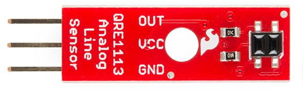
The Line Follower sensor is an add-on for your RedBot that gives your robot the ability to detect lines or nearby objects. The sensor works by detecting reflected light coming from its own infrared LED. By measuring the amount of reflected infrared light, it can detect transitions from light to dark (lines) or even objects directly in front of it.
The sensor has a 3-pin header which connects directly to the RedBot Mainboard via female to female jumper wires. Use the included RedBot library to detect lines or objects. A mounting hole lets you easily connect one or more of these to the front or back of your robot chassis.
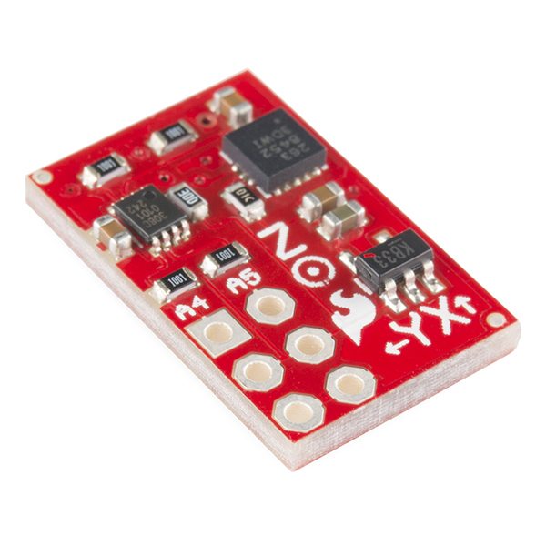
RedBot Accelerometer
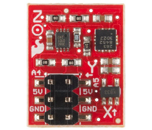
The Accelerometer sensor is an add-on for your RedBot that provides bump and motion detection. The sensor works by measuring acceleration forces on the x, y, and z axis. By measuring the amount of acceleration (or lack there of) your robot can get a better understanding of its movements.
The sensor has a 2x3 unpopulated footprint which connects directly to the RedBot Mainboard via a female header. You can also solder the sensor directly to the headers on the Mainboard if you wish.
RedBot Whisker Bumper
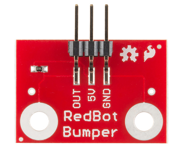
The Whisker Bumper is a very simple sensor comprised of a piece of music wire that closes a contact when bent and a circuit board to interface it to the RedBot. We ship the music wire straight, so you'll have to bend it to suit your application; the example shown above is only one way to do it.
RedBot Buzzer Board
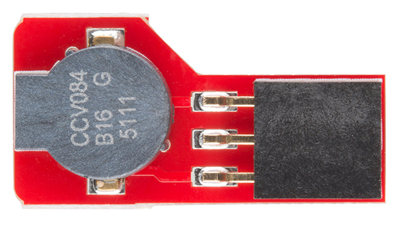
What's the fun of a robot that doesn't make beep-beep noises? We've made the RedBot Buzzer board to fit nicely on any header on the board, so you can integrate noise with your robot either just for fun or as a nice remote feedback function.
There's no special library support needed; just use the tone() family of commands already built into Arduino. One note: you can't use the Buzzer board on pins A6 and A7, as they are analog input-only pins.
Arduino Library
To help you make getting your robot moving as easy as possible, we've written an Arduino Library, which can be downloaded here. Here's a walk-through of the commands that the library provides. We'll see them in action later, with an example sketch. If you need a refresher on how to install an Arduino library, please see our library tutorial.
RedBot SoftwareSerial
The RedBot library includes a re-implementation of the SoftwareSerial library that comes with Arduino. This was necessary to integrate the other sensor functions with the interrupts that drive the SoftwareSerial library.
If possible, it's best to use the hardware serial port for interfacing with the XBee. There may be times where that is undesirable, however, so software serial support is provided.
For the most part, RedBotSoftwareSerial behaves just like normal SoftwareSerial, with a couple of exceptions:
- You no longer have a choice of which pins to use--the library always uses A0 and A1, which are the pins connected to the XBee module footprint.
- Incoming data is not reliable above 38400bps. Data transmission still works at higher speeds.
- Since the incoming data reception shares an interrupt with the sensors on the board, incoming data may be missed if other inputs are in use. In particular, incoming serial data may interfere with bump sensor detection or encoder counts, and incoming encoder data and bump sensing may interfere with serial data reception.
Motor Functions
The RedBotMotors class within the library provides control over all basic motor functionality. You should find it very easy to control your robot's motion using this command set.
language:cpp
RedBotMotors();
The constructor for the class, which is used to create a class object that can be referred to later, accepts no parameters. It will automatically configure all the peripherals and I/O lines you need to drive the motors. For example, creating an instance of the the RedBotMotors named motor
RedBotMotors motor;
will allow you to call all of the other functions from that class. Such as
motor.drive(255);
Now, let's go over some of the functions that live within that class.
void drive(int speed);
void rightDrive(int speed);
void leftDrive(int speed);
The three drive commands cause the motors to start turning. drive() starts both motors at (approximately) equal speeds; rightDrive() and leftDrive() activate their appropriate motors. Sign is important; positive speeds go forward, negative speeds go backwards. The range of speeds is from 0-255, although speeds below about 75 may not provide enough torque to start the motor turning. If you want very slow motion, try starting at a higher speed, then turning the speed down a bit.
void pivot(int speed);
Pivot turns the robot on its axis by spinning one motor one way and the other the opposite direction. Positive values correspond to anti-clockwise rotation; negative values to clockwise rotation.
void stop();
void rightStop();
void leftStop();
These commands discontinue the PWM output to one or both motors. The motors will continue to coast for a short time after this command is issued; if you need to stop quickly, use...
void brake();
void rightBrake();
void leftBrake();
Brake actually effectively shorts the terminals of the motors together, causing them to stop turning much faster than the stop() commands do. After a brake() has been issued, the wheels will also be much harder to turn, allowing the robot to hold position against a slope.
Line Sensor
The RedBotSensor class supports the line following sensors included in the kit.
RedBotSensor(int pin);
Pass the constructor the name of the pin to which the sensor is attached, and the library will take care of the rest.
void setBGLevel();
void setDetectLevel();
The level setting commands take stock of the surface the sensors are over at the moment and try to characterize it, so the detection of a transition can be automated. For example, if your robot is going to try to follow a black line on a white surface, run setDetectLevel() while the sensor is looking at the line, and setBGLevel() while the sensor is not looking at the line. The library will attempt to figure out a good rule for calling an edge having been seen.
boolean check();
Returns true if the current reading is consistent with the levels determined during the setDetectLevel() call, and false otherwise.
int read();
Returns the analog level of the sensor, if you prefer to do your own processing on the data.
Accelerometer
Another sensor provided for the RedBot is a specially designed accelerometer board. This board couples a Freescale MMA8452Q accelerometer with a TI PCA9306 level shifter and is designed to attached directly to the A4/A5 header on the RedBot. In addition to normal accelerometer data collection, it can be used to detect bumps (as in collisions) or taps (for user input).
RedBotAccel();
The class constructor accepts no parameters; simply instantiate an object of the class and the library will handle all necessary configuration. Including the I2C library provided by Arduino is not necessary either; all that is handled by the library.
void read();
Unlike most read-type functions, read() does not actually return a value. What it does is copy the most recent accelerometer values into three variables (naturally enough, named x, y and z. Those values can then be easily referred to using the class object name.
void enableBump();
boolean checkBump();
void setBumpThresh(int xThresh);
These three functions allow the user to enable and check bump detection. Under normal circumstances, the setBumpThresh() function shouldn't be needed; the bump threshold is already set to a good value. Users may find it useful to increase or decrease the sensitivity level; the range for that number is 0-127.
checkBump() returns a true if a bump has been detected since the last time checkBump() was called. It may be useful to call checkBump() to clear any existing bumps before attempting to detect a bump for decision making purposes, as the bump flag will remain set until it is read.
Whisker Bumper
RedBotBumper(int pin);
RedBotBumper(int pin, &bumpHandler);
The only two functions that the RedBotBumper class supports are constructors; by default, calling the first constructor will cause any falling edge on pin to stop the motors, and calling the first constructor will cause a falling edge on pin to call function bumpHandler(), where bumpHandler() is a user created function which accepts no parameters and returns no values.
Note that bumpHandler() is just a placeholder; you can tie the bump event to any function you want, and can have multiple pins tied to multiple different bump handling functions (so long as they have different names, of course).
Also note that the 'bumpHandler()' function executes in interrupt time. If that doesn't mean anything to you, here's what you need to know: functions like delay(), millis(), and serial reads/writes/prints will not work properly if you call them within bumpHandler(). It's best to do something simple in bumpHandler(), like set a flag, and then deal with the ramifications of that flag in the main code loop.
Example
This example uses the RedBot kit hardware and the RedBot library to realize a simple line following robot. We'll break the code down, bit by bit, and analyze it.
The sketch is included with the library located on the Github site, or you can download it here. Copy the folder in the "libraries" directory into your Arduino Sketchbook.
Here is the file if you'd like to check it out without downloading it. For more explanation on what is going on, check out the comments in the sketch.
language:c
// Include the library.
#include <RedBot.h>
#include <Servo.h>
#include "notes.h"

// Instantiate the motors.
RedBotMotors motors;

// Instantiate the accelerometer. It can only be connected to pins A4
//  and A5, since those are the I2C pins for this board.
RedBotAccel xl;

// Instantiate our encoder.
RedBotEncoder encoder = RedBotEncoder(A2, A3); // left, right

// Instantiate the sensors. Sensors can only be created for analog input
//  pins; the accelerometer uses pins A4 and A5. Also, since A6 and A7
//  can *only* be used as analog inputs, that's a good place for these.
RedBotSensor lSen = RedBotSensor(A6);
RedBotSensor rSen = RedBotSensor(A7);

// Instantiate a couple of whisker switches. Call bump() when one of them
//  hits something. There's no stopping you having a different function for
//  each whisker; I just chose not to.
RedBotBumper lBumper(10, &bump);
RedBotBumper rBumper(11, &bump);

// Instantiate a software serial port. Note that the regular Arduino
//  SoftwareSerial won't work! It steals resources that the sensor
//  inputs on the RedBot need. Also note that the RedBot version has
//  no input options- it automatically connects to the pins used for
//  the onboard XBee header.
RedBotSoftwareSerial swsp;

// Instantiate a servo- this is outside of the RedBot library!
Servo servo;

// Create an alias for our beeper pin, for ease of use.
#define BEEPER 9

// Create an alias for the onboard pushbutton.
#define BUTTON_PIN 12

// Create an alias for the onboard LED.
#define LED_PIN 13

// Constants for the levels that determine detection of the line.
const int bgLevel = 600;
const int lineLevel = 700;

// Flag for bumpers to send the signal that something's wrong and the motors should
//  be disabled for now. Set in the bump functions, volatile so the change is sure
//  to propagate to the loop() function.
volatile boolean bumped = true;

void setup()
{
  // We *probably* won't see the hardware serial data; what good is a robot
  //  that has to be tethered to a computer?
  Serial.begin(57600);
  Serial.println("Hello world!");
  // Set up our two built-in IO devices- the button and the LED.
  pinMode(BUTTON_PIN, INPUT_PULLUP);
  pinMode(LED_PIN, OUTPUT);
  // Play a tone for audible reset detection.
  tone(BEEPER, 2600, 750);
  delay(750);
  // Send out a hello via the XBee, if one is present.
  swsp.begin(9600);
  swsp.print("Hello, world");
  servo.attach(3);
}

void loop()
{
  // These static variables will be initialized once, then remain valid
  //  through each iteration of the loop.

  // Two loop timers; we have one loop that happens four times a second
  //  and one that happens ten times a second.
  static unsigned long loopStart = millis();
  static unsigned long loopStart2 = millis();
  // We're doing a crude low-pass filter on the accelerometer; we want
  //  two consecutive high values so we don't trigger our surprise on
  //  transient events, only on a significant change in angle.
  static int lastXAccel = xl.x;
  // These two variables handle the current position and position
  //  change of the scanning servo motor.
  static int angle = 0;
  static int angleDelta = 5;

  // Wait for the button to be pressed, then turn off the "bumped" flag
  //  so the motors can run. Also, clear the encoders, so we can track
  //  our motion.
  if (digitalRead(BUTTON_PIN) == LOW)
  {
    bumped = false;
    encoder.clearEnc(BOTH);
  }
  // Dump the current distance count on the right wheel to the serial
  //  port, just for something to do.
  swsp.println(encoder.getTicks(RIGHT));
  // If we pass 75 ticks on the right wheel, treat that the same as we
  //  would a bumper hit and stop moving.
  if (encoder.getTicks(RIGHT) > 75) bumped = true;

  // This is our ten-times-a-second loop. It's watching the accelerometer
  //  and, when the bot senses an incline, setting off our surprise.
  if (loopStart2 + 100 < millis())
  {
    loopStart2 = millis();
    lastXAccel = xl.x;
    xl.read();
    if (!bumped)
    {
      if (xl.x > 6000 && lastXAccel > 6000)
      {
        motors.brake();
        horn();
        motors.drive(255);
        delay(5000);
        motors.brake();
        bumped = true;
      }
    }
  }

  // This is the four-times-a-second loop. It scans a servo from left to
  //  right and back again.
  if (loopStart + 250 < millis())
  {
    loopStart = millis();
    servo.write(angle);
    if (angle + angleDelta > 120) angleDelta *= -1;
    if (angle + angleDelta < 0 ) angleDelta *= -1;
    angle += angleDelta;
  }

  // All this line-follow-y stuff should only be invoked when we are clear to move;
  //  if one of the bump sensors was set off, we should stay still until the user
  //  intervenes for us.
  if (!bumped)
  {
    // Line following code: turn away from any sensor that is above the line
    //  threshold.
    // Case 1: both white. Drive forward!
    if (lSen.read() < bgLevel && rSen.read() < bgLevel) motors.drive(100);
    // Case 2: right sensor is on black. Must recenter.
    if (rSen.read() > lineLevel)
    {
      motors.rightDrive(-100);
      motors.leftBrake();
    }
    // Case 3: left sensor is on black. Must recenter.
    if (lSen.read() > lineLevel)
    {
      motors.leftDrive(-100);
      motors.rightBrake();
    }
    // Case 4: both sensors see dark
    if (lSen.read() > lineLevel && rSen.read() >lineLevel)
    {
      motors.leftDrive(-100);
      motors.rightDrive(-100);
    }
  }
  else motors.brake();
}

// This is the function that gets called when we bump something. It
//  stops the motors, signals that a bump occurred (so loop() doesn't
//  just start the motors back up), and issues a nasty little tone to
//  tell the user what's up.
void bump()
{
  motors.brake();
  bumped = true;
  tone(BEEPER, 150, 750);
}

// This is all for our surprise. SN is the length of a sixteenth note,
//  in milliseconds, and EN is the length of an eighth note.
const int SN = 100;
const int EN = 200;
void horn()
{
  tone(BEEPER, noteG5, SN);
  delay(SN);
  tone(BEEPER, noteE5, SN);
  delay(SN);
  tone(BEEPER, noteC5, EN);
  delay(EN);
  tone(BEEPER, noteC5, EN);
  delay(EN);
  tone(BEEPER, noteC5, SN);
  delay(SN);
  tone(BEEPER, noteD5, SN);
  delay(SN);
  tone(BEEPER, noteE5, SN);
  delay(SN);
  tone(BEEPER, noteF5, SN);
  delay(SN);
  tone(BEEPER, noteG5, EN);
  delay(EN);
  tone(BEEPER, noteG5, EN);
  delay(EN);
  tone(BEEPER, noteG5, EN);
  delay(EN);
  tone(BEEPER, noteE5, EN);
  delay(EN);
}
Resources and Going Further
Get moving!
Hopefully, this guide has given you enough information to get started with the RedBot. Look for more sensors, kits and content around the RedBot platform!
Once you've mastered the art of line following robots, try you hand at other types of robots.
- You could use a robotic claw and a pan/tilt bracket to design a robot with an arm to fetch items for you.
- Learn more about the MMA8452Q accelerometer in the MMA8452Q Accelerometer Hookup Guide.
- You could create your own remote control using various SparkFun parts.
- And, you can always give your robot a new look with different types of robot chassis.
- Also, check out our HUB-ee Buggy tutorial for more robot ideas.