Cryptographic Co-Processor ATECC508A (Qwiic) Hookup Guide
 QCPete
Hardware Overview
Power
There is a power status LED to help make sure that your Cryptographic Co-processor Breakout is getting power. You can power the board either through the polarized Qwiic connector system or the breakout pins (3.3V and GND) provided. This Qwiic system is meant to use 3.3V, be sure that you are NOT using another voltage when using the Qwiic system.
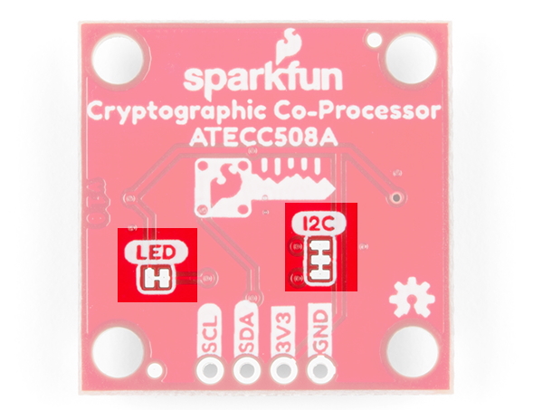
LED
The board includes a red power LED to indicate you have power plugged in properly. Note, there is a jumper on the back to disconnect this from the circuit. This is useful if you really want to conserve current consumption on your system.

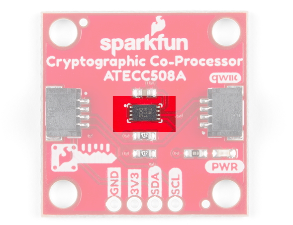
ATECC508A Cryptographic Co-Processor
The co-processor on this board is the Microchip ATECC508A. It's primary features include creating/storing ECC keys, creating digital signatures and verifying them. It is also capable of doing many other cryptographic processes includeing SHA-256 hash, Diffie-Hellman Key Exchange, and high quality random number generation. For more details on the ATECC508A cryptographic chip, check out the datasheet.
| Characteristic | Description |
|---|---|
| Operating Voltage | 2.0V to 5.5V (Default on Qwiic System: 3.3V) |
| Current Draw |
Active: 3 to 16 mA Idle: 800 µA Sleep: 30 to 150 nA |
| Operating Temperature | -40 to 85°C |
| EEPROM Storage |
Capacity: 10 Kb Data Retention: >10 years Write Endurance: 400,000 cycles |
| Configurable I2C Address (7-bit) | 0x60 (Default) |
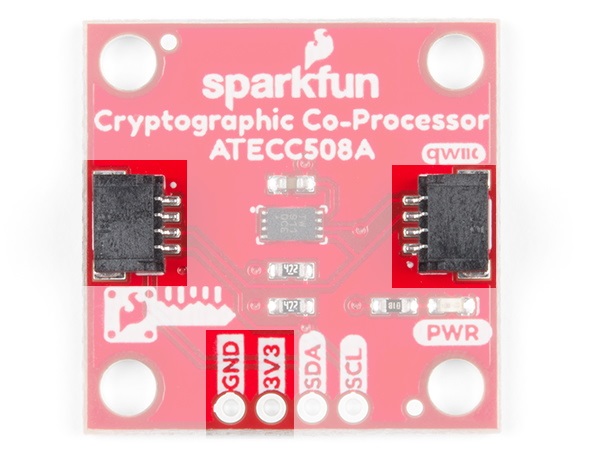
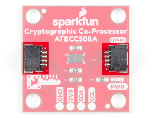
Connections
We've included two qwiic connectors for plug and play operation.
It also has the pins broken out to 0.1-inch PTH headers, if you'd like a more permanent (soldered) connection to the I2C lines.
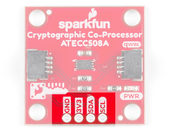
| Pin Label | Pin Function | Input/Output | Notes |
|---|---|---|---|
| 3.3V | Power Supply | Input | 3.3V on Qwiic system. |
| GND | Ground | Input | Ground |
| SDA | I2C Data Signal | Bi-directional | Bi-directional data line. |
| SCL | I2C Clock Signal | Input | Master-controlled clock signal. |
Jumpers
There are two jumpers on this board. The first, connects pull-up resistors to the I2C bus and the other connects the power to the PWR status LED.
| Name | Description | Usage |
|---|---|---|
| I2C | I2C Pull-Up Resistors | Opening these disables theI2C pull-up resistors used for I2C communication. If multiple I2C devices are being used, these pull-ups should be disabled on all but one device. If these pins (SDA/SCL) are being used for other purposes (UART, LEDs, GPIO), the pull-up resistors should usually be disabled. |
| LED | Enable/Disable LED | Cut this jumper to disconnect the LED and save power! |
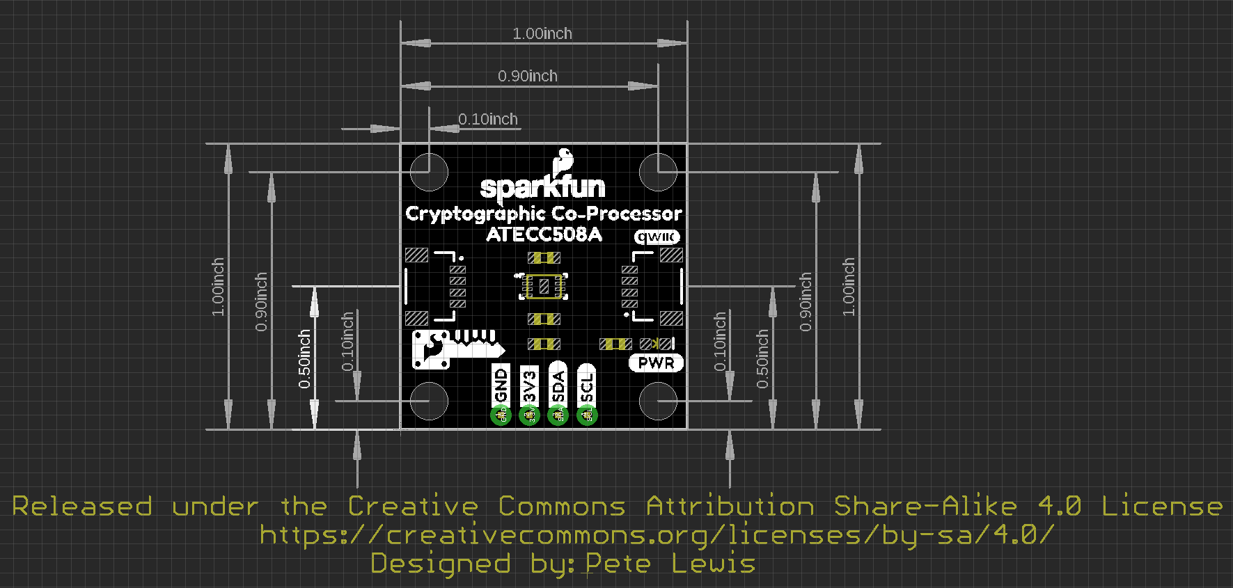
Board Dimensions
For those interested, the basic board dimensions are shown below, all measurements are in inches and the grid spacing is 0.1". The SparkFun Cryptographic Co-processor PCB itself, measures (approximately) 1x1 inch. Additionially, we have provided a PDF of the dimensional drawing, if necessary.