Cryptographic Co-Processor ATECC508A (Qwiic) Hookup Guide
 QCPete
 Introduction
🔒 Note: Please follow through the hookup guide in its entirety before using this board. The chip cannot be re-configured after it is PERMANENTLY locked.
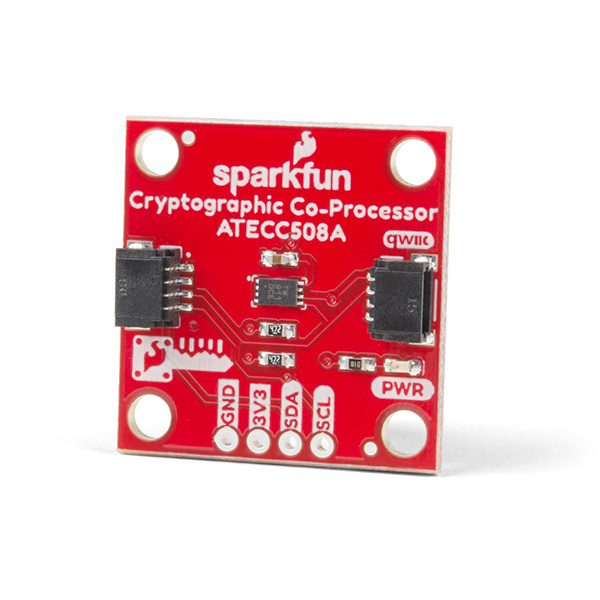
The SparkFun Cryptographic Co-processor Breakout ATECC508A (Qwiic) takes all the great features of the Microchip ATECC508A Cryptographic Authentication Device and adds two Qwiic ports for plug and play functionality. In this tutorial we will cover the fundamentals of cryptographic authentication and how to use the ATECC508A to add a very high level of security to your projects.
The ATECC508A is capable of many cryptographic processes. This tutorial focuses on Elliptic-curve cryptographic digital signatures (ECC) - using asymetric private/public keys. If those last few words are new to you, please read on! We will spend some time explaining in a bit.
🔒 Note:This chip is NOT capable of encrypting and decrypting data. It can however, perform quite a few cryptographic authentication processes such as secure private key creation, secure key storage and digital signature creation and verification.
At a very high level, the purpose of using this chip is to (1) verify that the message received actually came from the true sender and (2) verify that the data received was not tampered with. This technology is used in hyper-critical devices such as rocket launches, medical devices, two factor authentication keys (2FA), ink cartridges, garage door openers and car key FOBs.
Probably it's most important feature: this device can securely store a private ECC key. In fact, this private key will never be accessible - not even to you, the owner. It is created internally on the chip during configuration, and it can never be read from the chip (even if your de-capped the chip). Although you will never know it, you can still command the co-processor to use the secret private key to create a unique signature on some data. With this functionality, it can be used to securely authenticate a message in any kind of communication system. For example, between systems such as a node in an IoT system. Follow along, and you'll be creating 64 byte signatures (yes, bytes) and verifying them securely in no time!
Required Materials
To follow along with this tutorial, you will need the following materials that are included in the kit. You may not need everything though depending on what you have. Add it to your cart, read through the guide, and adjust the cart as necessary.
Note: To follow this tutorial, an Artemis microcontroller board has to be used with this product due to the buffer size required for the I2C bus.
For more advanced users, other microcontrollers can be used, but the buffer size of Wire library and/or the syntax for the serial print statements will need to be modified. (*This is outside the scope of this tutorial.)
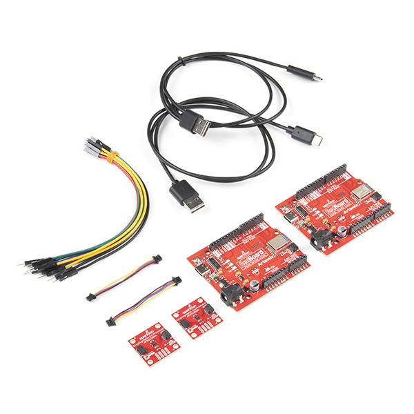
SparkFun Cryptographic Development Kit
KIT-18303Suggested Reading
If you aren’t familiar with the following concepts, we recommend you read over these tutorials before continuing.
Serial Communication
I2C
Artemis Development with Arduino
Hookup Guide for the SparkFun RedBoard Artemis
Cryptographic Authentication
Cryptography is a large subject matter. There many different types of cryptographic processes, each with their own different purpose and type of math. In this tutorial, we are focusing on cryptographic authentication. On a very high level, this usually involves data, digital signatures and verification. First, we must understand what a digital signature is and how it is created. Second we must understand verification which includes the use of a private/public key pair. Let's jump into digital signatures!
Digital signatures
A digital signature is quite similar to a hand-written signature. After you write a letter, you add your signature at the bottom. Just like the hand-written signature, a digital signature is added to your data. When we say "added" we mean that it is included as a separate chunk of data. So when sending some data with a digital signature, you would send the data as one piece of data, and then you would also send the digital signature as a separate piece of data. So this is the first difference to understand: digital signatures are like hand-written signatures, except they don't live on the same piece of paper (they are a separate chunk of data).
Another big difference: to create a digital signature, you need a bit more than a pen. You actually need three things:
- Data: This is the data you want to sign. For this co-processor, we are going to sign 32 bytes of data. This is essentially your "letter without a signature".
- A Key: Is simply a unique chunk of data. The key lives on a protected part of the co-processors memory. It was created during configuration. We will never have access to it. The idea of a single digital key is pretty straight forward. It parallels the physical door key quite well. The chunk of data is unique, just like the grooves and cuts of a physical key are unique.
- An Algorithm: The complex math that we will offload to the co-processor. It is a particular type of cryptographic math called Elliptic Curve Cryptography (ECC). Using our data and key, this algorithm will output a digital signature.
One more thing: digital signatures will be different when you change your message. This is pretty different than the traditional idea of a signature. When we think of hand-written signatures, we think that the entire purpose is for it to be exactly the same every time. The author should be the only one who can hold the pen like so and make that unique signature. With digital signatures we need to think a bit differently. Remember that we are sending our message (and a key) into an algorithm. This will result in a new and different signature if the message or key changes. In most cases, a digital signature is always unique from all other previous digital signatures.
So that was easy enough, right? Good. Digital signatures aren't so scary now. But what would we want to do with one of these? Verify it.
Verification
Verification of a digital signature is quite similar verifying a hand-written signature. In both cases, we want to determine if the signature is authentic. With a hand-written signature, you might just use your eyes to see if it looks correct. With a digital signature we need to use a bit more than our eyes. We need the data, the signature, a key, and an algorithm (sound familiar?). Simple enough, right? Well this is where it starts to get slightly more complex. We need to understand one more concept: the idea of key pairs.
Up until this point, we have called the "key" simply a "key", but to be more accurate, this should be called the private key. And it is part of a key pair. When we configure the co-processor it actually creates a key pair which includes two keys: one private key and one public key. These two keys work together, and they allow us to sign and verify signatures. We use the private key to sign the data, and we use the public key to verify data. This is also known as an asymetric cryptographic process.
Now that we're talking private and public key pairs, let's clearly define what we need to create a digital signature, and what we need to verify a digital signature:
| To create a digital signature we need: | To verify a digital signature we need: |
|---|---|
|
1. Data 2. Private Key 3. Algorithm |
1. Data 2. Signature 3. Public Key 4. Algorithm |
| Algorithm output: a new digital signature | Algorithm output: yes or no |
From Alice to Bob
Although you can accomplish a few neat things using only one of these chips (signing data, verifying signatures, creating high-quality random numbers, etc.), the truly powerful communication security starts when you have two of them (we will refer to them as Alice and Bob).
Our Arduino library utilizes the old story of Alice, Bob and Eve. If you read up on cryptography, you will often come across these names. Alice and Bob are always trying to have a private conversation, but Eve keeps eavesdropping (and sometimes trying to impersonate Alice). So Alice and Bob start using cryptography to keep Eve out of the mix.
Side note: In a lot of traditional examples, Alice and Bob are encrypting and decrypting their messages. I want to highlight here again, that this chip utilizes a different cryptographic tool: authentication. With the ATECC508A, we can create and verify signatures. The message is still sent out in the open/public for Eve to clearly read. However, Eve will never have Alice's private key and could never create a valid signature (to authenticate the message). Therefore, Eve can never pretend to be Alice!
In our examples, Alice is sending a message to Bob. Alice can use her own co-processor to create a digital signature. She can then send her message and signature to Bob. Bob can then use his own separate co-processor to verify the message and signature.

If you are brand new to cryptography, take a minute to watch the above gif loop a couple times. It shows the basic steps necessary to have an authenticated message from Alice to Bob. The use of a private/public key pair can be a bit daunting at first sight, but after going through this tutorial, we hope it can become a piece of cake.
Hardware Overview
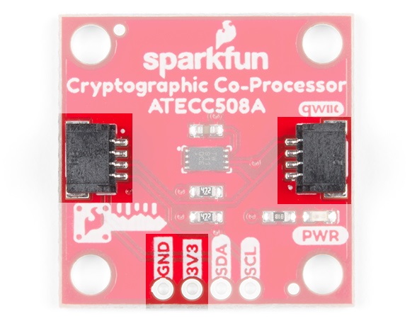
Power
There is a power status LED to help make sure that your Cryptographic Co-processor Breakout is getting power. You can power the board either through the polarized Qwiic connector system or the breakout pins (3.3V and GND) provided. This Qwiic system is meant to use 3.3V, be sure that you are NOT using another voltage when using the Qwiic system.
LED
The board includes a red power LED to indicate you have power plugged in properly. Note, there is a jumper on the back to disconnect this from the circuit. This is useful if you really want to conserve current consumption on your system.

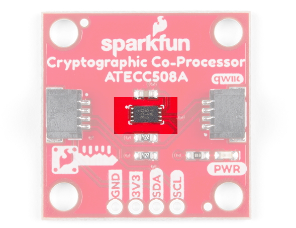
ATECC508A Cryptographic Co-Processor
The co-processor on this board is the Microchip ATECC508A. It's primary features include creating/storing ECC keys, creating digital signatures and verifying them. It is also capable of doing many other cryptographic processes includeing SHA-256 hash, Diffie-Hellman Key Exchange, and high quality random number generation. For more details on the ATECC508A cryptographic chip, check out the datasheet.
| Characteristic | Description |
|---|---|
| Operating Voltage | 2.0V to 5.5V (Default on Qwiic System: 3.3V) |
| Current Draw |
Active: 3 to 16 mA Idle: 800 µA Sleep: 30 to 150 nA |
| Operating Temperature | -40 to 85°C |
| EEPROM Storage |
Capacity: 10 Kb Data Retention: >10 years Write Endurance: 400,000 cycles |
| Configurable I2C Address (7-bit) | 0x60 (Default) |
Connections
We've included two qwiic connectors for plug and play operation.
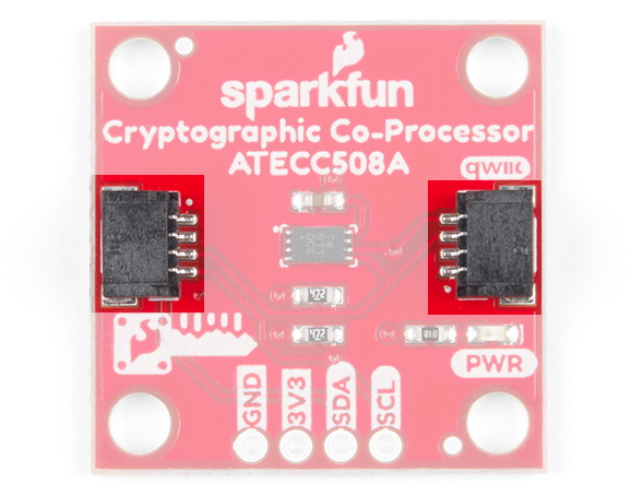
It also has the pins broken out to 0.1-inch PTH headers, if you'd like a more permanent (soldered) connection to the I2C lines.
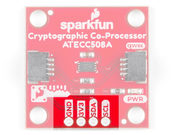
| Pin Label | Pin Function | Input/Output | Notes |
|---|---|---|---|
| 3.3V | Power Supply | Input | 3.3V on Qwiic system. |
| GND | Ground | Input | Ground |
| SDA | I2C Data Signal | Bi-directional | Bi-directional data line. |
| SCL | I2C Clock Signal | Input | Master-controlled clock signal. |
Jumpers
There are two jumpers on this board. The first, connects pull-up resistors to the I2C bus and the other connects the power to the PWR status LED.
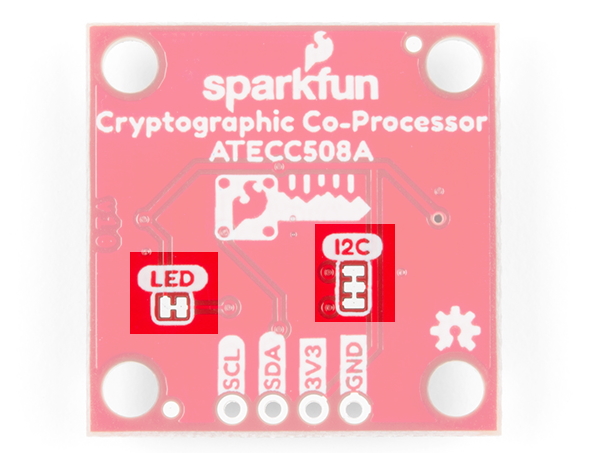
| Name | Description | Usage |
|---|---|---|
| I2C | I2C Pull-Up Resistors | Opening these disables theI2C pull-up resistors used for I2C communication. If multiple I2C devices are being used, these pull-ups should be disabled on all but one device. If these pins (SDA/SCL) are being used for other purposes (UART, LEDs, GPIO), the pull-up resistors should usually be disabled. |
| LED | Enable/Disable LED | Cut this jumper to disconnect the LED and save power! |
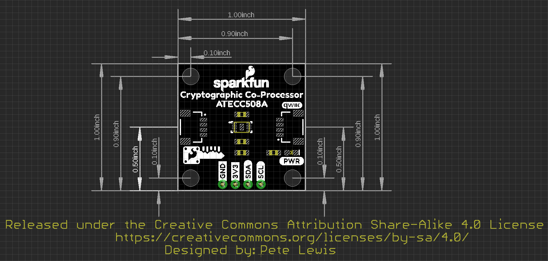
Board Dimensions
For those interested, the basic board dimensions are shown below, all measurements are in inches and the grid spacing is 0.1". The SparkFun Cryptographic Co-processor PCB itself, measures (approximately) 1x1 inch. Additionially, we have provided a PDF of the dimensional drawing, if necessary.
Hardware Hookup
Note: To follow this tutorial, an Artemis microcontroller board has to be used with this product due to the buffer size required for the I2C bus.
For more advanced users, other microcontrollers can be used, but the buffer size of Wire library and/or the syntax for the serial print statements will need to be modified. (*This is outside the scope of this tutorial.)
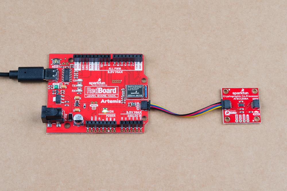
With the Qwiic connector system, assembling the hardware is fairly simple. For the examples below, all you need to do is connect your Cryptographic Co-Processor Breakout to a RedBoard Artemis with a Qwiic cable. Otherwise, you can use the I2C pins, if you don't have a Qwiic connector on your microcontroller board. Just be aware of your input voltage and any logic level shifting you may need to do. (*Don't forget to plug the Artemis into a computer with a USB-C cable.)
Note, the setup shown here is used for the configuration example and the single-board examples (1,2,3 and 5). For the more advanced examples that involve Alice and Bob (Example 4 and Example 6), you will need to setup two Artemis boards - each with their own co-processor. Additional hardware hookup instructions are included at those sections.
Software Setup
Note: This tutorial assumes you are using the latest stable version of the Arduino IDE on your desktop. If this is your first time using Arduino, please review our tutorial on installing the Arduino IDE. If you have not previously installed an Arduino library, please check out our installation guide.
Installing Arduino
If you haven't used the Arduino IDE before, head on over to our Installing the Arduino IDE tutorial to get set up:
Installing Arduino IDE
Getting the Arduino Library
To make Configuration and start using your Cryptographic Co-processor, we have written an Arduino Library. It currently supports only the Artemis board family. This is because some of the commands to the Co-processor require a larger I2C buffer. You have two options to install this library:
- Use the library manager or install in the Arduino IDE
We recommend using the library manager to tool within the Arduino IDE (Sketch > Include Library > Manage Libraries...). In the Library Manager, search for Sparkfun_Cryptographic. For help installing the library, check out our How to Install an Arduino Library tutorial.
Installing an Arduino Library
How do I install a custom Arduino library? It's easy! This tutorial will go over how to install an Arduino library using the Arduino Library Manager. For libraries not linked with the Arduino IDE, we will also go over manually installing an Arduino library. - Download the Github repository
Users can also manually download and install the library from Github. You can Visit the GitHub repository to download the most recent version of the library, or click the link below:
Setting up the Artemis Board
In case you haven't checked out the hookup guide for the RedBoard Artemis, we suggest reviewing it as the features are very different from your standard Arduino Uno.
Installing Artemis Board Package
This tutorial and Arduino Library support the Artemis Boards. You will need to use the Boards manager to install the necessary packages. You can visit the specific section of the Artemis tutorial here, or read the entire tutorial in the link below:
Artemis Development with Arduino
CH340 Driver Installation for the RedBoard Artemis
Don't forget, if you've never connected an CH340 device to your computer before, you may need to install drivers for the USB-to-serial converter. Check out our section on How to Install CH340 Drivers for help with the installation.
How to Install CH340 Drivers
Arduino Library
Note: This code/library has been written and tested on Arduino IDE version 1.8.10. Otherwise, make sure you are using the latest stable version of the Arduino IDE on your desktop.
If this is your first time using Arduino, please review our tutorial on installing the Arduino IDE. If you have not previously installed an Arduino library, please check out our installation guide.
We've written a library to easily get setup and start using the Cryptographic Co-processor ATECC508A. If you'd like to jump right into signing and verifying, then feel free to skip ahead to Example 1: Configuration However, it's not a bad idea to familiarize yourself a bit with the source code behind the examples, so let's take a closer look at the available functions in the library. You can install this library through the Arduino Library Manager. Search for SparkFun_Cryptographic and you should be able to install the latest version. If you prefer manually downloading the libraries from the GitHub repository, you can grab them here:
Let's get started by looking at the functions that set up the ATECC508A.
Setup
.begin() or .begin(i2caddr, TwoWire)
Creates a connection to an I2C device over the I2C bus using the default or specified I2C address.
Unassigned 7-bit integer for device address. If not defined, the library will use the default I2C address stored in the I2C library (0x60). This can be changed by writing the I2C address to the specific Configuration Zone address (byte 16) prior to locking that zone.
Input: WireWire port assignment. If not defined, the library will use the default Wire port. (*This is only available to change on boards that in fact have multiple Wire Ports (i.e. Artemis). Currently, only the default wire port located on the Qwiic connector is supported on the Artemis.)
Output: BooleanTrue- Connected to I2C device on the default (or specified) address.
False- No device found or connected.
Communication
.wakeUp()
Checks to see if a device over the I2C bus is connected. Returns boolean true or false depending on if the slave device has correctly ACK'd to an I2C request and responded with the correct "wake verification" response: 0x11.
True- Device present on the default (or specified) address.
False- No device found or transmission error.
.idleMode()
The ATECCX08A goes into the idle mode and ignores all subsequent I/O transitions until the next wake flag. The contents of TempKey and RNG Seed registers are retained. (*Idle Power Supply Current: 800uA.)
Note, it will automatically go into sleep mode after watchdog timer has been reached (1.3-1.7sec).
.receiveResponseData(uint8_t length, boolean debug)
This function receives messages from the ATECCX08a IC (up to 128 Bytes). It will return true if it receives the correct amount of data and good CRCs. What we hear back from the IC is always formatted with the following series of bytes:
COUNT, DATA, CRC[0], CRC[1]
Note, the count number includes itself, the num of data bytes, and the two CRC bytes in the total, so a simple response message from the IC that indicates that it heard the wake condition properly is like so:
EXAMPLE Wake success response: 0x04, 0x11, 0x33, 0x44
Unassigned 8-bit integer.
Length of data in bytes (max 32 bytes).
Includes: Count + DATA + 2 CRC bytes.
True- Communication complete and message count and CRC are good.
False- Communication failure (count error, CRC error, or no device present)
.checkCount(boolean debug)
This function checks that the count byte received in the most recent message equals countGlobal. Users must call .receiveResponseData and then immediately call this to check the count of the complete message.
True- count received and count calculated match (aka inputBuffer[0] == countGlobal)
False- Count error, message invalid.
.checkCrc(boolean debug)
This function checks that the CRC bytes received in the most recent message equals calculated CRCs. Users must call .receiveResponseData then call immediately call this to check the CRCs of the complete message.
True- CRC received and CRC calculated match (aka inputBuffer[0] == countGlobal)
False- CRC error, message invalid.
.atca_calculate_crc(uint8_t length, uint8_t *data)
This function calculates CRC. It was copied directly from the App Note provided from Microchip (*it seems to be their own unique implementation of CRC cacluation.).
You're CRC bytes will be located for use at global public variable .crc.
Unassigned 8-bit integer. Length number of bytes in buffer.
Unassigned 8-bit integer. Data to be used in the CRC calculation.
.sendCommand(uint8_t command_opcode, uint8_t param1, uint16_t param2, uint8_t *data, size_t length_of_data)
This function handles creating the "total transmission" to the IC.
This contains WORD_ADDRESS_VALUE, COUNT, OPCODE, PARAM1, PARAM2, DATA (optional), and CRCs.
Note, it always calls the
wake() function, assuming that you have let the IC fall asleep (default 1.7 sec)Note, for anything other than a command (reset, sleep and idle), you need a different "Word Address Value",
So those specific transmissions are handled in unique functions.
Unassigned 8-bit integer.
COMMAND_OPCODE_INFO - Return device state information.
COMMAND_OPCODE_LOCK - Lock configuration and/or Data and OTP zones.
COMMAND_OPCODE_RANDOM - Create and return a random number (32 bytes of data).
COMMAND_OPCODE_READ - Return data at a specific zone and address.
COMMAND_OPCODE_WRITE - Return data at a specific zone and address.
COMMAND_OPCODE_GENKEY - Create a public and/or private key and store it in a slot.
COMMAND_OPCODE_NONCE - Generates a nonce for use by a subsequent command.
COMMAND_OPCODE_SIGN - Create ECC signature with TempKey and designated private key.
COMMAND_OPCODE_VERIFY - Verify an ECDSA (R,S) signature against data and public key.
Unassigned 8-bit integer. Unique to each command.
Unassigned 16-bit integer. Unique to each command.
Unassigned 8-bit integer pointer. Unique to each command.
Unassigned 8-bit integer. Unique to each command.
.read(uint8_t zone, uint16_t address, uint8_t length, boolean debug)
Your data response will be available at
.inputBuffer.
Unassigned 8-bit integer.
Zone to be read from.
ZONE_CONFIG - Configuration Zone.
ZONE_OTP - One Time Programming Zone.
ZONE_DATA - Data Zone (for keys and certificates).
Unassigned 16-bit integer.
Address within zone be read (must include modification for offset)
Unassigned 8-bit integer.
Length of data to be read (can only be 4 bytes or 32 bytes)
True- Communication complete and message count and CRC are good.
False- Communication failure or command execution failure.
.write(uint8_t zone, uint16_t address, uint8_t *data, uint8_t length_of_data)
Note, once a zone is locked, you can no longer write to it, and this function will return false.
Unassigned 8-bit integer.
Zone to be read from.
ZONE_CONFIG - Configuration Zone.
ZONE_OTP - One Time Programming Zone.
ZONE_DATA - Data Zone (for keys and certificates).
Unassigned 16-bit integer.
Address within zone be written to (must include modification for offset)
Unassigned 8-bit integer pointer.
Unassigned 8-bit integer.
Length of data to be written (can only be 4 bytes or 32 bytes)
True- Communication complete and message count and CRC are good.
False- Communication failure or command execution failure.
Configuration
.writeConfigSparkFun()
For key slots 0 and 1, this enables ECC private key pairs, public key generation, and external signature verifications.
True- All write commands were successful.
False- Communication failure or IC command execution failure.
.lockConfig()
0x00).
True- Lock command was successful.
False- Communication failure or IC command execution failure.
.lockDataAndOTP()
0x00).
True- Lock command was successful.
False- Communication failure or IC command execution failure.
.lockDataSlot0()
0x00).
True- Lock command was successful.
False- Communication failure or IC command execution failure.
.lock(uint8_t zone)
0x00).
Unassigned 8-bit integer.
LOCK_MODE_ZONE_CONFIG - Lock only the configuration data zone.
LOCK_MODE_ZONE_DATA_AND_OTP - Lock only the Data and OTP zones.
LOCK_MODE_SLOT0 - Lock only the KEYID data slot 0.
True- Lock command was successful.
False- Communication failure or IC command execution failure.
.readConfigZone()
It stores them for viewing in a large global public variable array called
.configZone (128 bytes).In addition to configuration settings, the configuration memory on the IC also
contains the serial number, revision number, lock statuses, and much more.
This function also updates global variables for these other things.
.createNewKeyPair(uint16_t slot)
in the slot designated by argument slot (default slot 0).
Sparkfun Default Configuration Sketch calls this, and then locks the data/otp zones and slot 0.
Unassigned 8-bit integer. The KEYID data slot you'd like it to be created in.
True- GENKEY command was successful.
False- Communication failure or IC command execution failure.
Sign and Verify
.createSignature(uint8_t *data, uint16_t slot)
Defauts to use private key located in slot 0.
Your signature will be available at global public variable
.signatureNote, the IC actually needs you to store your data in a temporary memory location
called TempKey. This function first loads TempKey, and then signs TempKey. Then it
receives the signature and copies it to signature.
Unassigned 8-bit integer pointer. (Max 32 bytes).
Unassigned 8-bit integer. The KEYID data slot you'd like to use for ECC calculation.
True- Both load tempKey and signTempkey commands were successful.
False- Communication failure or IC command execution failure.
.verifySignature(uint8_t *message, uint8_t *signature, uint8_t *publicKey)
Note, the IC actually needs you to store your message in a temporary memory location
called TempKey. This function first loads TempKey with the message, and then sends the verify command
with additional data paramaters: signature and publicKey. Then it listens for result from IC.
Unassigned 8-bit integer pointer. (32 bytes).
Unassigned 8-bit integer pointer. (64 bytes)
Unassigned 8-bit integer pointer. (64 bytes)
True- Both load tempKey and verify commands were successful.
False- Verification failure, Communication failure or IC command execution failure.
Random Number Generator
.random(long max)
Max can be up to the larges positive value of a long: 2147483647
Long. (1-2147483647)
.random(long min, long max)
Min and max can be positive or negative numbers.
Long. (-2147483647 to +2147483647)
Long. (-2147483647 to +2147483647)
.getRandomByte(boolean debug)
.getRandomInt(boolean debug)
.getRandomLong(boolean debug)
.updateRandom32Bytes(boolean debug)
It stores it in a global public variable array called
.random32BytesIf you wish to access this global variable and use as a 256 bit random number,
then you will need to access this array and combine it's elements as you wish.
True- Random command execution successful.
False- Communication failure or IC command execution failure.
Example 1: Configuration
🔒Warning: Configuration settings are PERMANENT. We would like to stress the fact that these cannot be changed later. If you intend to follow along with this tutorial, then configure with SparkFun standard settings.
If you intend to use different features of the co-processor like the Diffie-Hellman Key Exchange and some of its other use cases, please consider designing your own custom configuration. This hookup guide only focuses on digital signature creation and verification.
This example shows how to setup your Cryptographic Co-processor with SparkFun's standard settings. This will allow you to sign data and verify data with external signatures. The type of private keys we use in all of these examples are ECC. We have also included an example to use the random number generator and a challenge example. Beyond these functions, you may need to start with a different custom configuration.
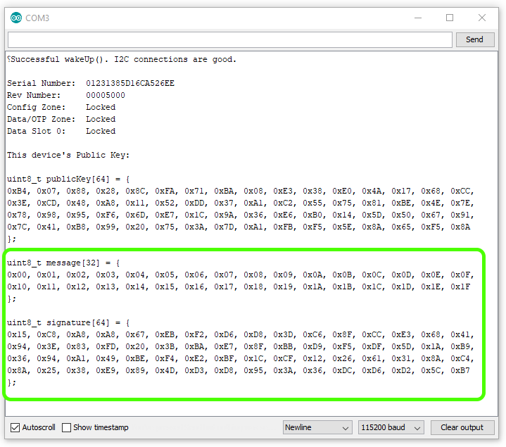
To configure, upload Example1_Configuration.ino and open a serial terminal at 115200 baud. If communication with a fresh chip is successful, your Artemis will print out some useful information about your chip.
It will then prompt you to type a y to configure your device. Note, if you do not wish to configure your device, you can simply unplug at this time. Also, did we mention yet, that if you type a y, there's no going back.
Example 2: Sign
This example shows how to create a digital signature. To try it out, simply upload the Example2_Sign.ino, and watch your serial terminal at 115200 baud. Note, you may need to hit reset.
Important things to know about ECC signatures:
ECC signatures are created using a secret private key and the elliptical curve algorithm. For the purpose of this example, we can just ignore the printout of the keys public key at the top - this is part of the
printInfo()function. As a side note, we will never know the devices private key. The private key for this device is created, stored and locked up inside the device.ECC signatures are 64 bytes long.
Contrary to most definitions of signatures, ECC signatures are different every time! ECCs include intentional randomness in the calculation, and so it will always produce a new unique signature. However, every signature that it creates will pass verification (as we will later see in example 3). Try hitting reset on your Artemis a few times and watch the signature values change.
Same message+same private key=new signature.With the ATECC508A, we can only send it 32 bytes of data to sign. If you need to sign something larger, then it is recommended that you create a 32-byte hash of the data first, then you can sign the hash. Basically, when you send a bunch of data into a hashing algorithm (such as SHA256), it will always respond with a unique 32 byte digest. It is very similar to creating a digital signature, however it does not require a key, so anyone can calculate the hash of any data. You may find that for many projects, 32 bytes is enough data, so for now, there's no need to pursue hashes.
The Code
Now lets take a quick look at the important parts of the example code. There are two things worthy of note:
At the very top, we define the message we want to sign.
language:c
// array to hold our 32 bytes of message. Note, it must be 32 bytes, no more or less.
uint8_t message[32] = {
  0x00, 0x01, 0x02, 0x03, 0x04, 0x05, 0x06, 0x07, 0x08, 0x09, 0x0A, 0x0B, 0x0C, 0x0D, 0x0E, 0x0F,
  0x10, 0x11, 0x12, 0x13, 0x14, 0x15, 0x16, 0x17, 0x18, 0x19, 0x1A, 0x1B, 0x1C, 0x1D, 0x1E, 0x1F
};
Not much to say here, other than it's a nice array of 32 unsigned 8 bit integers. We chose to make the values simply count from 0 to 32, but these could really be anything.
language:c
//Let's create a digital signature!
atecc.createSignature(message); // by default, this uses the private key securely stored and locked in slot 0.
Well, the comments say it all, but I will mention that by sending the argument "message", we are sending a pointer to the first index (0), of the array. createSignature actually does 4 things for us under the hood:
Loads the message into the co-processor's memory location on the chip called
tempKey.Commands the co-processor to sign the contents of tempKey.
Receives the 64 byte signature and stores it in a public variable accessible at
atecc.signature. Note, we created an instance of the ATECCX08A class with the nameatecc, but you could choose something different, and then you'd need to modify how you access this signature array.Prints a nice
ready to compileserial debug message showing the signature. Handy for copying and pasting between code.
Example 3: Verify
This Example shows how to verify a signature. In order for the co-processor to do this, it needs three things:
- Public Key (of the sender)
- Message
- Signature
If you have just completed Example2_sign, then you should remember seeing these 3 things printed out on the serial terminal. Before uploading Example3_verify.ino, please ensure you update the public key, message and signature at the top of the sketch.
Also very important: you will need to rename the publicKey[64] array at the top to publicKeyExternal[64]. This is what we will use to verify the message and signature, and so we must clarify that it is external.
Before uploading Example3_Verify.ino, we encourage you to click on the .gif below and watch a couple times. This can help show exactly what to do.
publicKey[64], message[32], and signature[64] from the output of Example2_sign.ino to operate Example3_Verify.ino. (Click to Enlarge) The Code
The fresh code that you see when you open up Example3_Verify.ino has place holders. Notice how all the bytes in each array is simply a bunch of 0x00s.
language:c
uint8_t publicKeyExternal[64] = {
0x00, 0x00, 0x00, 0x00, 0x00, 0x00, 0x00, 0x00, 0x00, 0x00, 0x00, 0x00, 0x00, 0x00, 0x00, 0x00,
0x00, 0x00, 0x00, 0x00, 0x00, 0x00, 0x00, 0x00, 0x00, 0x00, 0x00, 0x00, 0x00, 0x00, 0x00, 0x00,
0x00, 0x00, 0x00, 0x00, 0x00, 0x00, 0x00, 0x00, 0x00, 0x00, 0x00, 0x00, 0x00, 0x00, 0x00, 0x00,
0x00, 0x00, 0x00, 0x00, 0x00, 0x00, 0x00, 0x00, 0x00, 0x00, 0x00, 0x00, 0x00, 0x00, 0x00, 0x00
};

uint8_t message[32] = {
0x00, 0x00, 0x00, 0x00, 0x00, 0x00, 0x00, 0x00, 0x00, 0x00, 0x00, 0x00, 0x00, 0x00, 0x00, 0x00,
0x00, 0x00, 0x00, 0x00, 0x00, 0x00, 0x00, 0x00, 0x00, 0x00, 0x00, 0x00, 0x00, 0x00, 0x00, 0x00
};

uint8_t signature[64] = {
0x00, 0x00, 0x00, 0x00, 0x00, 0x00, 0x00, 0x00, 0x00, 0x00, 0x00, 0x00, 0x00, 0x00, 0x00, 0x00,
0x00, 0x00, 0x00, 0x00, 0x00, 0x00, 0x00, 0x00, 0x00, 0x00, 0x00, 0x00, 0x00, 0x00, 0x00, 0x00,
0x00, 0x00, 0x00, 0x00, 0x00, 0x00, 0x00, 0x00, 0x00, 0x00, 0x00, 0x00, 0x00, 0x00, 0x00, 0x00,
0x00, 0x00, 0x00, 0x00, 0x00, 0x00, 0x00, 0x00, 0x00, 0x00, 0x00, 0x00, 0x00, 0x00, 0x00, 0x00
};
You will need to delete these and paste in your own unique arrays. You could type them in manually, but it will be much easier to copy and paste them from the terminal output from Example 2.
Also note, when you highlight text within an Arduino serial monitor window, you must use the keyboard to actually copy them (Ctrl + C). It won't let you right-click to copy.
And the actual verification of the signature happens as a single function call. It is located at the bottom of setup().
language:c
// Let's verirfy!
if (atecc.verifySignature(message, signature, publicKeyExternal)) Serial.println("Success! Signature Verified.");
else Serial.println("Verification failure.");
atecc.verifySignature(message, signature, publicKeyExternal) is the actual call. This function will return a boolean true if all three things are good, and a false if something doesn't add up. If you change a single bit in any three of the arguments, then it won't verify.
Two nice things to thing about:
The only place in the world that could create the signature that will verify (using this public key) is inside your one unique co-processor. No one else in the world would ever be able to impersonate it. Pretty cool huh!
If any of the message was changed (even just a single bit flipped), then this verification would fail. This means that you can be very confident that the message was transmitted and received properly. In this way it is acting as a very robust checksum. It also means that if someone actually intercepted this message, they won't be able to change anything in the message. Sweet!
Example 4: From Alice to Bob
Example4_Alice.ino and Example4_Bob.ino. You will need to use both of these to complete this Example. We recommend opening two separate instances of Arduino, this way you can setup each one with its own com port for uploading and serial terminal.
Hardware hookup
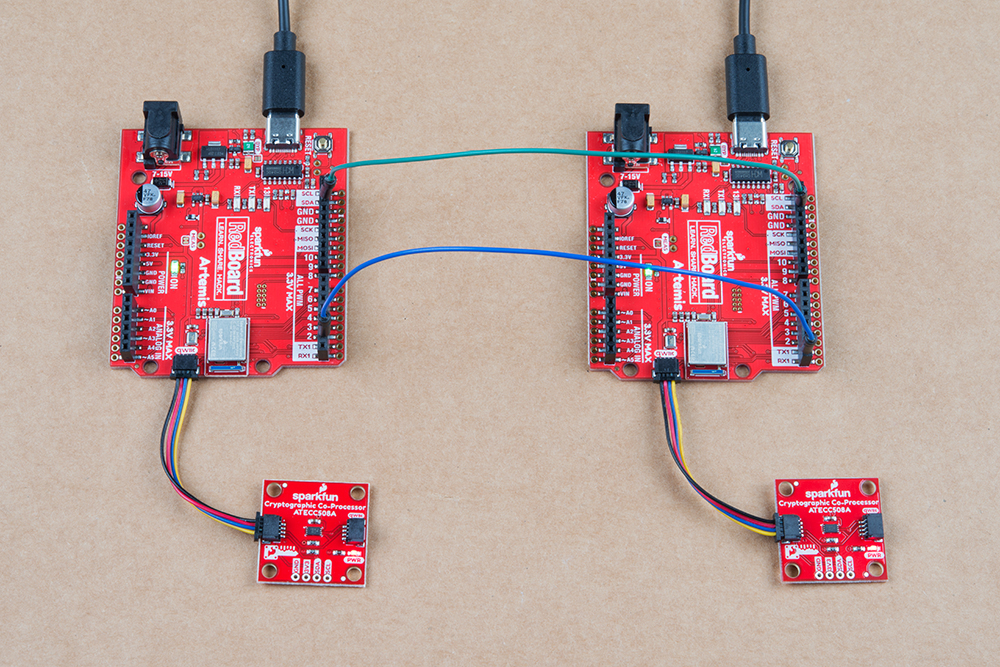
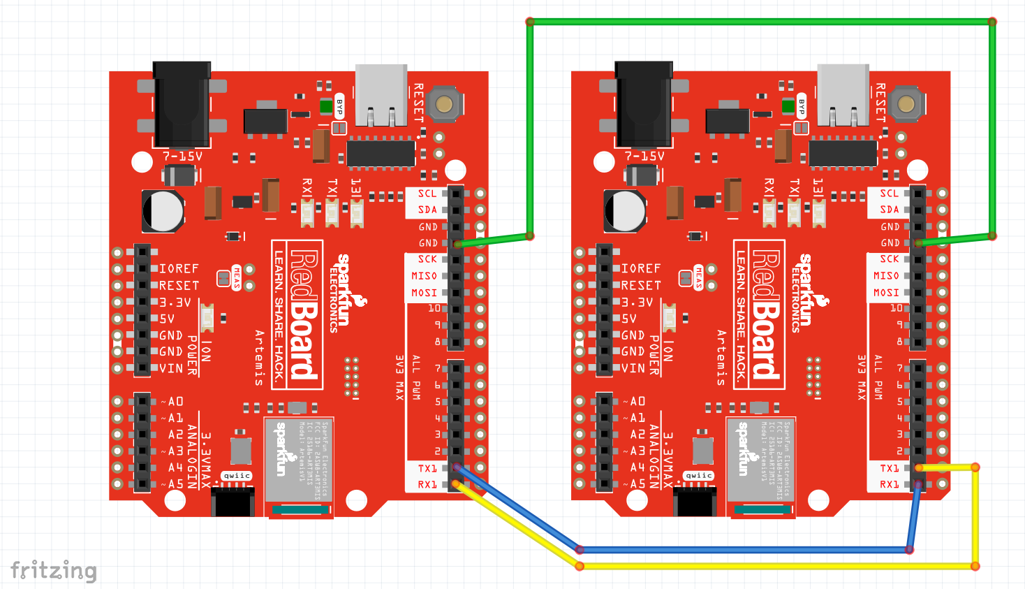
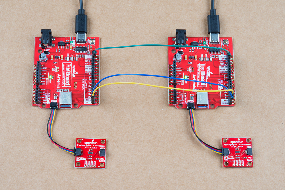
For Example 4, you will need to setup two Artemis boards with two co-processors, and connect a couple jumper wires between them. Using the Artemis Redboard, there is no soldering required for this setup.
Connect both of your Artemis boards to your computer using USB-C cables. Connect a Cryptographic Co-processor to each board using a Qwiic cable.
The board on the left is Alice. The board on the right is Bob. Connect Alice's TX1 pin to Bob's RX1 pin. Also connect GND to GND for good measure.
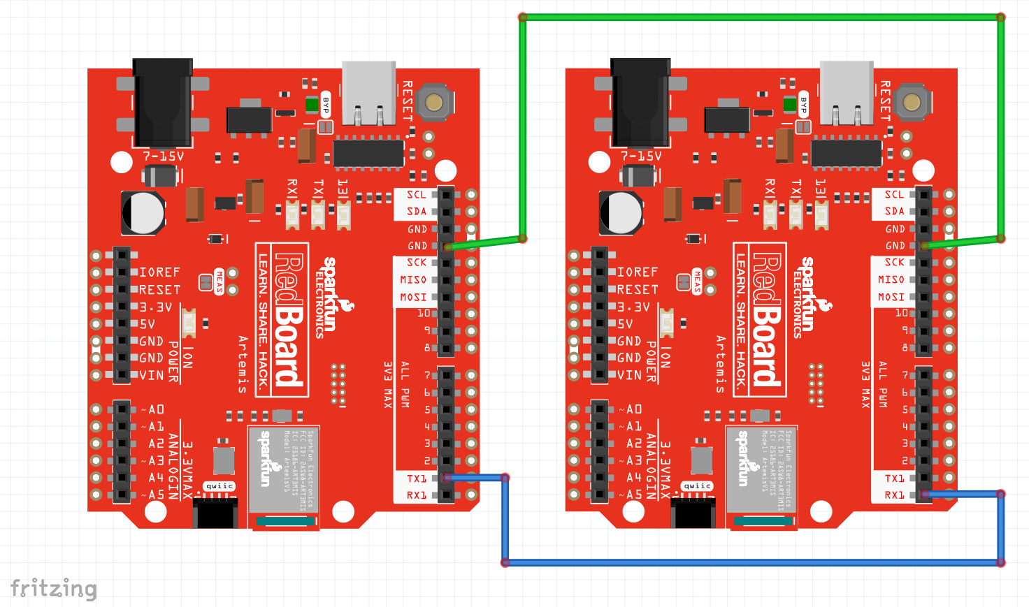
Note, both Alice and Bob need their own co-processor. So you're complete setup should look something like this:
Code setup
We will need to copy/paste Alice's public Key into the top of Bob's Sketch. First upload Alice's sketch to Alice, then watch her terminal at 115200. Copy her public key.
Now go over to Bob's sketch. Delete the place holder "blank" public key at the top, and paste in Alice's public key. Upload Bob's sketch to Bob.
Now watch both Alice's and Bob's terminal at 115200. Type a y into Alice's terminal, and she will send a signed message to Bob. Watch Bob's terminal. He will receive the message and verify it.
Watch this looped video to see it all happen. (click to enlarge).
Example4_Alice.ino and Example4_Bob.ino working in conjunction. (Click to Enlarge) Things to note about this:
We are now using two separate co-processors! In this example, Bob is simply using his co-processor as a verification engine. This could be accomplished by any computer that can compute ECC signature verification. But it's really quite nice to offload this calculation to a co-processor, and it will perform the calculations very fast.
Alice signed her message with her private key and she gave her public key to Bob. Hopefully the private vs public thing is starting to sink in.
Bob used an external public key (Alice's) to verify the authenticity of Alice. He could potentially name this anything he wants. And he could store lots of them, if he wanted to be able to verify messages from other senders.
Alice will most likely make her public key truly public and let everyone know about it. Once everyone has it, then she can send authenticated messages to anyone she likes, and they will truly know that it came from Alice.
It does not have to be a one-way street. The example could easily be reversed and Bob could give Alice his public key. When they both have shared their public key with the other, they can both send and verify.
The Code
As mentioned above, this example has two sketches. The purpose of splitting it up allows us to build upon the first three examples, and communicate securely between two completely separate systems.
Alice's sketch is actually quite similar to the Example2_Sign.ino, although it also sends the message and signature out it's TX1 pin.
Let's take a closer look at the important stuff within Alice's sketch:
language:c
//Let's create a digital signature!
atecc.createSignature(message); // by default, this uses the private key securely stored and locked in slot 0.

// Now let's send the message to Bob.
// this will include three things:
// (1) start header ("$$$") ASCII "$" = 0x24 HEX
// (2) message (32 bytes)
// (3) signature (64 bytes)

// start header
Serial1.print("$$$");

// message
// note, we use "Serial.write" because we are sending bytes of data (not characters)
for (int i = 0; i < sizeof(message) ; i++) Serial1.write(message[i]);

// signature
// Note, in Example4_Alice we are printing the signature we JUST created,
// and it lives inside the library as a public array called "atecc.signature"
for (int i = 0; i < sizeof(atecc.signature) ; i++) Serial1.write(atecc.signature[i]);
At the top of this code block, you can see she is using atecc.createSignature(message), just like in Example2_sign.
Then Alice sends everything to Bob, including a start "header" ($$$). This is simply used to avoid errors during transmission and helps ensure that Bob hears the entire message.
One important thing to note is that when Alice sends her message and signature to Bob, she uses the Serial1.write() function, because she is sending data (not ASCII characters).
Now let's take a closer look at the important stuff in Example4_Bob.ino. Bob's sketch is actually quite similar to Example3_Verify.ino, although he receives the message and signature on his RX1 pin.
language:c
// Delete this "blank" public key,
// copy/paste Alice's true unique public key from her terminal printout in Example4_Alice.

uint8_t AlicesPublicKey[64] = {
0xB4, 0x07, 0x88, 0x28, 0x8C, 0xFA, 0x71, 0xBA, 0x08, 0xE3, 0x38, 0xE0, 0x4A, 0x17, 0x68, 0xCC,
0x3E, 0xCD, 0x48, 0xA8, 0x11, 0x52, 0xDD, 0x37, 0xA1, 0xC2, 0x55, 0x75, 0x81, 0xBE, 0x4E, 0x7E,
0x78, 0x98, 0x95, 0xF6, 0x6D, 0xE7, 0x1C, 0x9A, 0x36, 0xE6, 0xB0, 0x14, 0x5D, 0x50, 0x67, 0x91,
0x7C, 0x41, 0xB8, 0x99, 0x20, 0x75, 0x3A, 0x7D, 0xA1, 0xFB, 0xF5, 0x5E, 0x8A, 0x65, 0xF5, 0x8A
};
At the top, you need to copy in Alice's public key. Bob will need this to verify any messages and signatures he receives. Note, yours will be different than what I'm showing above.
language:c
void loop()
{
  if (Serial1.available() > 0) // listen on Serial1
  {
    // check for start header
    byte input = Serial1.read();
    //Serial.print(input, HEX);
    if (input == '$') headerCount++;
    if (headerCount == 3)
    {
      delay(100); // wait for entire message to come into Serial1 buffer (96 bytes at 9600 baud).

      headerCount = 0; // reset
      Serial.println("Message Received!");
      Serial.println();

      for (int bytes = 0 ; bytes < 32 ; bytes++) message[bytes] = Serial1.read();

      for (int bytes = 0 ; bytes < 64 ; bytes++) signature[bytes] = Serial1.read();

      printMessage();

      printSignature();

      // Let's verirfy!
      if (atecc.verifySignature(message, signature, AlicesPublicKey)) Serial.println("Success! Signature Verified.");
      else Serial.println("Verification failure.");
    }
  }
}
Above, we have Bob's entire loop(). He is listening for incoming data on his RX1 pin. If he hears the expected $$$, then he starts reading in the message and the signature, storing them in variables for later use.
Then Bob uses the atecc.verifySignature() function to see if everything is authentic. Note his third argument to this function - he is using AlicesPublicKey!
Example 5: Random
This example shows how to use the Random Number Generator on the Sparkfun Cryptographic Co-processor. It will print random numbers once a second on the serial terminal at 115200.
This example only requires 1 Artemis and 1 co-processor. If you just completed example 4, you can choose to use Alice or Bob. This example helps set the stage for Example 6, so it's a good idea to check it out and see how the ATECC508A does random numbers - particularly its ability to create 32 bytes of random data!
Note, this chip is a bit more capable than the built-in Arduino function random().
random(max)random(min, max)
It has a basic random(min, max). This will return a random number of type long.
Note, it works very similarly to the built-in Arduino random() function, you can send it a single argument as a max, or you can send it two (as min and max).
It also has the following 3 other functions that can be useful in other applications.
getRandomByte()getRandomInt()getRandomLong()
Each of these functions return a random number of the type written into the name.
And lastly...
updateRandom32Bytes()will create 32 bytes of random data and store it inatecc.random32Bytes[].
After calling updateRandom32Bytes() then your random 32 bytes of data are available at a public variable
within the library instance. If your instance was named atecc as in the SparkFun examples,
this array would be atecc.random32Bytes[]. This can be useful as a challenge or time-to-live-token (aka NONCE) to send to another device.
Example 6: Challenge
This example shows how to setup a "challenge and response" for authentication between two systems. This is one way to add more security to your communication channel. More specifically, it prevents attackers from intercepting a message and sending it at a later time. This doesn't seem like such a bad thing, but timing of a message is sometimes equally as important as the message itself. Once such interception attack was called the RollJam, and could be used to maliciously open garage doors and unlock cars. After completing this example, you will be able to defend your projects against this type of attack!
Hardware Hookup
For Example6_Challenge, you will need to setup two Artemis boards (each with their own co-processors) and connect a few jumper wires between Alice and Bob.
Connect the following pins like so:
| Alice (left) | Bob (right) |
|---|---|
| GND | GND |
| TX1 | RX1 |
| RX1 | TX1 |
Note, you're setup will also need to include a co-processor on each side connected via qwiic cables, and should look something like this:
Code Setup
Like Example 4, this also requires two unique sketches and setups. You will need to use both Example6_Challenge_Alice.ino and Example6_Challenge_Bob.ino.
Again, you will need to copy Alice's public key from her serial terminal, and then paste it into the top of Bob's sketch. Then upload Bob's sketch and watch both terminals.
Example6_Challenge_Alice.ino and Example6_Challenge_Bob.ino working in conjunction. For any new authentication cycle, Alice will initiate. User must reset Alice and send a "y" over serial at 115200.
Bob will create a new random array of 32 bytes (this will be called a token - aka NONCE).
It is also known as a "time-to-live token", because it will become invalid after a set amount of time.
Bob sends the token to Alice.
Alice will sign the token using her private ECC key, then send the signature to Bob.
Bob will use the token, the signature, and Alice's Public Key to verify everything.
By creating a new random token, Bob now has the ability to control how long he thinks that token should be valid. This means that if an attacker intercepted the message, and they tried to send it later, it would no longer be valid.
Bob will also invalidate the token after a set amount of time. For our example it will be 150ms. This prevents any attacker from intercepting the message, and hanging on to it for later use. So if Alice doesn't respond within the set window of time (150ms), then Bob will clear out the token, and Alice must ask for another.
Because the token is unique every time, that means that Alice's signature will be unique every time. This prevents an attacker from trying to impersonate Alice by recording communications, and then later sending one.
Troubleshooting
Need help?
If your product is not working as you expected or you need technical assistance or information, head on over to the SparkFun Technical Assistance page for some initial troubleshooting.
If you don't find what you need there, the SparkFun Forums are a great place to find and ask for help. If this is your first visit, you'll need to create a Forum Account to search product forums and post questions.
For extra guidance, checkout the product video, which also includes the examples, laid out in this tutorial.
Resources and Going Further
Now that you've sent signed message between two systems, you are ready to integrate some security into your projects! In these examples we have used hard-wired serial messages between two Arduinos. That communication channel could be anything: Bluetooth, RFM69s, Wifi and the internet, you name it! Good luck!
- Schematic (PDF)
- Eagle Files (ZIP)
- Github (Hardware)
- Github (Arduino Library)
- Microchip ATECC508A DataSheet (PDF)
- CryptoAuthLib - Microchip CryptoAuthentication Library (includes python support)
- Board Dimensions (PDF) or (PNG)
- Product Video
Additional Documentation on the Cryptographic Standards (linked from datasheet):
- SHA-256 Algorithm
- HMAC Algorithm
- Elliptic Curve Digital Signature Algorithm (ECDSA)
- Elliptic Curve Diffie-Hellman (ECDH) Key Agreement (Revision 2)
- Elliptic Curve Diffie-Hellman (ECDH) Key Agreement (Revision 2- Draft)
- Diversified Keys
- NIST CAVP certification of the RNG
Need inspiration? Check out some of the Qwiic or IoT related tutorials!