Qwiic Differential I2C Bus Extender (PCA9615) Hookup Guide
 Joel_E_B,
  Alex the Giant
 Introduction
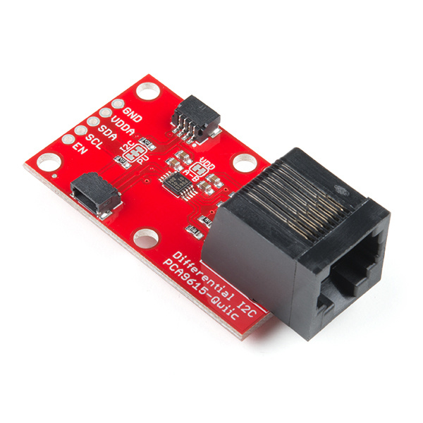
The Qwiic Differential I2C Breakout is the fastest and easiest way to extend the range of your I2C communication bus. The breakout uses NXP's PCA9615 IC, which converts the two default I2C signals into four differential signals: two for SCL and two for SDA. Coupled with the ease of SparkFun's Qwiic connection system, the differential I2C breakout board makes it easier to connect it to the rest of your system. The differential signals are sent over an Ethernet cable, which attaches to the breakouts through the on-board RJ-45 connectors. The differential signaling allows the I2C signals to reach distances of up to 100ft. while still maintaining their signal integrity!
Whether you need to extend the range of an I2C sensor on an autonomous vehicle plagued with noise from motors or want to create a vast sensor network in your home or office, the Qwiic differential I2C breakout is a great solution to extend distance and reduce noise susceptibility.
Required Materials
To follow along with this project tutorial, you will need the following materials. You may not need everything though depending on what you have. Add it to your cart, read through the guide, and adjust the cart as necessary.
- 2x Qwiic Differential I2C breakouts.
- A straight-through Ethernet cable (up to 100ft in length).
- A microcontroller or single board computer capable of I2C.
- An I2C sensor to communicate with on the other end of the I2C bus.
- If using the Qwiic connectors, two Qwiic cables.
Tools
You may need a soldering iron, solder, general soldering accessories, and a hobby knife depending on your setup.


Weller WLC100 Soldering Station
TOL-14228Suggested Reading
If you aren't familiar with the Qwiic system, we recommend reading here for an overview.
| Qwiic Connect System |
We would also recommend taking a look at the following tutorials if you aren't familiar with them.
Logic Levels
I2C
How to Work with Jumper Pads and PCB Traces
Qwiic Shield for Arduino & Photon Hookup Guide
Qwiic HAT for Raspberry Pi Hookup Guide
Hardware Overview
The simplicity of the Qwiic differential I2C breakout is one of its biggest appeals. Other I2C communication methods require packetizing I2C communication into another protocol, be it RS-485 or 1-Wire. However, the PCA9615 keeps the I2C protocol by utilizing a differential transceiver. In this section, we'll take a closer look at the board to better understand how it works.
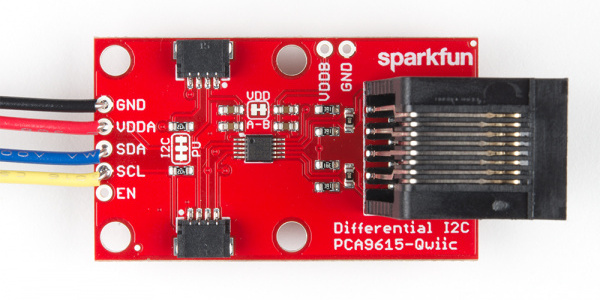
Pinout
Below are the plated through hole pins that are broken out on the board. The I2C pins are connected to the two Qwiic connectors on the sides.
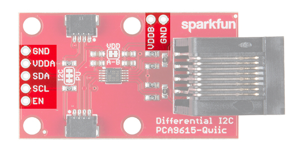
PTH Connections
- GND - Ground
- VDDA - 2.3VDC to 5.5VDC. I2C-bus side power supply.
- VDDB - 3.0VDC to 5.5VDC. Differential side power supply. If jumper "VDD A-B" is not shorted, then VDDB will need to be powered for the differential I2C bus to operate.
- SDA - I2C data signal.
- SCL - I2C clock signal.
- EN (optional) - PCA9615 enable (active high, internally pulled up). This is used to disable the bus buffer, and is useful for fault finding, power-up sequencing, or reconfiguration of a large bus system by isolating sections not needed at all times.
Qwiic Connections
- GND - Ground.
- VDDA - 2.3VDC to 5.5VDC. I2C-bus side power supply. If "VDD A-B" is not shorted, VDDB will need to powered separately for the differential I2C bus to operate.
- SDA - I2C data signal.
- SCL - I2C clock signal.
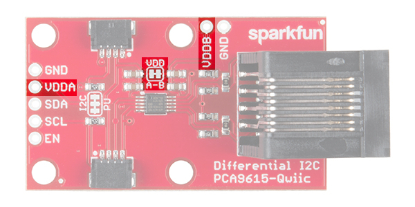
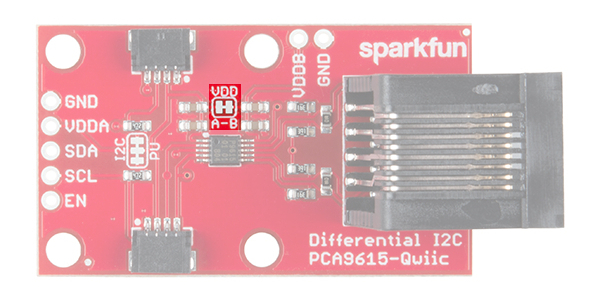
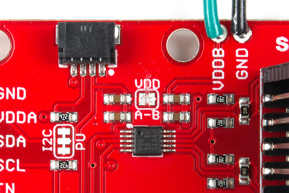
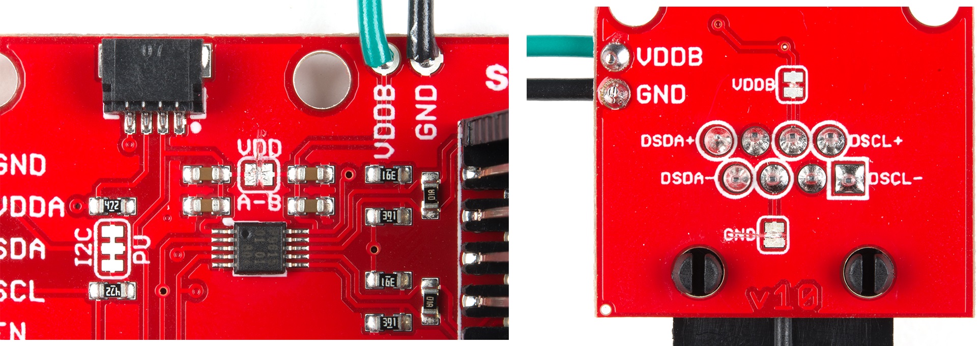
VDDA vs VDDB
To power the board, VDDA must be present and be the same logic voltage as the SDA/SCL lines, while VDDB is used to power the differential I2C bus. By default, the jumper labeled "VDD A-B" is closed, which connects the VDDA rail to the VDDB rail. By cutting the jumper you can separate the two rails which would allow for one rail to operate at 3.3V while the other can operate at 5V.
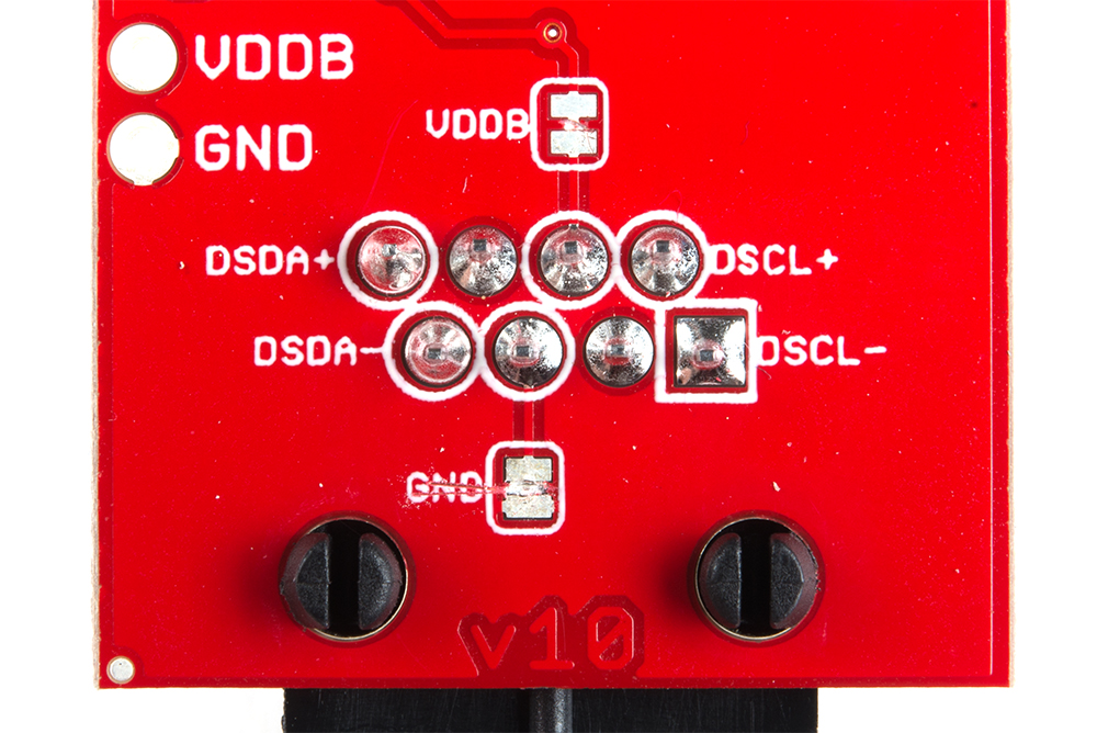
VDDB and Ground Jumpers
If the number of sensors connected on the other side of the extended I2C bus is minimal, you can power them over the Ethernet cable. However, if there are numerous sensors connected, it is advised that both ends be powered separately. To isolate the power supplies at both ends of the Ethernet cable, use a sharp blade to cut the small traces betweens the pads of the jumpers labeled "VDDB" and "GND". VDDB will still be present on each board, but the Ethernet cable will not carry any current to power a device at the other end of the cable.
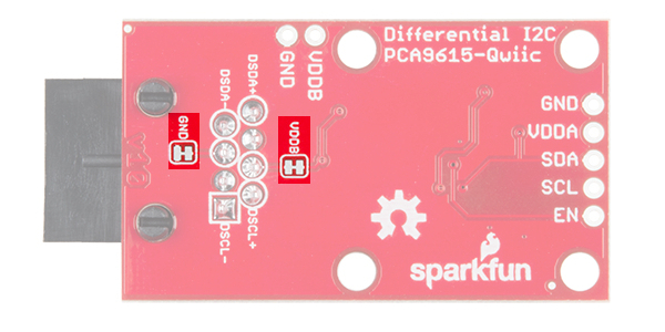
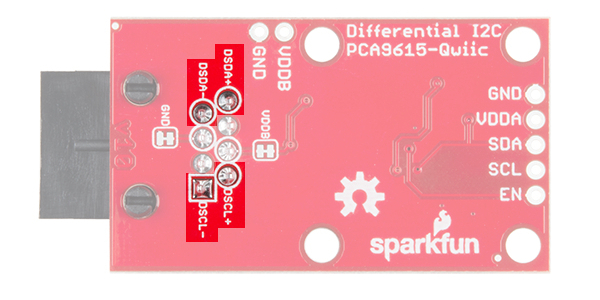
Differential Signals
From the bottom of the board, we can see which pins the RJ-45 connector uses for the differential signaling. The board has been designed to use a standard Ethernet cable. If a custom cable is made, make sure to connect a twisted pair for pins 1 and 2 (DSCL-, DSCL+) and pins 7 and 8 (DSDA-, DSDA+).
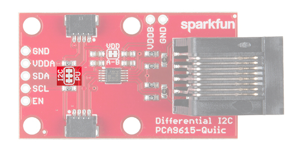
I2C Pull-Up Resistors
As with most SparkFun I2C products, there is a jumper for the pull-up resistors on the I2C bus. If multiple sensors are connected to the bus with the pull-up resistors enabled, the parallel equivalent resistance will create too strong of a pull-up for the bus to operate correctly. As a general rule of thumb, disable all but one pair of pull-up resistors if multiple devices are connected to the bus.
Hardware Assembly
Ethernet cables used must be straight-through (i.e. Pin 1 on one side of the cable is connect to pin 1 on the other side. The same for pin 2 and so on.).
I2C Pull-Up Resistors
Remember, each individual non-differential I2C bus needs at least one set of pull-up resistors enabled. Make sure you keep track of which devices have their I2C pull-ups enabled and which do not.
Power Schemes
With two power supply rails and quite a few jumpers, it's easy to feel confused about how to power the differential I2C bus extender. In this section, we'll go over the different ways you can power your project.
VDD_A == VDD, Power Whole Bus (Default)
- VDD_A and VDD_B are connected.
- Both are powered at 3.3V.
- Power is connected to a twisted pair of the Ethernet cable and sent to the peripheral nodes.
- No power is required at the peripheral nodes.
VDD_A != VDD_B, Power Whole Bus
- VDD A-B jumper trace has been cut.
- Separate power supply (3.0-5.5V) is supplied to VDD_B, while VDD_A remains at 3.3V.
- VDD_B voltage is connected to a twisted pair of the Ethernet cable and sent to the peripheral nodes.
- No power is required at the peripheral nodes.
VDD_A == VDD_ B, Power Each Node Separately
- VDD_A and VDD_B are connected.
- Both are powered at 3.3V.
- Jumpers underneath board (VDDB and GND) are cut and power is NOT connected to the Ethernet cable.
- Each peripheral node is powered individually with 3.3V only. Differential I2C signals are the only connections on the bus.
VDD_A != VDD_ B, Power Each Node Separately
- VDD A-B jumper trace has been cut on the top of the board.
- Separate power supply (3.0-5.5V) is supplied to VDD_B, while VDD_A remains at 3.3V.
- Jumpers underneath board (VDDB and GND) are cut and power is NOT connected to the Ethernet cable.
- Each peripheral node is powered individually with 3.3V only. Differential I2C signals are the only connections on the bus.
VDD_A == VDD_ B, Power Whole Bus (Non-Qwiic Option)
- VDD_A and VDD_B are connected.
- Both are powered at 5V.
- Power is connected to a twisted pair of the Ethernet cable and sent to the peripheral nodes.
- No power is required at the peripheral nodes.
VDD_A == VDD_ B, Power Each Node Separately (Non-Qwiic Option)
- VDD_A and VDD_B are connected.
- Both are powered at 5V.
- Jumpers underneath board (VDDB and GND) are cut and power is NOT connected to the Ethernet cable.
- Each peripheral node is powered individually with 5V only. Differential I2C signals are the only connections on the bus.
I2C Bus Extender Example
For this example, we're going to use our Environmental Combo Breakout using the Differential I2C Bus Extender. To follow along in this example, you'll need the following:
You'll also need a straight-through Ethernet cable (up to 100ft).
Hardware Hookup
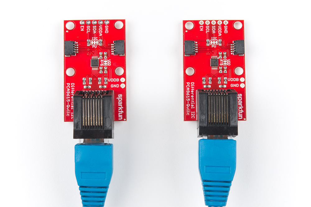
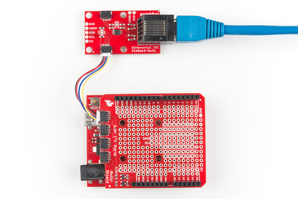
You'll first need to solder the headers on to the Qwiic shield and then connect the shield to the Redboard. Once that's done, you can connect one of the differential I2C to your Redboard as shown below using one of the Qwiic cables.
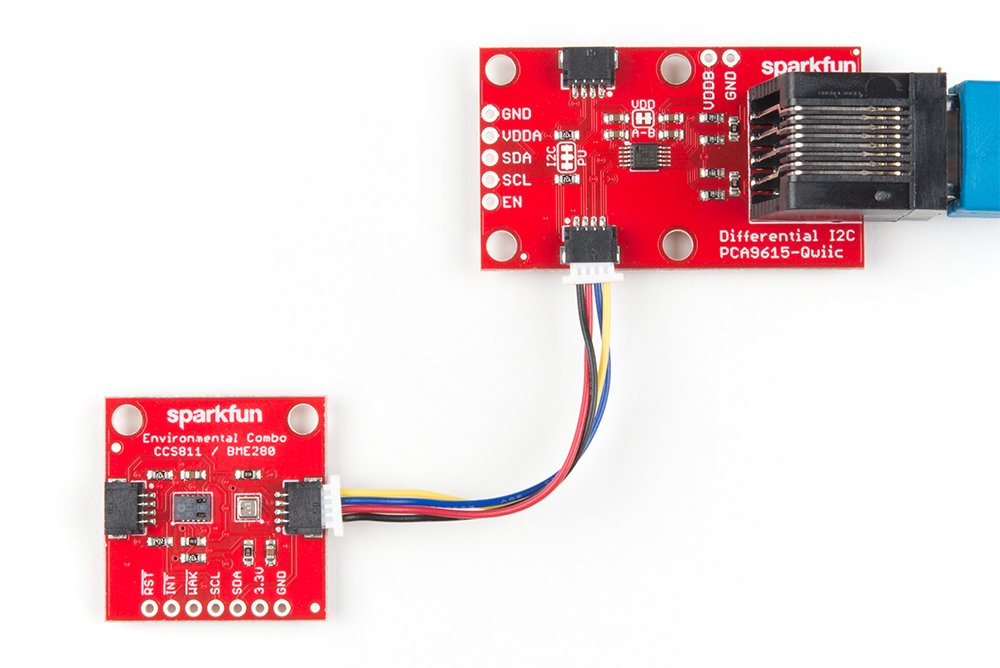
On the other end, all that's needed is to connect the environmental combo sensor to the other differential I2C using another Qwiic cable as shown below.
Arduino Library Installation
Note: This example assumes you are using the latest version of the Arduino IDE on your desktop. If this is your first time using Arduino, please review our tutorial on installing the Arduino IDE. If you have not previously installed an Arduino library, please check out our installation guide.
We're going to use the code from the environmental combo sensor's hookup guide.
CCS811/BME280 (Qwiic) Environmental Combo Breakout Hookup Guide
Since we are using the environmental combo sensor, the BME280 and CCS811 libraries need to be installed. SparkFun has written libraries to control both the CCS811 and the BME280. You can obtain these libraries through the Arduino Library Manager. Search for SparkFun BME280 and SparkFun CCS811 to install the latest version. If you prefer downloading the libraries, you can grab them here to manually install:
Example Code
With the sensor connected via the I2C bus extender, we will use example 2 of the environmental combo breakout. Assuming that you have installed the library for both sensors, copy the code below and paste it into your Arduino IDE and upload the sketch to your board.
language:c
#include <SparkFunBME280.h>  //https://github.com/sparkfun/SparkFun_BME280_Arduino_Library/
#include <SparkFunCCS811.h>  //https://github.com/sparkfun/SparkFun_CCS811_Arduino_Library/

#define CCS811_ADDR 0x5B //Default I2C Address
//#define CCS811_ADDR 0x5A //Alternate I2C Address

//Global sensor objects
CCS811 myCCS811(CCS811_ADDR);
BME280 myBME280;

void printData()
{
  Serial.print(" CO2[");
  Serial.print(myCCS811.getCO2());
  Serial.print("]ppm");

  Serial.print(" TVOC[");
  Serial.print(myCCS811.getTVOC());
  Serial.print("]ppb");

  Serial.print(" temp[");
  Serial.print(myBME280.readTempC(), 1);
  Serial.print("]C");

  //Serial.print(" temp[");
  //Serial.print(myBME280.readTempF(), 1);
  //Serial.print("]F");

  Serial.print(" pressure[");
  Serial.print(myBME280.readFloatPressure(), 2);
  Serial.print("]Pa");

  //Serial.print(" pressure[");
  //Serial.print((myBME280.readFloatPressure() * 0.0002953), 2);
  //Serial.print("]InHg");

  //Serial.print("altitude[");
  //Serial.print(myBME280.readFloatAltitudeMeters(), 2);
  //Serial.print("]m");

  //Serial.print("altitude[");
  //Serial.print(myBME280.readFloatAltitudeFeet(), 2);
  //Serial.print("]ft");

  Serial.print(" humidity[");
  Serial.print(myBME280.readFloatHumidity(), 0);
  Serial.print("]%");

  Serial.println();
}

void printDriverError( CCS811Core::status errorCode )
{
  switch ( errorCode )
  {
    case CCS811Core::SENSOR_SUCCESS:
      Serial.print("SUCCESS");
      break;
    case CCS811Core::SENSOR_ID_ERROR:
      Serial.print("ID_ERROR");
      break;
    case CCS811Core::SENSOR_I2C_ERROR:
      Serial.print("I2C_ERROR");
      break;
    case CCS811Core::SENSOR_INTERNAL_ERROR:
      Serial.print("INTERNAL_ERROR");
      break;
    case CCS811Core::SENSOR_GENERIC_ERROR:
      Serial.print("GENERIC_ERROR");
      break;
    default:
      Serial.print("Unspecified error.");
  }
}

void setup()
{
  Serial.begin(9600);
  Serial.println();
  Serial.println("Apply BME280 data to CCS811 for compensation.");

  //This begins the CCS811 sensor and prints error status of .begin()
  CCS811Core::status returnCode = myCCS811.begin();
  if (returnCode != CCS811Core::SENSOR_SUCCESS)
  {
    Serial.println("Problem with CCS811");
    printDriverError(returnCode);
  }
  else
  {
    Serial.println("CCS811 online");
  }

  //Initialize BME280
  //For I2C, enable the following and disable the SPI section
  myBME280.settings.commInterface = I2C_MODE;
  myBME280.settings.I2CAddress = 0x77;
  myBME280.settings.runMode = 3; //Normal mode
  myBME280.settings.tStandby = 0;
  myBME280.settings.filter = 4;
  myBME280.settings.tempOverSample = 5;
  myBME280.settings.pressOverSample = 5;
  myBME280.settings.humidOverSample = 5;

  //Calling .begin() causes the settings to be loaded
  delay(10);  //Make sure sensor had enough time to turn on. BME280 requires 2ms to start up.
  byte id = myBME280.begin(); //Returns ID of 0x60 if successful
  if (id != 0x60)
  {
    Serial.println("Problem with BME280");
  }
  else
  {
    Serial.println("BME280 online");
  }
}

void loop()
{
  if (myCCS811.dataAvailable()) //Check to see if CCS811 has new data (it's the slowest sensor)
  {
    myCCS811.readAlgorithmResults(); //Read latest from CCS811 and update tVOC and CO2 variables
    //getWeather(); //Get latest humidity/pressure/temp data from BME280
    printData(); //Pretty print all the data
  }
  else if (myCCS811.checkForStatusError()) //Check to see if CCS811 has thrown an error
  {
    Serial.println(myCCS811.getErrorRegister()); //Prints whatever CSS811 error flags are detected
  }

  delay(2000); //Wait for next reading
}
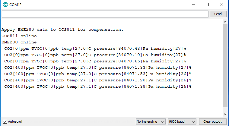
Once uploaded, open your favorite serial monitor to the port assigned to the Arduino. You should see something like similar to the output below:
Resources and Going Further
Now that you've successfully got your differential I2C breakout up and running, it's time to incorporate it into your own project!
For more on the differential I²C breakout, check out the links below:
- Schematic (PDF)
- Eagle Files (ZIP)
- PCA9615 Datasheet (PDF)
- Qwiic Landing Page
- GitHub Repo
- SFE Product Showcase: Differential I2C Breakout
For more information related to I²C over long distances, check out the resources below:
- An Introduction to I²C Over Long Wires
- An Introduction to Differential I²C
- Differential I²C Application Note - AN10710 (PDF)
- One mile long I²C communication (PDF)
Need some inspiration for your next project? Check out some of these related tutorials: