Qwiic MUX Hookup Guide
 Englandsaurus
 Introduction
The Qwiic Mux - TCA9548A (v1) and (v1.1) enable communication with multiple I2C devices that have the same address. The IC is simple to interface with and also has 8 configurable addresses of its own, this allows you to put 64 I2C buses on a single bus!
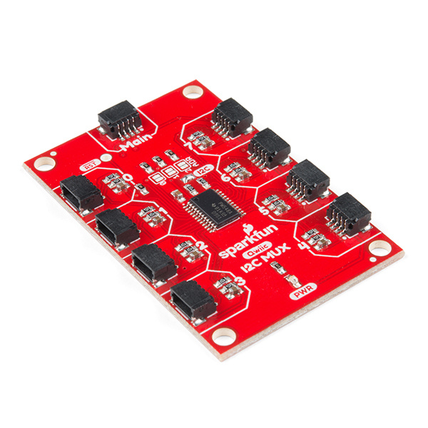
Revision Update: In the latest revision of the Qwiic MUX, we have made a few changes to improve the board, listed below. If users are unsure about which version they purchased, please refer to the pictures of the most prominent changes, shown below.
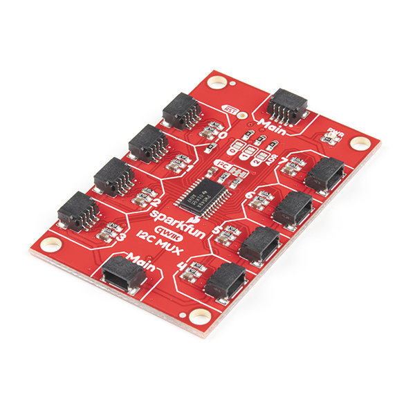
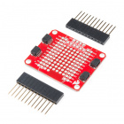
- We have added a pass-through Qwiic connector.
- The power LED was moved to accommodate the additional Qwiic connector.
- We have updated the I2C pull-up resistor jumper to a cuttable trace.
- We have widened the trace for the 3.3V power.
- There is a v11 label on the back of the board.
- The silk screen labels have been updated.
Added Qwiic connector to make board daisy-chainable.
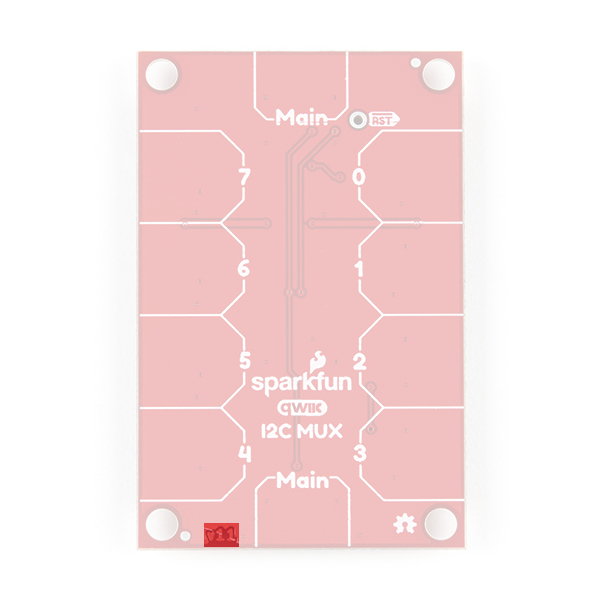
The v11 label on the back.
In this tutorial we'll go over how to talk to sensors on different channels of your MUX breakout board. The application of this is pretty straightforward so things won't get too fancy.
Required Materials
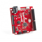
You'll need a few additional items to get started with the Qwiic Mux. The RedBoard Qwiic is for the Arduino examples and the Qwiic pHAT is for the Raspberry Pi example (see note below). You may already have a few of these items, so feel free to modify your cart based on your needs. Additionally, there are also alternative parts options that are available as well (click button below to toggle options).


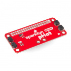
SparkFun Qwiic pHAT for Raspberry Pi
DEV-15351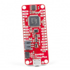
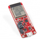
SparkFun Thing Plus - ESP32 WROOM
WRL-14689

SparkFun Qwiic Shield for Photon
DEV-14477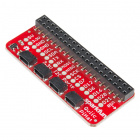
SparkFun Qwiic pHAT for Raspberry Pi
DEV-15351
Qwiic Cable - 50mm
PRT-14426
Qwiic Cable - 100mm
PRT-14427
Qwiic Cable - 200mm
PRT-14428
Qwiic Cable - 500mm
PRT-14429Raspberry Pi Example: If you don't already have them, you will need a Raspberry Pi and standard peripherals. An example setup is listed below. (The Qwiic Mux and Python library have not been tested on the newly released Raspberry Pi 4 because we don't carry it in out catalog yet.)
Update: This board and the Python package have been verified to work with the Raspberry Pi 4.
Tools
Depending on your setup, you may need a hobby knife, soldering iron, solder, and/or general soldering accessories.


Weller WLC100 Soldering Station
TOL-14228
Slice Craft Knife
TOL-14508Suggested Reading
If you're unfamiliar with jumper pads, I2C, Qwiic, or Python be sure to checkout some of these foundational tutorials.
Serial Communication
Logic Levels
I2C
Serial Terminal Basics
Raspberry Pi SPI and I2C Tutorial
Raspberry Pi 3 Starter Kit Hookup Guide
Python Programming Tutorial: Getting Started with the Raspberry Pi
Qwiic pHAT for Raspberry Pi Hookup Guide
How to Work with Jumper Pads and PCB Traces
Qwiic Shield for Arduino & Photon Hookup Guide
RedBoard Qwiic Hookup Guide
The Qwiic Mux is intended for the Qwiic connect system. We recommend familiarizing yourself with the Logic Levels and I2C tutorials before using it. Click on the banner above to learn more about our Qwiic products.
Hardware Overview
Let's look over a few characteristics of the TCA9548A so we know a bit more about how it behaves.
| Characteristic | Range |
|---|---|
| Operating Voltage | 1.65V - 5.5V |
| Operating Temperature | -40 - 85° C |
| I2C Address | 0x70 (default) up to 0x77 (see below table) |
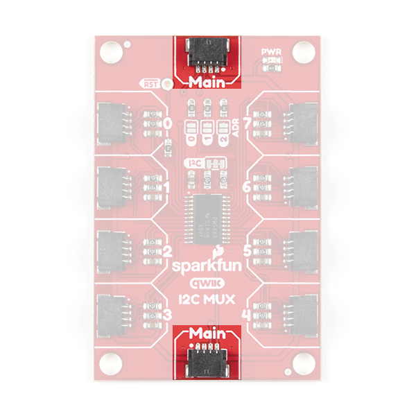
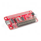
Original Release:The Qwiic input for the Mux is located at the top-center of the board, labeled Main, highlighted in the image below. The outputs are then located on the left and right sides of the board and are numbered accordingly.
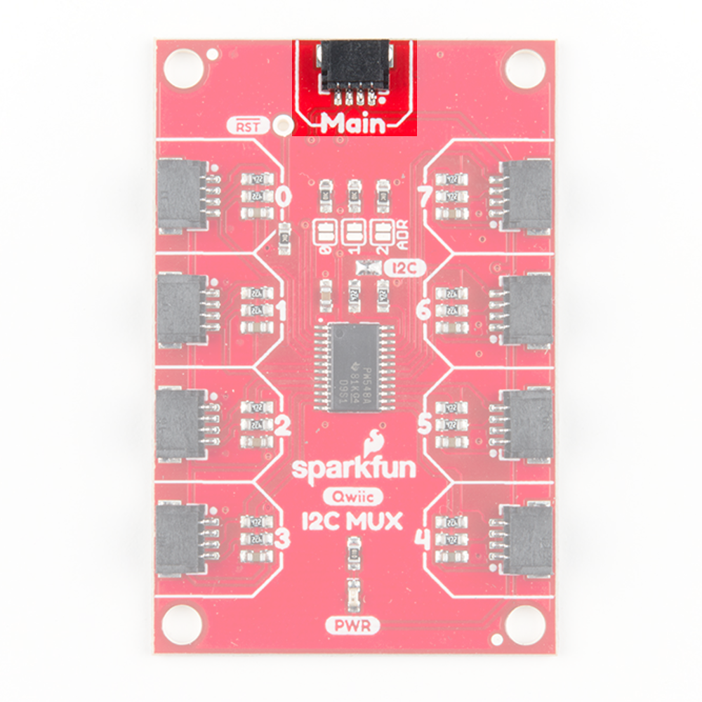
Revision Update: There are two Main connectors on the revision to provide a pass through for the I2C bus connection. This allow the board to be daisy chained in between other Qwiic boards.
The onboard reset pin, highlighted below, is an active low input. Pulling reset low for at least 6 ns will restart the multiplexer.

The Qwiic Mux also allows you to change the last 3 bits of the address byte, allowing for 8 jumper selectable addresses if you happen to need to put more than one Mux on the same I2C port. The address can be changed by adding solder to any of the three ADR jumpers, shown in the image below.
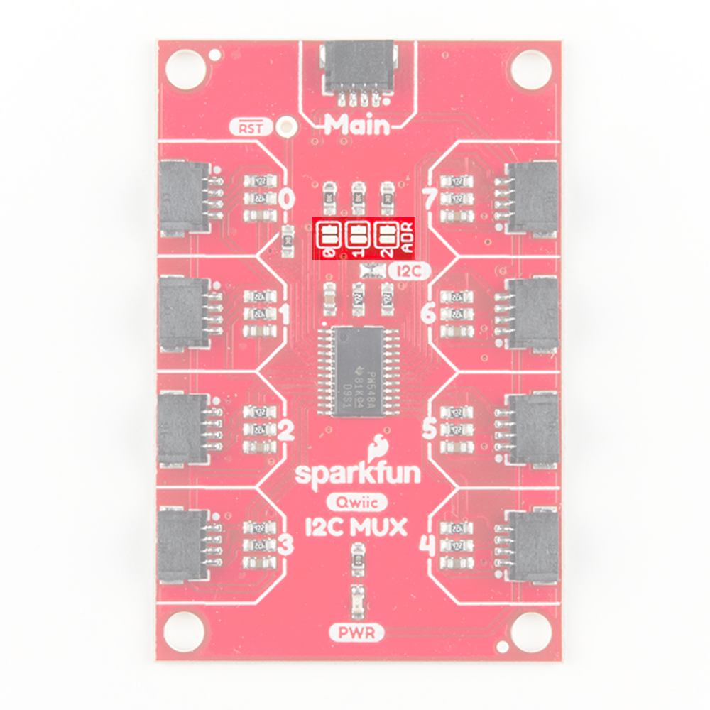
The below table shows which jumpers must be soldered together to change to the corresponding address.
| I2C Address | ADR2 | ADR1 | ADR0 |
|---|---|---|---|
| 0x70 | Open | Open | Open |
| 0x71 | Open | Open | Closed |
| 0x72 | Open | Closed | Open |
| 0x73 | Open | Closed | Closed |
| 0x74 | Closed | Open | Open |
| 0x75 | Closed | Open | Closed |
| 0x76 | Closed | Closed | Open |
| 0x77 | Closed | Closed | Closed |
Original Release:If you want to remove the pullup resistors from the I2C bus, simply remove the solder from the jumper highlighted in the below image.
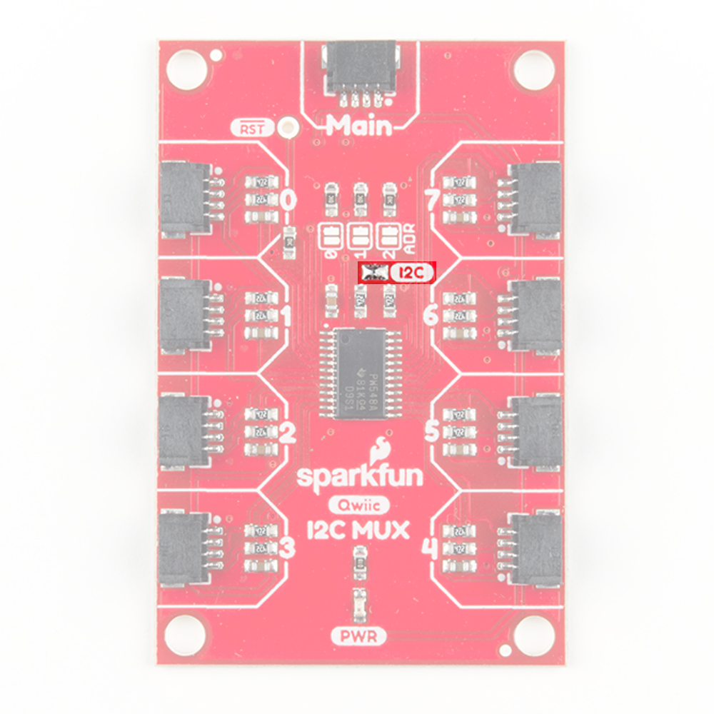
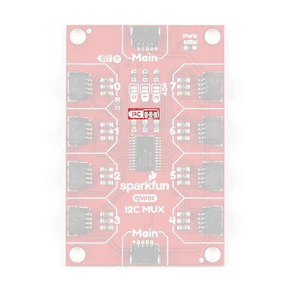
Revision Update: If you want to remove the pullup resistors from the I2C bus, simply cut the jumper pad with a hobby knife. Be careful of the 3.3V trace above the jumper pad. Cutting the trace probably won't destroy the board, as the trace also circles around through the Qwiic connector on the bottom. However, it will leave the trace exposed at the cut.
Hardware Assembly
Arduino Example
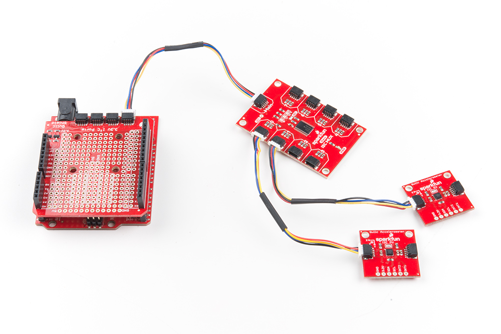
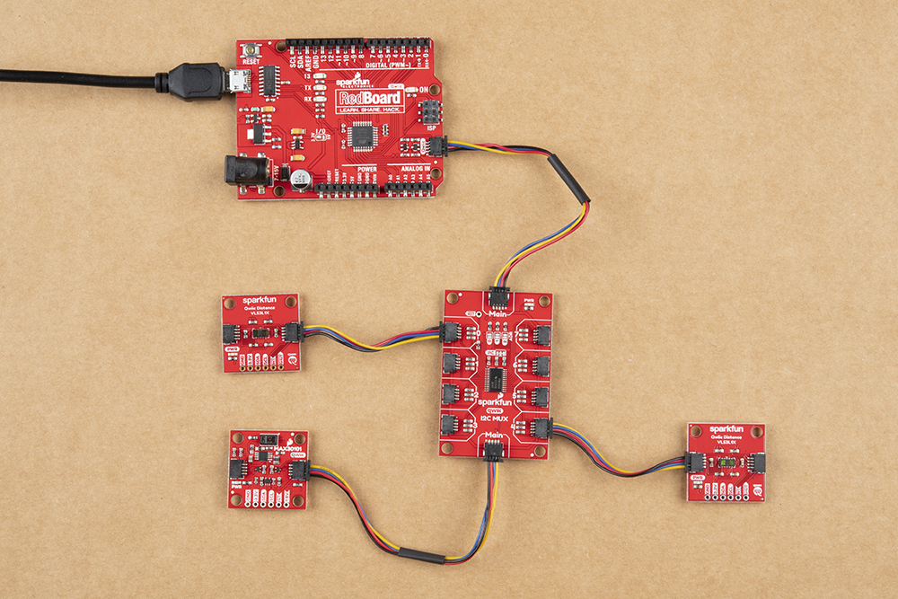
Just plug one end of the Qwiic cable into the Main connector on the Qwiic multiplexer breakout and the other end into Qwiic connector on your Qwiic enabled microcontroller. If it seems like it's too easy to use, but that's why we made it that way! Otherwise, if you chose to use a Qwiic shield/adapter, now would be the time to head on over to that tutorial to assemble the shield.
With the shield assembled, SparkFun's new Qwiic environment means that connecting the mux could not be easier. Just plug one end of the Qwiic cable into the Qwiic multiplexer breakout (Main connector) and the other into the Qwiic Shield; then, you'll be ready to upload a sketch and figure out just how all those address sharing sensors are behaving.
Revision Update: Users can now daisy chain the Qwiic Mux in between other Qwiic boards.
Raspberry Pi Examples
Note: This board and the Python package have not been tested on the newly released Raspberry Pi 4 because we don't carry it in out catalog yet.
Update: This board and the Python package have been verified to work with the Raspberry Pi 4.
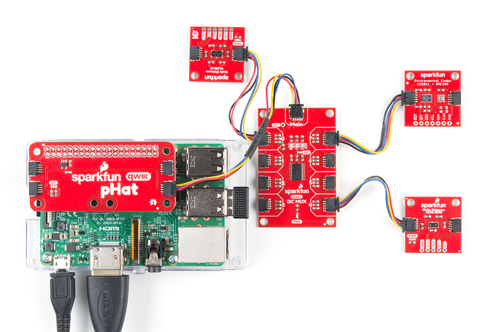
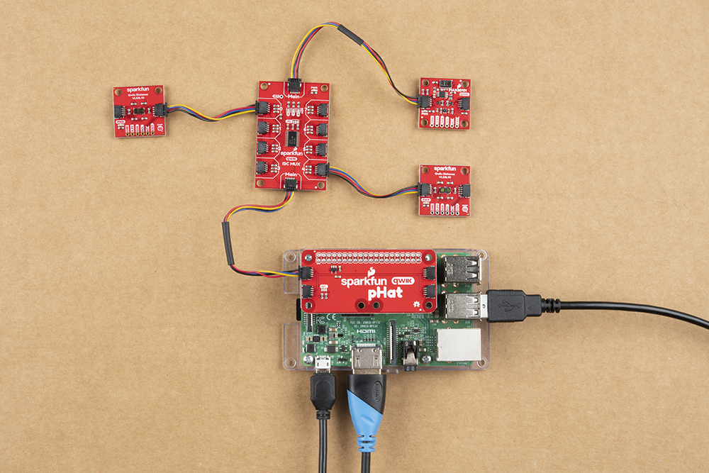
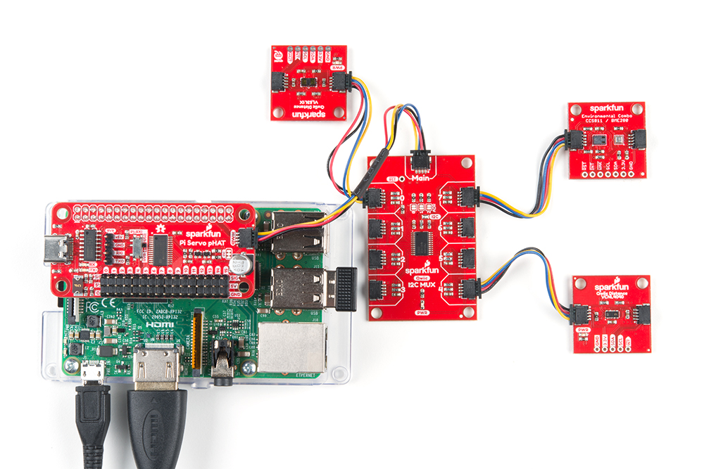
With the Qwiic connector system, assembling the hardware is simple. In addition to the Qwiic Mux, you will need: a Qwiic cables, a SparkFun Qwiic pHAT for Raspberry Pi, and a Raspberry Pi setup with the Raspbian OS, monitor, and standard peripherals. (*If you are unfamiliar with the Qwiic pHAT, you can find the Hookup Guide here.)
Revision Update: Users can now daisy chain the Qwiic Mux in between other Qwiic boards.
Alternatively, you can also use another Qwiic adapter like the Pi Servo pHat instead.
Note: This tutorial assumes you are familiar with using a Raspberry Pi and you have the latest (full... with recommended software) version of Raspbian OS your Raspberry Pi. You can download the latest version of the Raspbian OS from the Raspberry Pi Foundation website. As of Feb. 13th 2019, we recommend the Raspbian Stretch with desktop and recommended software option.
If this is your first time using a Raspberry Pi, please head over to the Raspberry Pi Foundation website to use their quickstart guides. We have listed a few of them here:
Arduino Example
Note: This tutorial assumes you are familiar with Arduino products and you are using the latest stable version of the Arduino IDE on your desktop. If this is your first time using the Arduino IDE, please review our tutorial on installing the Arduino IDE.
SparkFun has written some example code to enable and disable ports on the Qwiic Mux. Go ahead and download this example code here.
Additionally, you will need to install the MMA8452Q Arduino library if you are using two MMA8452Q accelerometers. First, you’ll need the Sparkfun MMA8452Q Arduino library. You can obtain these libraries through the Arduino Library Manager. Search for Sparkfun MMA8452Q Accelerometer by SparkFun Electronics to install the latest version. If you prefer downloading the libraries from the GitHub repository and manually installing it, you can grab them here:
Arduino Example Example1-BasicReadings.ino
Opening Example1-BasicReadings will open two tabs in the Arduino IDE, the first example, and also Mux_Control. Let's take a look under the hood of Mux_Control to get an idea of what's going on. There are two functions here, boolean enableMuxPort(byte portNumber) and boolean disableMuxPort(byte portNumber) which is pretty much all we need to specify which channels we'd like to talk to on the Mux. If we have a sensor on channel 0, we simply call enableMuxPort(0) to open that channel on the multiplexer. Then we'll take whatever reads and perform whatever actions we'd like to the sensor on that channel. Once finished, we have to call disableMuxPort(0) to close communication on that channel so we don't accidentally perform actions on the sensor on that channel. The below example code shows how to read from two MMA8452Q accelerometers.
language:c
#include <Wire.h>
#include <SparkFun_MMA8452Q.h> //From: https://github.com/sparkfun/SparkFun_MMA8452Q_Arduino_Library

#define NUMBER_OF_SENSORS 2

MMA8452Q accel[NUMBER_OF_SENSORS]; //Create an array of MMA8452Q sensors

void setup()
{
  Serial.begin(115200);
  Serial.println("Qwiic Mux Shield Read Example");
  Wire.begin();

  //Disable all eight mux ports initially, then we can enable them one at a time
  for (byte x = 0 ; x <= 7 ; x++)
  {
    disableMuxPort(x);
  }

  //Initialize all the sensors
  for (byte x = 0 ; x < NUMBER_OF_SENSORS ; x++)
  {
    enableMuxPort(x); //Tell mux to connect to port X
    accel[x].init(); //Init the sensor connected to this port
    disableMuxPort(x);
  }

  Serial.println("Mux Shield online");
}

void loop()
{
  for (byte x = 0 ; x < NUMBER_OF_SENSORS ; x++)
  {
    enableMuxPort(x); //Tell mux to connect to this port, and this port only

    if (accel[x].available())
    {
      accel[x].read();

      Serial.print("Accel ");
      Serial.print(x);
      Serial.print(": ");
      Serial.print(accel[x].cx, 2);
      Serial.print(" ");
      Serial.print(accel[x].cy, 2);
      Serial.print(" ");
      Serial.print(accel[x].cz, 2);
      Serial.print(" ");

      Serial.println(); // Print new line every time.
    }

    disableMuxPort(x); //Tell mux to disconnect from this port
  }

  delay(1); //Wait for next reading
}
With the example provided, you should be able to read two I2C sensors with the same address on the same bus! Try opening up the Arduino Serial Monitor set to 115200 baud in order to read the sensor values.
Arduino Library
We have also written a dedicated Arduino Library for the Qwiic Mux. It includes extra functions which you can use to (e.g.) enable or disable multiple ports in one call.
You can install the library via the Arduino Library Manager:
language:c
#include <SparkFun_I2C_Mux_Arduino_Library.h> //Click here to get the library: http://librarymanager/All#SparkFun_I2C_Mux
Or, if you want to, you can download and install it manually:
Please see Example2 for a fancier way of creating your array of sensors, using a pointer to an array of pointers!
Python Package Overview
Note: This example assumes you are using the latest version of Python (2 or 3). If this is your first time using Python or I2C hardware on a Raspberry Pi, please checkout our tutorial on Python Programming with the Raspberry Pi and the Raspberry Pi SPI and I2C Tutorial.
*On the Raspberry Pi, Python 2 and 3 are included with the Raspbian OS (with desktop and recommended software) image.
Support Tip: Don't forget to double check that the hardware I2C connection is enabled on your Raspberry Pi or other single board computer.
We've written a Python package to easily get setup and utilize the Qwiic Mux. However, before we jump into operating the multiplexer, let's take a closer look at the available functions in the Python package. You can install the sparkfun-qwiic-tca9548a Python package hosted by PyPi.
Installation
To install the Python package for this product, it is recommended that users install the SparkFun Qwiic Python package, which installs all the available Python packages for our Qwiic products and includes the required I2C driver package. On systems that support PyPi installation via pip3 (use pip for Python 2) is simple, using the following commands:
For all users (note: the user must have sudo privileges):
language:bash
sudo pip3 install sparkfun-qwiic
For the current user:
language:bash
pip3 install sparkfun-qwiic
Note: Users can, alternatively, manually build or individually install the python package (see instructions below). The required I2C driver package will still need to be installed as well.
If you prefer to manually download and build the libraries from the GitHub repository, you can grab them here (*Please be aware of any package dependencies. You can also check out the repository documentation page, hosted on ReadtheDocs.):
PyPi Installation
This repository is hosted on PyPi as the sparkfun-qwiic-tca9548a package. On systems that support PyPi installation via pip3 (use pip for Python 2) is simple, using the following commands:
For all users (note: the user must have sudo privileges):
sudo pip3 install sparkfun-qwiic-tca9548a
For the current user:
pip3 install sparkfun-qwiic-tca9548a
Local Installation
To install, make sure the setuptools package is installed on the system.
Direct installation at the command line (use python for Python 2):
python3 setup.py install
To build a package for use with pip3:
python3 setup.py sdist
A package file is built and placed in a subdirectory called dist. This package file can be installed using pip3.
cd dist
pip3 install sparkfun_qwiic_tca9548a-<version>.tar.gz
Python Package Operation
Below is a description of the basic functionality of the Python package. This includes the package organization, built-in methods, and their inputs and/or outputs. For more details on how the Python package works, check out the source code and the datasheet.
Dependencies
This Python package has a very few dependencies in the code, listed below:
language:python
import time                         # Time access and conversion package
import qwiic_i2c                    # I2C bus driver package
Default Variables
The default variables, in the code, for this Python package are listed below:
language:python
#The name of this device
_DEFAULT_NAME = "Qwiic Mux"

_AVAILABLE_I2C_ADDRESS = [*range(0x70,0x77 + 1)]
Class
QwiicTCA9548A() or QwiicTCA9548A(i2caddr)
This Python package operates as a class object, allowing new instances of that type to be made. An __init__() constructor is used that creates a connection to an I2C device over the I2C bus using the default or specified I2C address.
The Constructor
A constructor is a special kind of method used to initialize (assign values to) the data members needed by the object when it is created.
__init__(self, address = None, debug = None, i2c_driver = None)
The value of the device address. If not defined, the Python package will use the default I2C address (0x29) stored under _AVAILABLE_I2C_ADDRESS variable. (The other available addresses are configured with the jumpers on the board.)
True: Connected to I2C device on the default (or specified) address.
False: No device found or connected.
Loads the specified I2C driver; by default the Qwiic I2C driver is used: qwiic_i2c.getI2CDriver(). Users should use the default I2C driver and leave this field blank.
Functions
A function that is an attribute of the class, which defines a method for instances of that class. In simple terms, they are objects for the operations (or methods) of the class.
.is_connected()
Determine if the device is conntected to the system.
True: Connected to I2C device on the default (or specified) address.
False: No device found or connected.
.disable_all()
This method disables the connection of all channels on the Qwiic Mux.
.disable_channels(disable)
This method disables the connection of specific channels on the Qwiic Mux.
Channel(s) to disable on the Qwiic Mux.
Range: 0 to 7 (*The method will automatically convert an individual integer into a list.)
.enable_all()
This method enables the connection of specific channels on the Qwiic Mux.
.enable_channels(enable)
This method enables the connection of specific channels on the Qwiic Mux.
Channel(s) to enable on the Qwiic Mux.
Range: 0 to 7 (*The method will automatically convert an individual integer into a list.)
.list_channels()
This method lists all the available channels and their current configuration (enabled or disabled) on the Qwiic Mux.
Upgrading the Package
In the future, changes to the Python package might be made. Updating the installed packages has to be done individually for each package (i.e. sub-modules and dependencies won't update automatically and must be updated manually). For the sparkfun-qwiic-tca9548a Python package, use the following command (use pip for Python 2):
For all users (note: the user must have sudo privileges):
language:bash
sudo pip3 install --upgrade sparkfun-qwiic-tca9548a
For the current user:
language:bash
pip3 install --upgrade sparkfun-qwiic-tca9548a
Python Examples
The following examples are available in the GitHub repository. To run the examples, simple download or copy the code into a file. Then, open/save the example file (if needed) and execute the code in your favorite Python IDE.
For example, with the default Python IDLE click Run > Run Module or use the F5 key. To terminate the example use the Ctrl + C key combination.
Support Tip: To check for changes in the channels of the Qwiic Mux, users can attach various Qwiic boards to the channels (as shown in the Hardware Assembly section). With the i2ctools package installed on Raspbian, users can verify whether the channels on the Qwiic Mux are enabled with the following command (in the Terminal):
i2cdetect -y 1
A table will be printed out in the terminal, listing the addresses of the available devices. By running this command before, between, and after the following examples, users can verify the changes in the enabled channels of the Qwiic Mux.
Example 1
Users should run the first example after power up or reset of the board. In this example, channels 0 and 4 are enabled, there is a pause, and then channel 7 is enabled.
Import Dependencies
The first part of the code, imports the required dependencies to operate.
language:python
import qwiic
import time
Initialize Constructor
This line instantiates an object for the device.
language:python
test = qwiic.QwiicTCA9548A()
Test Run
This section of the code, illustrates how to enable the I2C channels on the Qwiic Mux. First, it list all the channels on the Qwiic Mux and their configuration (enabled or disabled). (*On power up or reset all the channels will be disabled.) The second part of the code, enables channels 0 and 4 using the list method. Then then the code pauses for a second before enabling channel 7. Once that task its complete, the code returns the final configuration of the channels. Users should expect to see channels 0, 4, and 7 enabled.
language:python
# List Channel Configuration
test.list_channels()

# Enable Channels 0 and 4
test.enable_channels([0,4])

# Pause 1 sec
time.sleep (1)

# Enable Channel 7
test.enable_channels(7)

# List Channel Configuration
test.list_channels()
Example 2
Users should run the first example before running this example. This example disables channels 0 and 4.
Import Dependencies
The first part of the code, imports the required dependencies to operate.
language:python
import qwiic
import time
Initialize Constructor
This line instantiates an object for the device.
language:python
test = qwiic.QwiicTCA9548A()
Test Run
This section of the code, illustrates how to disable the I2C channels on the Qwiic Mux. First, it list all the channels on the Qwiic Mux and their configuration (enabled or disabled). (*From the previous example, channels 0, 4, and 7 should be enabled.) The second part of the code, disables channels 0 and 4 using the list method. Then then the code returns the final configuration of the channels. Users should expect to see only channel 7 enabled.
language:python
# List Channel Configuration
test.list_channels()

# Enable Channels 0 and 4
test.disable_channels([0,4])

# List Channel Configuration
test.list_channels()
Troubleshooting Tips
Here are a few tips for troubleshooting this device.
No Available Devices
Double check your connections. On a Raspberry Pi, you may get this is indicated with an OSError: [Errno 121] Remote I/O error readout.
On a Raspberry Pi, also make sure that the I2C hardware is enabled. This is usually indicated with an Error: Failed to connect to I2C bus 1. readout.
Checking Your I2C Connection
A simple method to check if your Raspberry Pi can communicate over I2C with the Qwiic Mux, is to ping the I2C bus. On the latest releases of Raspbian Stretch, the i2ctools package should come pre-installed. If it isn't run the following command in the terminal:
sudo apt-get install i2ctools
Once the i2ctools package is installed, you can ping the I2C bus with the following command in the terminal:
i2cdetect -y 1
You should see a table printed out in the terminal. If the Qwiic Mux is connected/working properly you should see the address space for 0x70 marked with 70.
Resources and Going Further
Now that you've successfully got your Qwiic Mux listening to all of those concurrent addresses, it's time to incorporate it into your own project!
For more information, check out the resources below:
- SparkX (R&D)
- Version 1.0
- Version 1.1
- Schematic (PDF) (v1.1)
- Eagle Files (ZIP) (v1.1)
- Board Dimensions - (v1.1) Dimensions are in inches and the mounting holes are for M3 screws (x4).
- Product GitHub Repo (v1.1)
- Product Video
- Datasheet:
- Arduino Example Code:
- TCA9548A Python Package
- Product GitHub Repo
- SparkFun Product Showcase: Qwiic Mux
- Qwiic Landing Page
Need even more inspiration for your next project? Check out some of these related tutorials:
Qwiic Quad Relay Hookup Guide
Garmin LIDAR-Lite v4 (Qwiic) Hookup Guide
Power Delivery Board - USB-C (Qwiic) Hookup Guide
IoT RedBoard ESP32 Development Board Hookup Guide
Or check out this blog post for ideas.