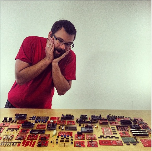
Shields[1] are modular circuit boards that piggyback onto your Arduino to instill it with extra functionality. Want to connect your Arduino to the Internet and post to Twitter? There's a shield for that. Want to make your Arduino an autonomous rover? There are shields for that. There are a LOT of shields out there, all of which can add all sorts of customizations to enhance your Arduino's functionality.
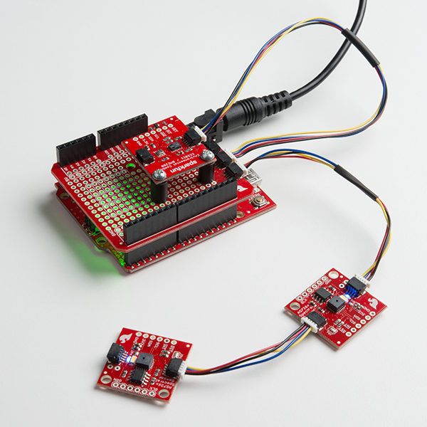
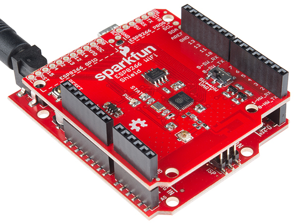
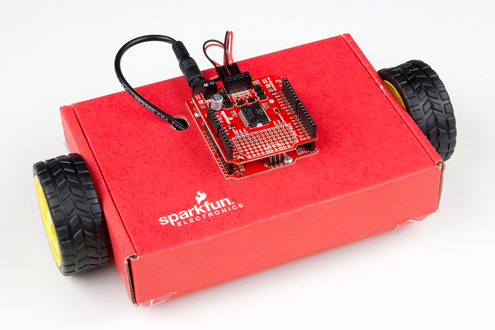
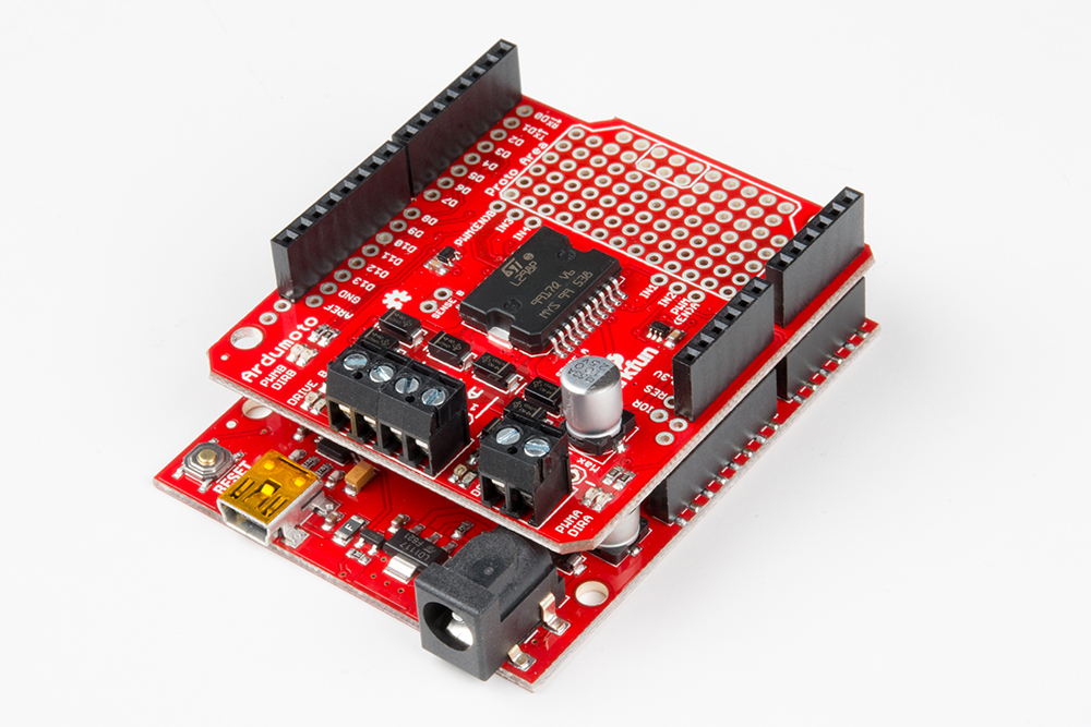
Many Arduino shields are stackable. You can connect multiple shields together to create a stack of Arduino modules. You could, for example, combine a SparkFun RedBoard with a Weather Shield and a WiFi Shield - ESP8266 to create a wireless weather station similar to this Weather Station project.
Shields are often supplied with either an example sketch, or a library. So, not only do they just simply plug into your Arduino, but all you usually need to do to make them work is upload up some example code to the Arduino.
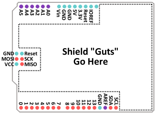
Every Arduino shield must fit the same form factor as the Arduino it mates to.
Shields designed to work on the Arduino Uno R3 form factor have power and ground pins on one eight (previously six) pin header, and analog pins on a six-pin header next to that. Digital pins cover the other edge on the opposite side, an eight-pin header separated from a 10-pin by that weird 0.5" spacing. Some shields also require a connection to the Arduino's ICSP header (the 2x3 programming header on the end).
Some shields use nearly every available pin on the Arduino, while others only use a couple. Some shields communicate with the Arduino via SPI, I2C, or Serial. Other shields use the Arduino's interrupts, analog inputs, and PWM. When stacking shields it's important to make sure they don't use overlapping pins.
Additionally, you will also want to ensure that shield pins are compatible with your development board. If a shield was designed with the ATmega328p in mind, the pin functionality may be in a different location. For example, the XBee shield was designed for the Arduino Uno R3 (an ATmega328P-based board). If you were to use the Arduino Leonardo (an ATmega32U4-based board) or the Arduino Mega 2560 (an ATmega2560-based board), you would need to reroute the connection and redefine the pin definitions. For more information, check out the XBee Shield Hookup guide.
 |
 |
| XBee Shield Pins Rerouted for ATmega2560-Based Arduino | XBee Shield Pins Rerouted for ATmega32U4-Based Arduino |
Also note that there are several Arduino development boards available now that fit the R3 form factor but run at a different logic level than the standard Uno/RedBoard. For example, the Arduino Uno R3 runs at 5V logic where the RedBoard Artemis runs at 3.3V. Quite a few shields can function just fine with a board running at either logic level but you may run into some erratic behavior with level shifting circuits set up to work best with a 5V system. Another potential issue you may run across with a 3.3V logic Arduino is if the shield pulls any of the pins to a 5V reference voltage through something like a pull up resistor.
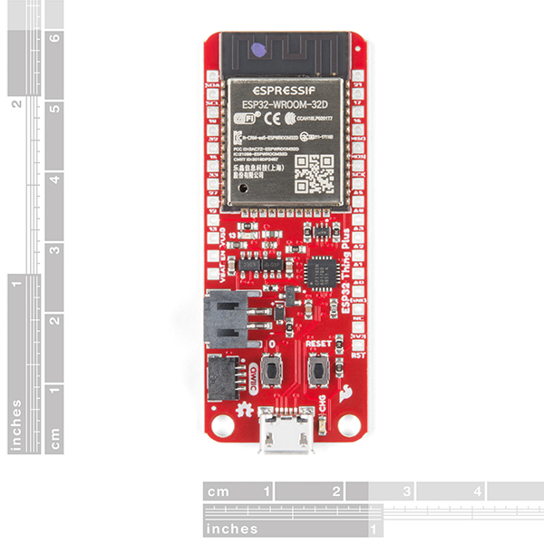
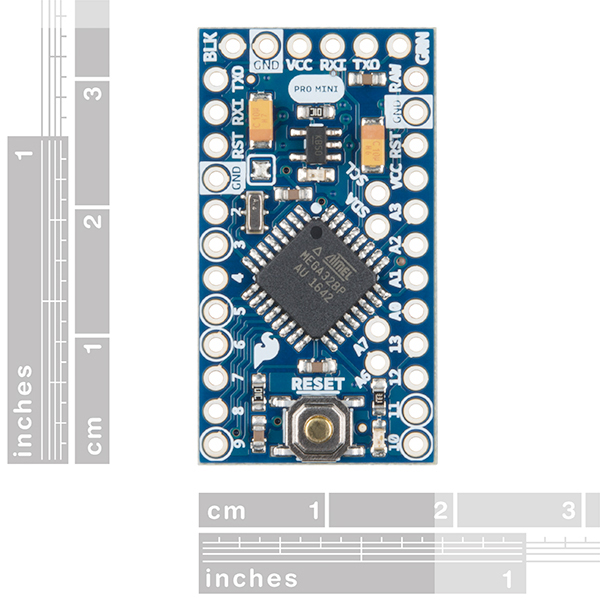
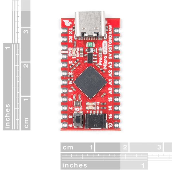
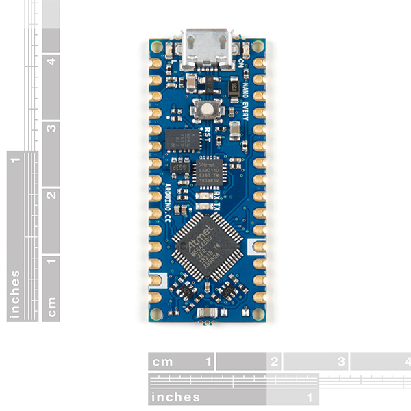
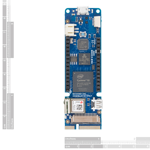
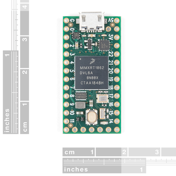
There is a great variety of Arduino shields out there -- too many to ever include in this tutorial. While most adhere to the standard Arduino Uno R3 form factor, some shield designs can vary depending on the development board's footprint and environment. Some of these designs include the Thing Plus, Pro Mini, Pro Micro, Arduino Nano, Arduino MKR, and Teensy footprints.
In the next section, we'll go over a handful of the more popular and unique shields designed for the R3 form factor that SparkFun carries.
The list below describes some of the R3 form factor shields SparkFun carries separated into some loose categories based on their unique functionality. This is not an exhaustive list of all Arduino shields but it will cover most of what SparkFun has to offer. If you want to browse all the shields SparkFun carries, check out the Arduino Shields Category.
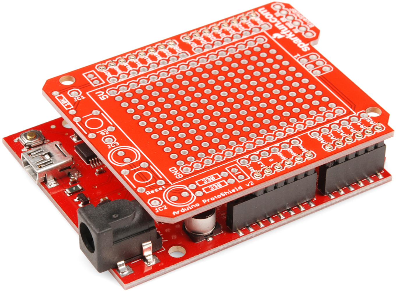
Prototyping shields usually do not augment the functionality of the Arduino like other shields but they help in other ways. Prototyping shields do things like breaking out various pins to screw terminals or create a space to build and test a circuit on the shield.
 |
 |
These shields add different types of wireless technologies to your Arduino. They range from connecting to the Internet for your next IoT Arduino project to receiving and logging the GPS coordinates of your Arduino-based robot and much more!
These shields do not really fit into any of the above categories but we'd still like to highlight them in this list as they add some neat, unique functionality to your Arduino.

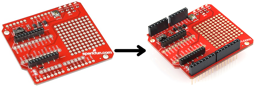
Many shields come without any headers attached. This keeps their final fate open to your interpretation (maybe you'd rather use straight male headers, instead of the usual stackable headers). The following pages will explain how you can turn your drab, header-less shield into a fully functional, ready-to-plug-in module.
Shield assembly requires soldering. Solder helps make a good physical and electrical connection. Without solder, your shield and Arduino will almost certainly not work properly. If it manages to work at all it will be erratic and intermittent at best. If this is your first time soldering, consider checking out our How to Solder: Through-Hole Soldering Tutorial prior to assembling your shield:
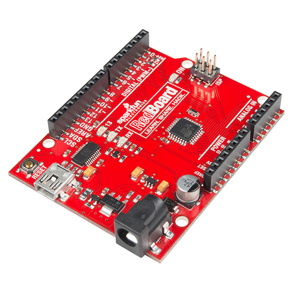
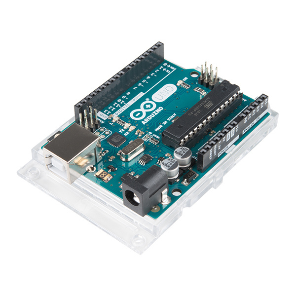
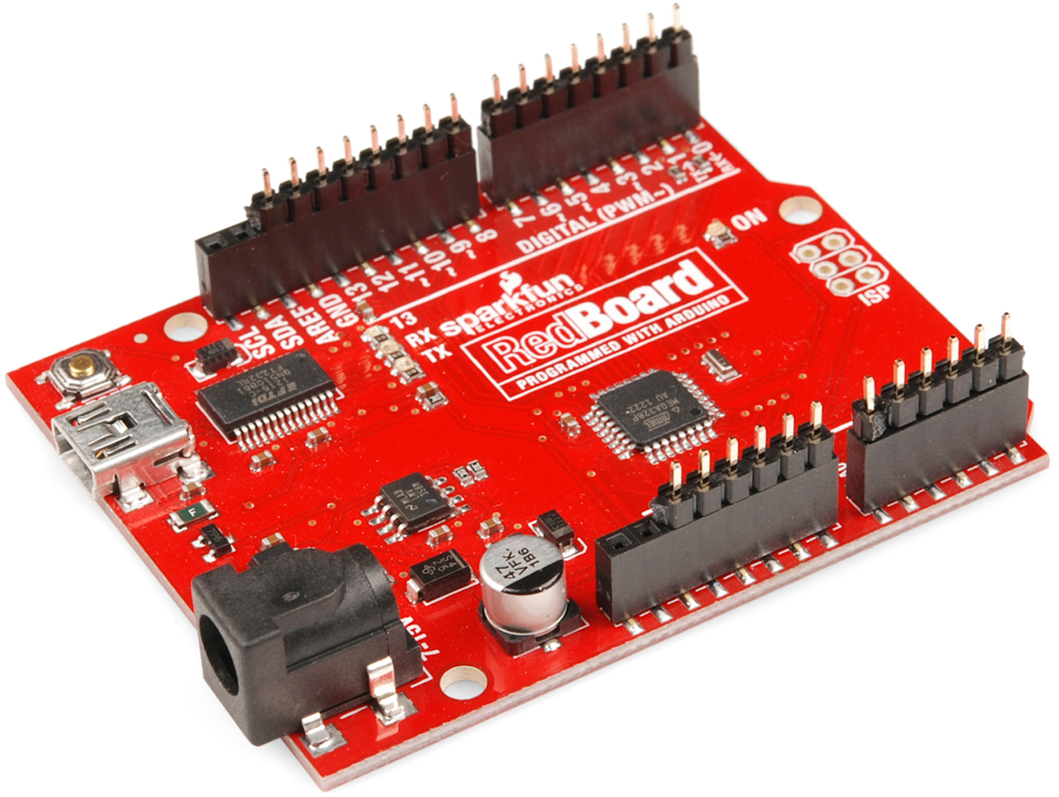
With your shield (or shields) chosen, the only other required materials are a compatible Arduino development board and some headers. The SparkFun RedBoard and Arduino Uno R3 are great options that will work with nearly any Arduino shield with no issues:
And here are some recommended header options:
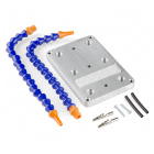
You will also need at least a soldering iron and some solder to assemble your shield. Below are a few soldering iron and solder options along with a couple of kits that will have all the tools necessary to start soldering:

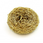
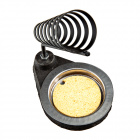
Along with these required tools, these accessories can help make your soldering experience a little easier:
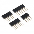
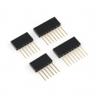
There are all kinds of headers, but there are only two that we recommend for installing on shields: stackable or male.
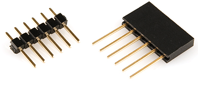
Stackable headers are especially great for stacking shields. They also maintain your ability to plug a jumper wire into any of the Arduino's pins. This tutorial will primarily explain how to install stackable headers. Stackable headers are available individually in 6-pin, 8-pin, and 10-pin varieties (there are other stackable header options for development boards that use different footprints/form factors), or you can buy the headers in packs like the ones shown in the Required Materials section above.
Simple straight male headers are also an option for connecting a shield to an Arduino. Male headers are beneficial in that they create a lower-profile stack when connected to an Arduino. If you plan to stuff your Arduino/shield combo into an enclosure, you may need to consider using male headers. This tutorial focuses on stackable header installation, check the Tips and Tricks section for male header assembly instructions.
Do not install female headers, right-angle male headers, swiss machine-pinned headers, round headers, or a variety of other headers that may exist out there. You really should only use headers that have straight, rectangular, male pins.
Now then, plug in and start warming up those soldering irons. It's time to get soldering!
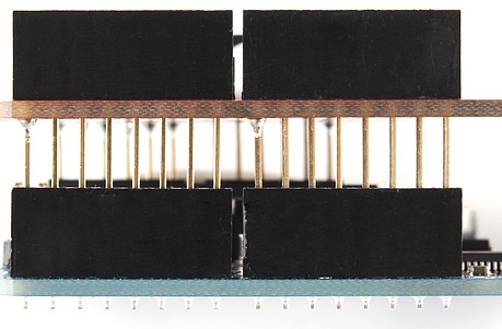
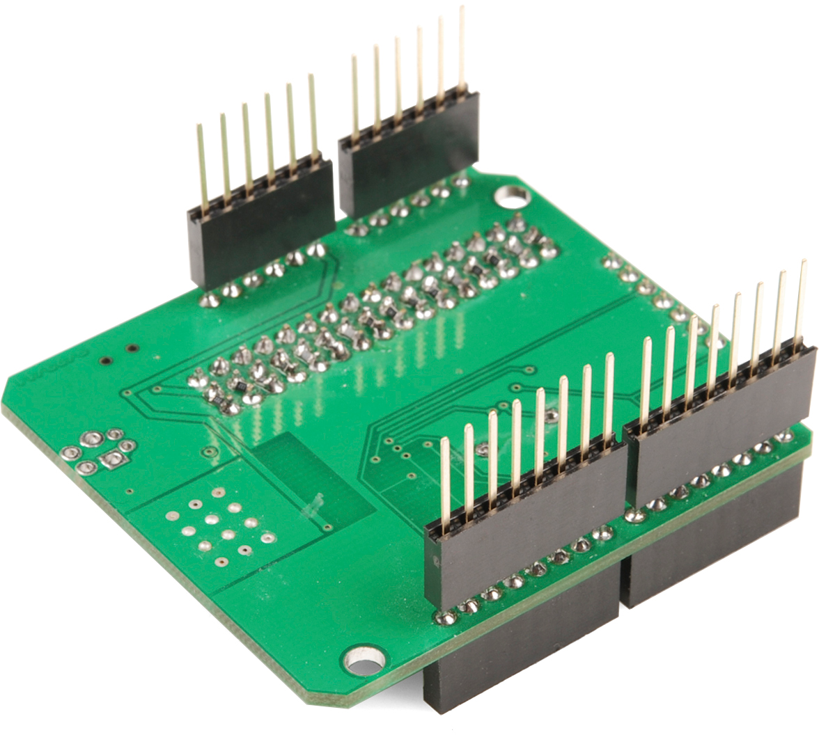
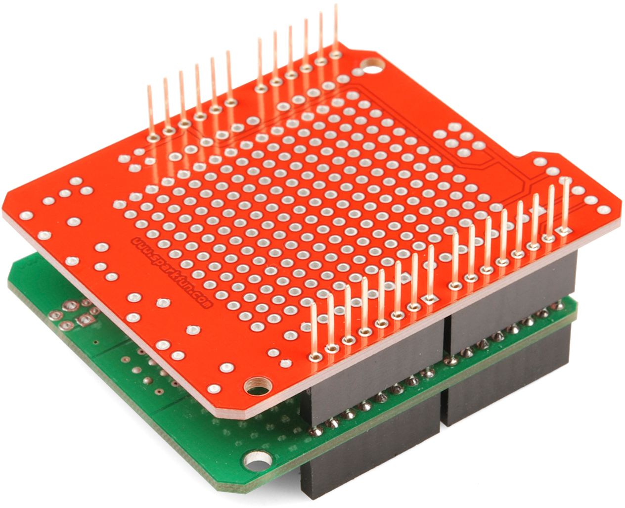
Plug all four headers into the shield. Make sure you insert them in the correct direction. The male pins of the header should enter the top side of the shield and extend out the bottom. This orientation is of utmost importance. Don't solder anything until you've got the headers going the right way!
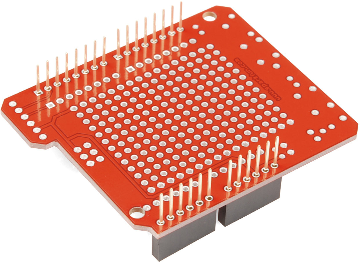
With the headers inserted, flip the shield on its top-side to rest on the black, female side of the headers. Hopefully you've got a nice flat workspace to lay it on. Try to align all headers so they're precisely perpendicular to the shield PCB.
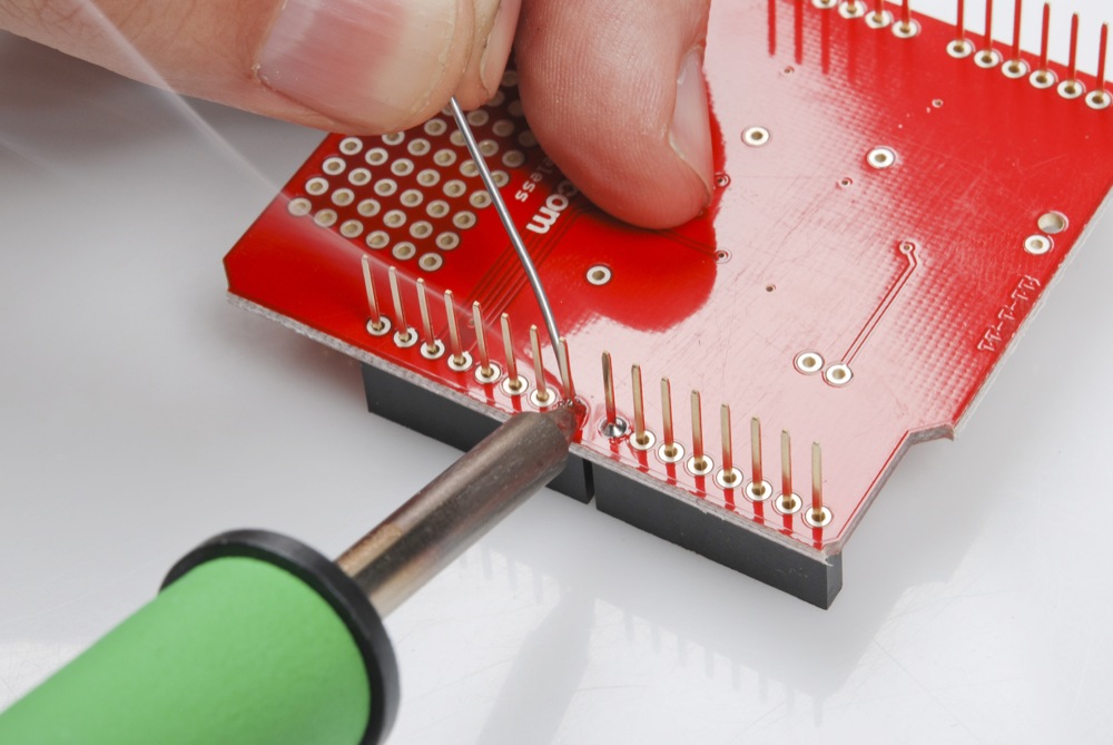
Finally it's soldering time! It's important that each of the headers is at a nice, 90° angle to the PCB. This will ensure that the shield slides straight onto your Arduino and you won't have to bend any pins in doing so.
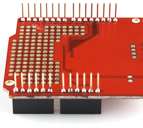
In order to guarantee that each header is straight start by soldering just a single pin on each. That way if they're at a weird angle it will be much easier to re-heat just a single pin while adjusting the alignment.
Four solder joints down, only 24 (to 28) to go!
With those four pins soldered, try plugging the shield partially into your Arduino to test the header's alignment. Make sure your Arduino is not powered while you do this alignment check.
Does everything line up? No pins bending? If not, find the guilty header and try to re-align it. Warm the joint back up with your iron, and slightly move and adjust the header alignment. Also, be careful when pulling the partially soldered shield out of the Arduino. Since all the headers are not soldered, you could easily bend them as you pull it out of the Arduino's female headers.
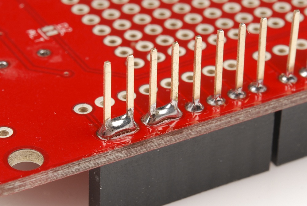
If your headers are all lined up, you can attack the remaining unsoldered header pins. When you're done, you should have 32 shiny volcanoes of solder.
With everything soldered, double check for bad solder joints. Did any of your joints stray into another creating a short? If so, you can take some solder wick to the joint, or just try re-heating the short and "pushing" the solder where you want it.
Also check for cold solder joints - a joint that's got some solder on it, but isn't quite connecting the two solder points together. Cold joints aren't always the easiest to see; look out for joints that aren't as shiny, or pins that still seem loose.
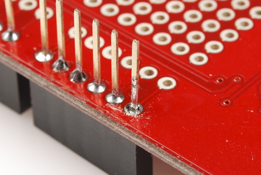
To fix a cold joint, re-heat the solder on the pin, and add just a bit more.
It's usually best practice to power down (unplug) your Arduino before you connect a shield to it. Hopefully all of the pins are still well-aligned and the shield just slides right into the Arduino. Take care not to bend any pins while inserting, and make sure they all go into their mating female headers.
The previous assembly section should detail everything you need to know about simple shield header installation. There are, however, a few tricks we've picked up along the way...
The easiest place to mess up shield assembly is in aligning each of those headers. It's best to avoid soldering the stackable headers while the shield's connected to the Arduino, so the method described in the assembly section is usually best. If you've got a spare shield lying around you can take advantage of another little trick by using it as a header-alignment-jig.
Begin by plugging all of the headers into your spare shield jig.
Then insert the headers into your to-be-soldered shield, and solder them all up. Assuming the spare shield is aligned properly (you may want to check that first), your headers will line up perfectly with your Arduino.
If you value a smaller profile shield installation over the ability to stack shields and connect jumper wires, male headers are an option.
In a way, male headers are actually easier to align and install because you can use your Arduino as a jig. Begin by inserting the headers into your Arduino.
Then line up and plug in the shield, and solder away.
Be somewhat careful using this method. Don't leave the iron on the pins for too long or you risk burning the Arduino's headers underneath. If you're especially worried about burning your Arduino's female headers, you can solder just a single pin on each header, remove the shield, and solder the rest.
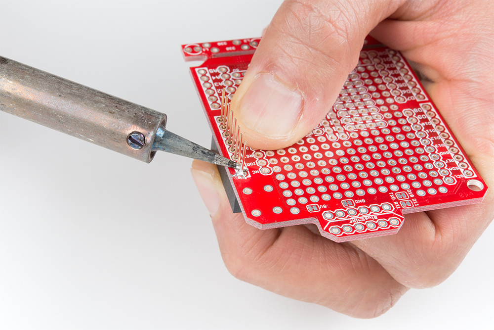
Don't have an extra shield around or your development board does not have any header pins soldered on yet? For those that have the dexterity, you can install a row of headers by holding the pins against the board! You can even try to use tape and sticky tack. Below is an example of installing female headers on the ProtoShield. However, you can follow along with male headers or use this technique to solder headers on development boards as well.
Grab a female stackable header and slide it from the top side of a shield. With your soldering hand, pull the header with your index finger and thumb toward the edge of the board. Using your other hand, push against the header using your index finger and grip the board with your thumb. Hold the header down with your middle finger. Make sure to avoid touching any header pins where the soldering iron will touch.
 |
 |
Grab the soldering iron with your soldering hand and tack on one pin. Repeat for each header. After tacking one pin for each header, you will want to ensure that the pins are straight and perpendicular to your board. If they are not, you can try to reheat the header pin and adjust the header's alignment.
If the headers are aligned, you can solder the rest of the header pins on the board to finish installing the headers on the shield!
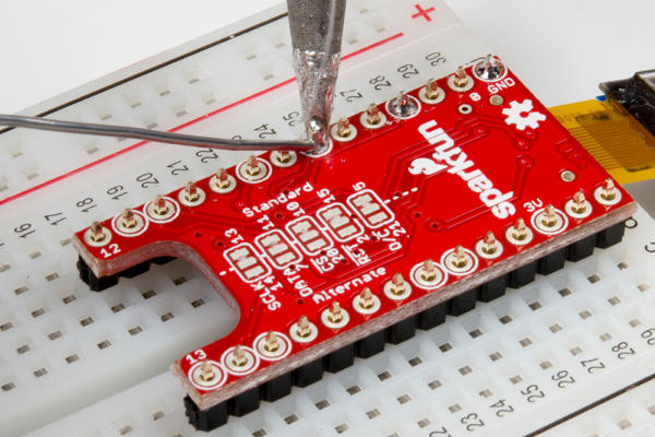
If you are using a shield that does not use the R3 form factor, you may be able to use a breadboard to help solder headers. Below is an example with male headers being soldered on the TeensyView shield for a Teensy and MiniGen shield for a Pro Mini. The Teensy and Pro Mini form factors use breadboard compatible pins on the edge of the board without the weird 0.5" spacing.
 |
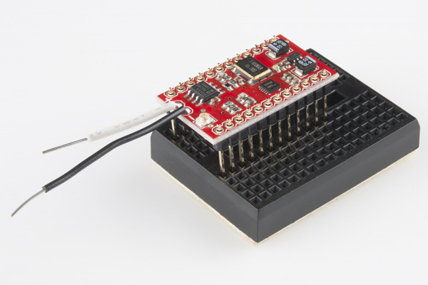 |
| Installing male headers on TeensyView shield for the Teensy with a breadboard. | Installing long male headers on the MiniGen shield for the Pro Mini with a mini-breadboard. |
When using a breadboard, you will also want to be careful soldering the pins to the shield. If you leave the iron on the pins for too long, you will also run the risk of melting the plastic breadboard holding the metal rails as well.
Now that you've got this knowledge under your belt, you can bend just about any Arduino shield to your will! If you're interested in further exploring the world of shields, check out our Arduino Shield category.
Are you just getting started with Arduino or interested in exploring more about using the Arduino IDE? Consider checking out some of these guides to help you get started:
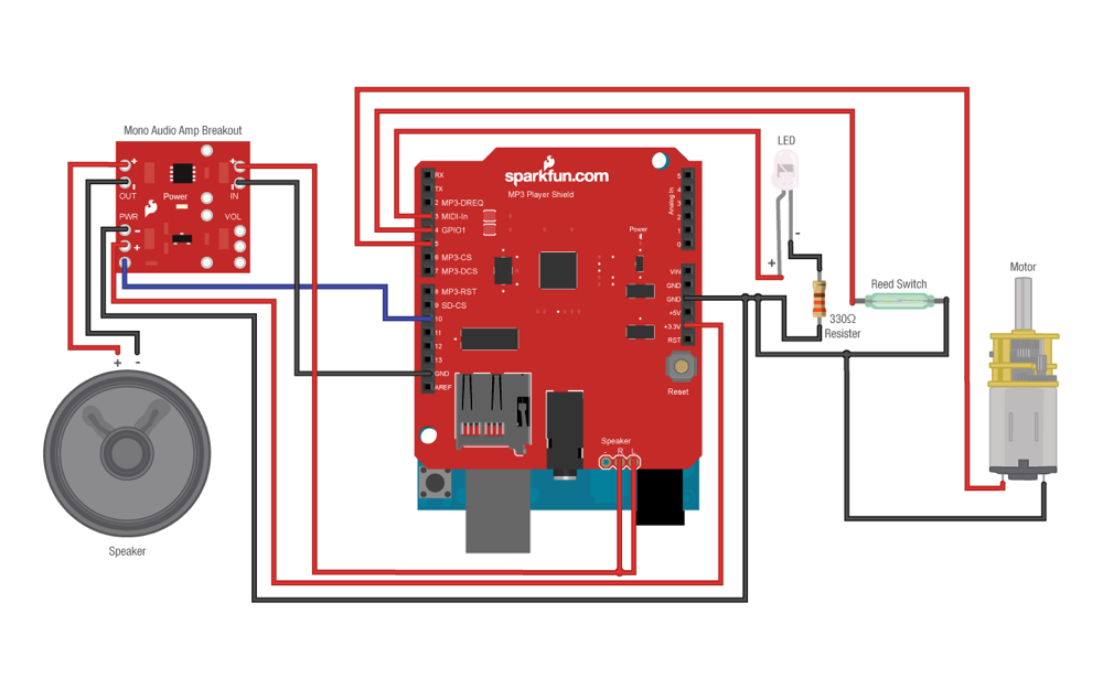
Looking for some project inspiration for your Arduino shield? Here are some fun project tutorials focused on using an Arduino shield:
learn.sparkfun.com | CC BY-SA 3.0 | SparkFun Electronics | Niwot, Colorado