GPS Logger Shield Hookup Guide
 jimblom
 Introduction
The SparkFun GPS Logger Shield equips your Arduino with access to a GPS module, µSD memory card socket, and all of the other peripherals you'll need to turn your Arduino into a position-tracking, speed-monitoring, altitude-observing wonder logger.
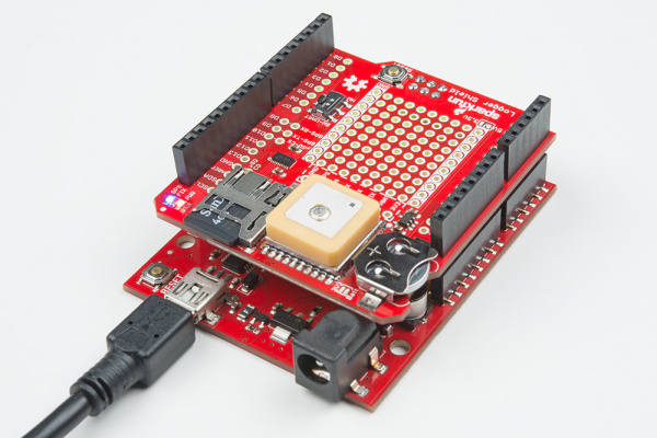
The shield is based around a GP3906-TLP GPS Module -- a 66-channel GPS receiver featuring a MediaTek MT3339 architecture and an up to 10Hz update rate. The GPS module will stream constant position updates over a simple serial UART, which you can then log to a µSD card and/or use for other position or time-tracking purposes.
Everything on the shield is highly configurable: A switch allows you to select the GPS module's UART interface between either hardware or software ports, the µSD card operates over a hardware SPI port, which should be compatible with most Arduino layouts, and extra prototyping space should allow you to add those last, few components you need to complete your project.
Covered In This Tutorial
This tutorial aims to document all things GPS Logger Shield related, including both the hardware and software required to get it up-and-running. It's split into the following sections:
- Hardware Overview -- An overview of the schematic, layout, and features of the SparkFun GPS Logger Shield.
- Hardware Setup -- Tip for assembling the GPS Logger Shield to best match your project needs.
- Example Arduino Sketches
- GPS Serial Passthrough -- A simple sketch you can use to verify functionality of your GPS Logger Shield, and get an idea of what kind of data the GP3906 GPS module produces.
- TinyGPS++ Serial Streaming -- Using the TinyGPS++ Arduino library to parse the GPS module's NMEA strings into latitude, longitude, altitude, speed, and more.
- µSD Card GPS Logging -- Finally, we'll plug the parsed GPS data into a CSV file and save it to a µSD card.
Suggested Materials
There are a few extra components you'll need to get the GPS Logger Shield fully up-and-running:
Most importantly, you'll need an Arduino or Arduino-compatible development board. The GPS's serial and µSD SPI ports should be compatible with almost all Arduino-sized development boards. That includes classics, like the Arduino Uno and SparkFun RedBoard, and newer models, like the Arduino Leonardo, Genuino 101, and SparkFun SAMD21 Dev Breakout.
SparkFun SAMD21 Development Breakout
DEV-13672
Arduino Leonardo with Headers
DEV-11286
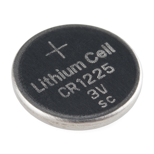
We also highly recommend a 12mm Coin Cell Battery, which fits into the GPS Shield's battery holder. The GP3906 GPS module requires some sort of voltage on its battery supply input. If you don't have a battery, make sure you read the VBAT section of the hardware overview carefully.
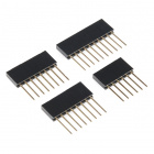
You'll also need to solder some headers into the shield, to create a solid mechanical and electrical connection between it and the Arduino. We recommend the Arduino R3 Stackable Header Pack, but a set of male headers may also suit your needs.


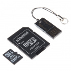
MicroSD Card with Adapter - 8GB
COM-11609Finally, if you intend on logging the GPS data to a µSD card, you may want to grab a µSD Card and SD Adapter. The Arduino SD library should support most µSD cards formatted with FAT16 or FAT32 file systems.
Suggested Reading
This is a beginner-level tutorial -- and the GPS Logger Shield is a beginner-friendly product -- but there are a few concepts you should be comfortable with before continuing on. If any of these subjects sound unfamiliar, considering reading those tutorials before continuing on.
- GPS Basics -- This tutorial is a great primer on the wonders of GPS. Learn how we get find our position on the globe by listening to (at least) four satellites send a timestamp and aerial position.
- Serial Communication -- The GP3906 communicates via a simple, serial UART. This tutorial will familiarize you with serial-related concepts like RX, TX, and baud rate.
- How to Solder: Through-Hole Soldering -- If you've never soldered before, now's a great time to start, and this is a great tutorial to learn from.
- Installing an Arduino Library -- We'll use a pair of fantastic Arduino libraries to log GPS data to an SD card.
How to Solder: Through-Hole Soldering
Serial Communication
GPS Basics
Installing an Arduino Library
Hardware Overview
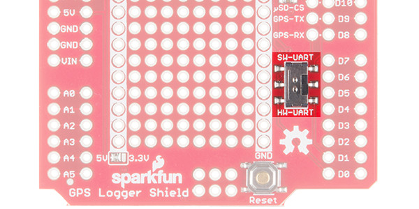
For a quick overview of the components and features of the GPS Logger Shield, refer to the image below:
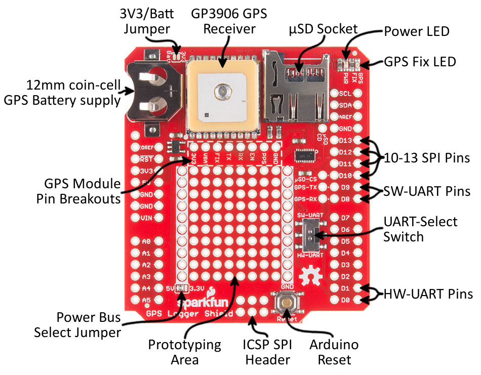
The rest of this section will dive into some of the more critical components of the shield, including power supply requirements and UART and SPI interface configurations.
Powering the GPS Logger Shield
The GPS Logger Shield's main voltage supply is taken from the Arduino 5V header pin. This voltage is regulated down to 3.3V, which is supplied to both the GPS module and the µSD card.
These two components should consume around 30mA on average, but they may very occasionally spike to upwards of 100mA.
Logic-Level Shifting
The shield includes a TXB0108 8-Channel Level Shifter, which shifts voltage levels between the Arduino and 3.3V GPS UART and µSD SPI signals. Regardless of whether your Arduino runs at 5V or 3.3V, you shouldn't have to concern yourself with shifting voltages between either component.
The Arduino-side logic-level voltage is set by the IOREF pin, which most Arduino development boards connect to either 5V or 3.3V.
⚡ If your Arduino board doesn't have an IOREF pin, or if no voltage is supplied on that pin, you will need to set the IOREF voltage manually. The shield includes a jumper on the back-side of the board, labeled IOREF-SEL, which you can use to set the IOREF voltage to either 3.3V or 5V.
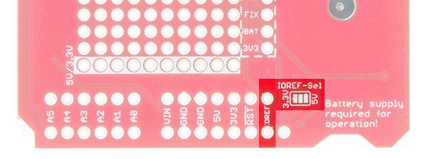
If your Arduino board doesn't have an IOREF pin, set this jumper to match your desired logic level.
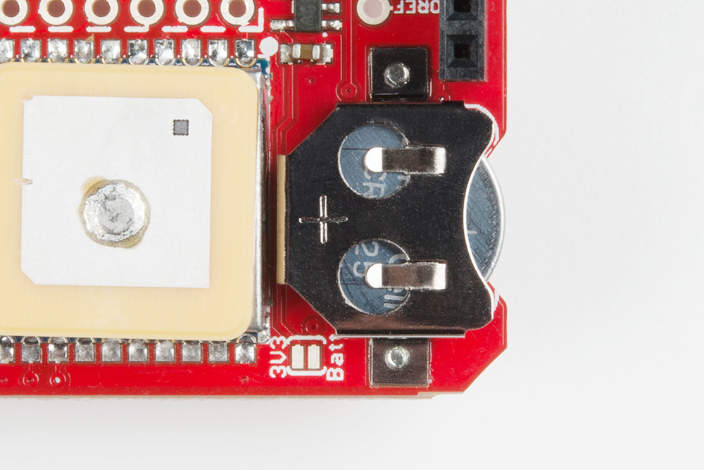
GP3906 Battery Supply (VBAT)
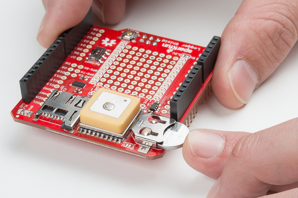
The GP3906 is a great, little module, but it has one, big quirk: A supply voltage between 2.0-4.3V is required on the VBAT pin. If you have a 12mm coin cell battery, supplying that voltage is as easy as pushing it into the battery socket. When you insert the battery, make sure you slot it in + side facing up.
If you don't have a battery handy, there are a few workarounds. You can grab a soldering iron, and short the 3V3-Batt jumper, next to the battery socket.
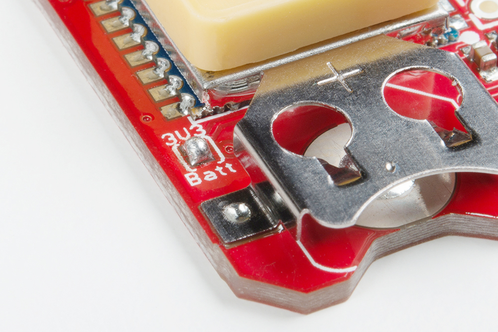
Or you can wire the broken out VBAT pin to any voltage supply between 2.0-4.3V.
Supplying the GP3906 with a backup battery supply ensures that its real-time clock (RTC) will continue to tick, even when the rest of the board is powered off. That allows the module to get faster GPS fixes when it initially powers up. It doesn't consume a lot of power -- we've measured around 5-6µA, -- so a 12mm coin cell battery could keep the board "running" (in sleep mode) for about a year.
GPS Pin Breakout's
Most of the GPS input, output, and power pins are connected to something on the GPS Logger Shield, but they're all also broken out to this 8-pin header.
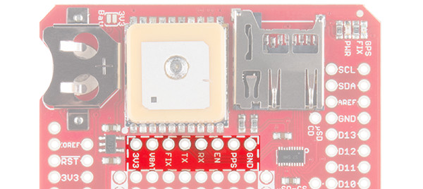
Here's a quick overview of each pin and its function:
| Pin Label | In/Out | Board Connection | Pin Description |
|---|---|---|---|
| GND | In | Ground | GPS module ground (0V reference) |
| PPS | Out | 1 pulse-per-second time reference | |
| EN | In | Active-high chip-enable – pull low to reset or turn off | |
| RX | In | Arduino TX/D9 | Serial data input |
| TX | Out | Arduino RX/D8 | Serial data output |
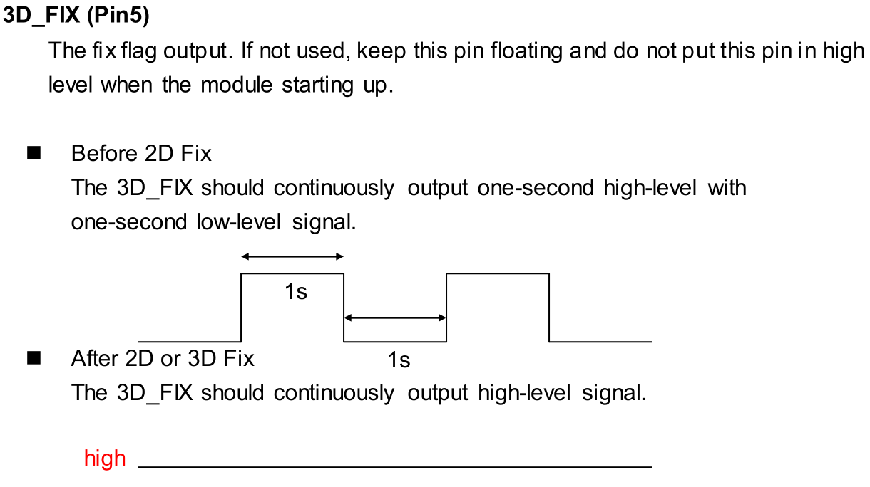
| FIX | Out | GPS Fix LED | GPS fix indicator – blinks before a fix, HIGH once a fix is valid |
| VBAT | In | 12mm coin cell socket | Backup power – keeps the RTC running (2.0-4.3V input range) |
| 3V3 | In | On-board 3.3V regulator | 3.3V power supply input |
The PPS and EN pins are left unconnected. You're free to wire them up to any Arduino pin should you need either a pulse-per-second signal, or extra control of the GPS module's operation.
Selecting the Serial Port
The GPS module communicates via a simple, UART (serial) interface. The UART-select switch allows you to switch that interface between either the Arduino's hardware UART -- on pins D0 and D1 -- or a SoftwareSerial port on pins D8 and D9.
Should you need a reference, this table shows the map between GPS module and Arduino UART(s):
| GPS Pin | Arduino Software UART Pin | Arduino Hardware UART Pin |
|---|---|---|
| RX | 9 | 1 (TX) |
| TX | 8 | 0 (RX) |
If you're using an Arduino Uno or any development board with one, pre-occupied hardware UART, you may be forced to use the software serial port. Fortunately, the GPS module's baud rate defaults to a slow, steady 9600 bps, which SoftwareSerial shouldn't have a problem handling.
If you need to move the software serial port pins, they can be custom-routed to any other pin by cutting the solder jumpers between pins GPS-RX and D8 and/or GPS-TX and D9.
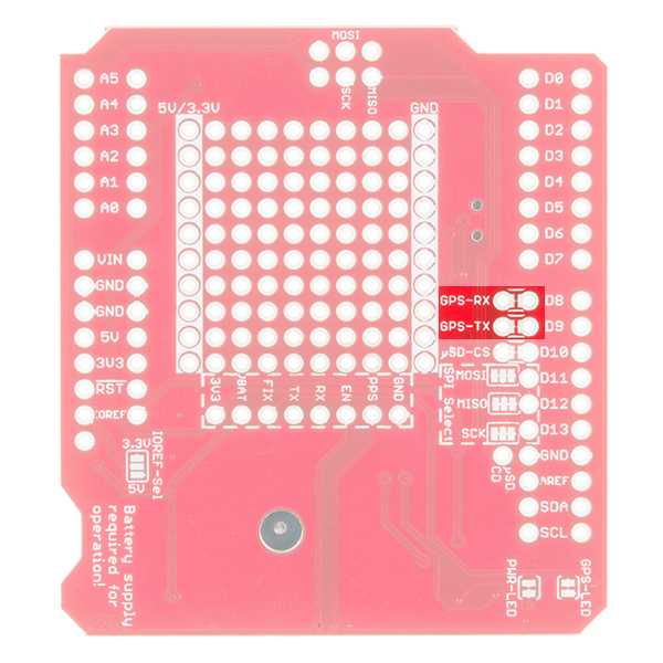
Once those jumpers are cut, you can wire the GPS-RX and GPS-TX pins to any other pins you'd like.
Selecting the µSD SPI Pins
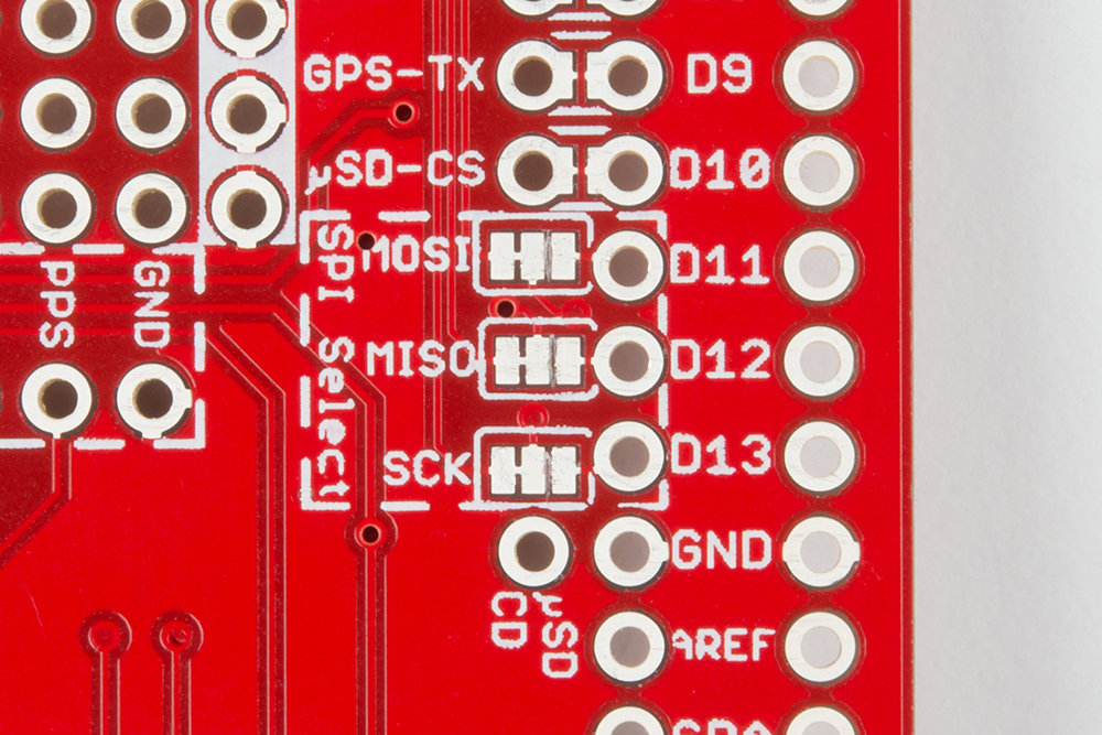
On older Arduino boards, finding the SPI port was pretty simple -- it'd be on pins 10-13, mapping out to CS, MOSI, MISO, and SCLK respectively. On more recent Arduino board releases, however, these pins are just as likely to be found on only the 6-pin, 2x3 SPI header. The GPS Logger Shield maps the µSD SPI pins to both of these headers, in order to support as many development boards as possible.
A trio of three-way solder jumpers can be used to modify which Arduino pins are routed to the µSD card's SPI I/O's.
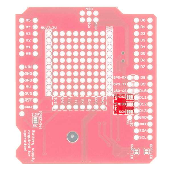
The middle pad of these jumpers carries the signal to/from the µSD card. The pads toward the inside of the board carry signals to the SPI header, and the pads toward the outside carry signals to pins 10-13.
Boards that map SPI to pins 10-13 include the Arduino Uno, RedBoard, Arduino Pro's, and most ATmega328P-based boards. If you're using any of these boards, it should be safe to leave the jumper's untouched (as they're also, likely, shorted together on the Arduino).
Boards that only map SPI to the 2x3 SPI header include the Arduino Leonardo (and other most ATmega32U4-based boards), Arduino Due, and the Arduino Zero (and most ATSAMD21-based boards). On these boards, you'll need to cut the solder jumpers connecting the middle pad to the D11-, D12-, and D13-side pads. The µSD_CS connected to pin D10 can be defined on any pin so it does not have to be modified.
Check below for more information about the **µSD SPI Jumpers**.
Power and GPS Fix Status LEDs
This pair of LEDs on the corner of the shield are a handy tool for initial troubleshooting. The red PWR LED is attached to the output of the shield's on-board 3.3V regulator. If the shield is getting power, this LED should be on.
The blue GPS FIX LED is connected the GP3906's "3D_FIX" pin. It can be used to identify whether the GPS module has a proper fix or not. When you initially power the shield up, the LED should blink -- indicating it's trying to find a fix. Once the LED turns solidly on, you can rest assured that your GPS module has a good fix on your location.
Both of these LEDs have solder jumpers underneath, should you find the need to disable either of them. A quick slice between the pads is all it takes to remove them from the circuit. This might be useful if you're using the GPS Logger Shield in a low-power application, where even the handful of milliamps consumed by the LEDs means months off a project's battery lifetime.
Hardware Setup
Assembly of the GPS Logger Shield mostly comes down to soldering something to all of the 6, 8, and 10-pin Arduino headers. We usually recommend Arduino R3 Stackable Headers for this job, but male headers can work -- as long as this is the top board in a shield stack.

If your application requires use of the 6-pin, 2x3 SPI header, you may also want to solder female headers to those pins (make sure they're pointing down, and slot easily into your Arduino's male SPI pins).
If you've never soldered an Arduino shield before, check out our Arduino Shield Assembly tutorial for some tips.
Pre-Flight Checklist
Before you get the go-ahead for GPS Shield'ing, make sure you double-check these common pitfalls one last time:
Battery (VBAT) Power Supply
Make sure you have a reliable power source supplying the GPS module's VBAT pin. If you have a shiny, new 12mm coin cell battery plugged in, that's perfect. Otherwise, make sure you've either shorted the 3.3V/VBAT jumper, or are supplying something to the GPS module's VBAT breakout.
UART Selected
Make sure you have the UART-select switch pointing towards your preferred UART. If you're using an Uno, Redboard, or any other ATmega328P-based Arduino, you'll most likely need to have the switch pointing towards SW-UART, assuming the hardware UART is used for programming and serial debugging.
If you're using a Leonardo (ATmega32U4-based boards), Zero (ATSAMD21-based boards), or any other Arduino that has a dedicated and free hardware UART on pins 0/1, we recommend leaving the switch in the HW-UART position.
µSD SPI Jumpers
Planning on logging data to a µSD card? Make sure the SPI jumpers are set accordingly. If you're using an Uno, Redboard, or any other ATmega328P-based Arduino, you can probably leave the jumpers untouched. SPI should be broken out to both pins 10-13 and the SPI header anyway.
If you're using a Leonardo (ATmega32U4-based boards), Zero (ATSAMD21-based boards), or any other Arduino that doesn't break the SPI signals to pins 10-13, you'll want to cut the three SPI-select jumpers between the middle pad and the D11-D13 pins. That will free up those pins for other purposes in your project. The µSD_CS connected to pin D10 can be defined on any pin so it does not have to be modified.
If you're relying on the SPI port from the 2x3-pin ICSP header, don't forget to solder headers to the SPI port!
Software Serial and SPI On Other Microcontrollers
Software Serial
The demo code was originally designed for the ATmega328P on the Arduino Uno. If you were using it with ATmega2560 (i.e. Arduino Mega 2560) or ATmega32U4 (i.e. Arduino Leonardo, Pro Micro 5V/16MHz, Pro Micro 3.3V/8Mhz, FioV3, etc.), you would need to re-configure the software serial pin definitions and adjust the connections. Not all the pins can support change interrupts for a serial Rx pin depending on what Arduino microcontroller is used. You will need to redefine pin definitions and reroute the connection.
For more information about the limitations, try looking at the Arduino reference language for the Software Serial library.
Redefining for Software Serial Pins
To use the GPS logger shield on an Arduino Mega 2560, you would just need to adjust the software serial pin definitions in the code where it says:
language:c
#define ARDUINO_GPS_RX 9 // Arduino RX pin connected to GPS TX
#define ARDUINO_GPS_TX 8 // Arduino TX pin connected to GPS RX
Let's change the software serial pins by using the analog pins A9 and A8, respectively.
language:c
#define ARDUINO_GPS_RX A9 // Arduino RX pin connected to GPS TX
#define ARDUINO_GPS_TX A8 // Arduino TX pin connected to GPS RX
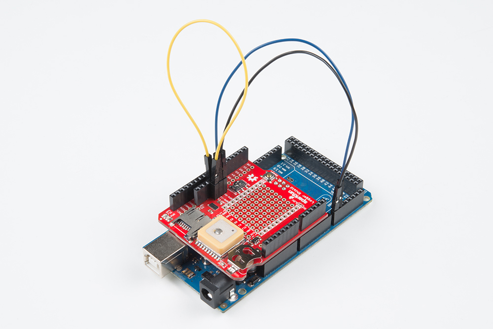
Rerouting for Software Serial Pins
Once you adjust the code, make sure to rewire your connections. Cut across the trace between the plated through holes using a hobby knife. There is a red solder mask above the trace so make sure that the trace is completely cut.
Once the trace has been cut, solder header pins or wires to the plated through holes. To easily switch between different development boards, female headers were added.

Once soldered, two male to male jumper wires were added to the through hole pins closest to GPS-Rx and GPS-Tx. With the rewired connects, GPS-Tx was rerouted to pin A9 and GPS-Rx was rerouted to pin A8. While not necessary, the yellow jumper wire was added to easily reroute the SPI's CS pin to another I/O with the data logging example.
SPI
The demo code was originally designed for the ATmega328P on the Arduino Uno. You would only need to worry about adjusting the SPI pins if you were using the CSV_Logger_TinyGPSPlus.ino logging example. Just like software serial, you would need to reroute the connection.
For more information about the limitations, try looking at the reference language for the SPI library.
Rerouting for SPI Pins
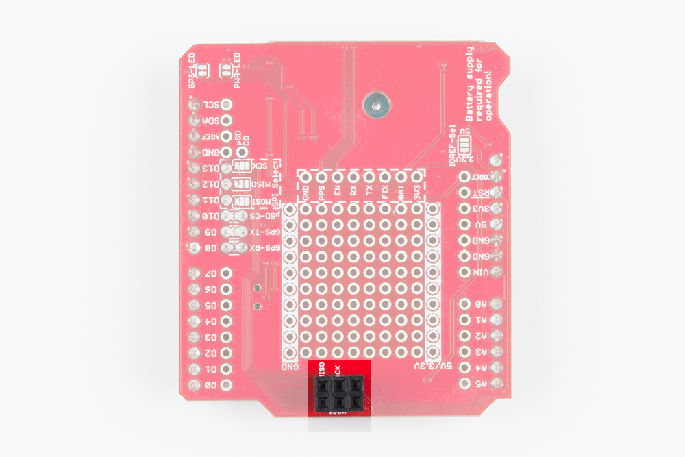
To use the GPS Logger Shield on the Arduino Mega 2560, you would just need to reroute the SPI pins. Using a hobby knife, cut the trace between the center and right pads for MOSI, MISO, and SCK.
Once cut you have the option of soldering one 2x3 female header or two 1x3 stackable headers to the ICSP pins.
Make sure to solder from the top side of the shield so that the female header pins face down toward the Arduino's ICSP pins.
Once the headers are soldered, stack it on the Arduino Mega 2560 and reroute the software serial pins. The CS pin can be cut and rerouted to another pin on the microcontroller. However, the default trace on pin 10 will still work.
Example Sketch: GPS Serial Passthrough
Now that your hardware is all set up, we have three pieces of example code to give you a taste of the GPS Logger Shield's functionality. This first example isn't all that useful, but it will, at least, make sure everything's working. Plus it'll show you the raw ugliness of NMEA GPS strings and make you appreciate great libraries like TinyGPS even more.
This example doesn't require any additional libraries. Simply plug the shield into your Arduino and upload the example code. We've got a couple examples, depending on which Arduino and/or serial port you're using.
Note: This example assumes you are using the latest version of the Arduino IDE on your desktop. If this is your first time using Arduino, please review our tutorial on installing the Arduino IDE.
If you have not previously installed an Arduino library, please check out our installation guide.SoftwareSerial Port Example
If you're using an Arduino Uno, Redboard, any other ATmega328P-based Arduino, and have the UART-select switch in the SW-UART position, upload this piece of example code to your Arduino:
language:c
    /******************************************************************************
Basic_Passthrough_Software.ino
Basic Software Serial GPS Passthrough
By Jim Lindblom @ SparkFun Electronics
February 9, 2016
https://github.com/sparkfun/GPS_Shield

This example uses SoftwareSerial to communicate with the GPS module on
pins 8 and 9. SoftwareSerial should work on most Arduinos, but it's a
necessity on Arduino Uno's, RedBoard's and any other Arduino
based around an ATmega328P.

After uploading the code, open your serial monitor, set it to 9600 baud, and
watch the GPS module's NMEA strings begin to flow by. See if you can pick
out the latitude and longitude.

Resources:
SoftwareSerial Library (included with Arduino)

Development/hardware environment specifics:
Arduino IDE 1.6.7
GPS Logger Shield v2.0 - Make sure the UART switch is set to SW-UART
Arduino Uno, RedBoard, Pro, etc.
******************************************************************************/

#include <SoftwareSerial.h> // Include the SoftwareSerial library
#define ARDUINO_GPS_RX 9 // Arduino RX pin connected to GPS TX
#define ARDUINO_GPS_TX 8 // Arduino TX pin connected to GPS RX
#define GPS_BAUD_RATE 9600 // The GPS Shield module defaults to 9600 baud
// Create a SoftwareSerial object called gps:
SoftwareSerial gpsPort(ARDUINO_GPS_TX, ARDUINO_GPS_RX);

// We'll also define a more descriptive moniker for the Serial Monitor port.
// This is the hardware serial port on pins 0/1.
#define SerialMonitor Serial

void setup()
{
  gpsPort.begin(GPS_BAUD_RATE);
  SerialMonitor.begin(9600);
}

void loop()
{
  if (gpsPort.available()) // If GPS data is available
    SerialMonitor.write(gpsPort.read()); // Read it and print to SerialMonitor
  if (SerialMonitor.available()) // If SerialMonitor data is available
    gpsPort.write(SerialMonitor.read()); // Read it and send to GPS
}
Copy and paste the above code into your Arduino IDE. You can also download all of the example sketches from our GitHub repository.
This example uses the SoftwareSerial library to communicate with the GPS module, and leaves the hardware serial port for debugging with the serial monitor.
Hardware Serial Port Example
If you're using an Arduino Leonardo, Arduino Due, Arduino Zero, or any other Arduino with a free UART on pins 0/1, set the UART-select switch to HW-UART, and upload this example:
language:c
    /******************************************************************************
Basic_Passthrough_Hardware.ino
Basic Hardware Serial GPS Passthrough
By Jim Lindblom @ SparkFun Electronics
February 9, 2016
https://github.com/sparkfun/GPS_Shield

This example uses an Arduino's hardware serial port -- on pins 0 and 1 -- to
communicate with the GPS module.

Hardware serial should work on any Arduino's with a free hardware serial
UART on pins 0/1. That includes Arduino Leonardo, Zero, Due, and SparkFun's
SAMD21 Dev Board.

After uploading the code, open your serial monitor, set it to 9600 baud, and
watch the GPS module's NMEA strings begin to flow by. See if you can pick
out the latitude and longitude.

Development/hardware environment specifics:
Arduino IDE 1.6.7
GPS Logger Shield v2.0 - Make sure the UART switch is set to HW-UART
Arduino Leonardo, Arduino Zero, Arduino Due, SparkFun SAMD21 Dev Board, etc
******************************************************************************/

#define GPS_BAUD_RATE 9600 // The GPS Shield module defaults to 9600 baud

// Define the serial monitor port. On the Leonardo this is 'Serial'
//  but on other boards this may be 'SerialUSB'
#define SerialMonitor Serial // e.g. Arduino Leonardo
// Define the harware serial port on pins 0/1. On the Leonardo this is 'Serial1'
//  but on other boards this may be 'Serial'
#define gpsPort Serial1 // e.g. Arduino Leonardo
// See https://www.arduino.cc/en/Reference/Serial to find out which Serial ports
//  you should use in the defines above.

void setup()
{
  SerialMonitor.begin(9600); // Initialize the serial monitor port at 9600 baud
  gpsPort.begin(GPS_BAUD_RATE); // The GPS module's default baud is 9600
}

void loop()
{
  if (gpsPort.available()) // If GPS data is available
    SerialMonitor.write(gpsPort.read()); // Send it to the serial monitor
  if (SerialMonitor.available()) // If data is sent to the serial monitor
    gpsPort.write(SerialMonitor.read()); // send it to the GPS module
}
You may have to alter either or both of the serial port #defines at the top of the code. Refer to your development board's datasheet or product info page for more information on which serial port is which.
Using the Serial Passthrough Sketch
Once you've uploaded the sketch, open up your serial monitor and set the baud rate to 9600. You should immediately begin to see GPS NMEA data begin to flow by at a rate of 1Hz.
For example, one set of strings may look like:
$GPRMC,235316.000,A,4003.9040,N,10512.5792,W,0.09,144.75,141112,,*19
$GPGGA,235317.000,4003.9039,N,10512.5793,W,1,08,1.6,1577.9,M,-20.7,M,,0000*5F
$GPGSA,A,3,22,18,21,06,03,09,24,15,,,,,2.5,1.6,1.9*3E
If you don't see anything in the serial monitor, make sure the UART-select switch is in the correct position. Also double check that the blue "GPS Fix" LED is at least blinking. If it's not, the module may not be receiving power. Don't forget to supply VBAT!
If you're still not having any luck, get in touch with our technical support team.
NMEA strings are the standard message format produced by almost all GPS receivers. They can relay all sorts of information including the time, latitude, longitude, altitude, and number of satellites visible, but unless you're an incredibly fast parser, these sentences will mostly mean nothing. Fortunately, the Arduino can read those strings, parse them for you, and give you more human-readable pieces of data.
Example Sketch: TinyGPS Serial Streaming
A couple of our favorite GPS-parsing Arduino libraries are TinyGPS and TinyGPS++. These libraries simplify the task of parsing the excessive NMEA strings, leaving us with just the few bits of data we care about.
You will need to install the libraries in your Arduino IDE. Visit the links above to download them. Reference our Installing an Arduino Library tutorial for any additional library-installing help you may need.
TinyGPS++ Example
Here's a quick example, which uses the TinyGPS++ library to parse NMEA strings for position, altitude, time, and date. Copy and past the code below into your Arduino IDE and upload to your board.
language:c
/******************************************************************************
  TinyGPSPlus_GPS_Shield.ino
  TinyGPS++ Library Example for the SparkFun GPS Logger Shield
  By Jim Lindblom @ SparkFun Electronics
  February 9, 2016
  https://github.com/sparkfun/GPS_Shield

  This example uses SoftwareSerial to communicate with the GPS module on
  pins 8 and 9. It uses the TinyGPS++ library to parse the NMEA strings sent
  by the GPS module, and prints interesting GPS information to the serial
  monitor.

  After uploading the code, open your serial monitor, set it to 9600 baud, and
  watch for latitude, longitude, altitude, course, speed, date, time, and the
  number of visible satellites.

  Resources:
  TinyGPS++ Library  - https://github.com/mikalhart/TinyGPSPlus/releases
  SoftwareSerial Library

  Development/hardware environment specifics:
  Arduino IDE 1.6.7
  GPS Logger Shield v2.0 - Make sure the UART switch is set to SW-UART
  Arduino Uno, RedBoard, Pro, etc.
******************************************************************************/

#include <TinyGPS++.h> // Include the TinyGPS++ library
TinyGPSPlus tinyGPS; // Create a TinyGPSPlus object

#define GPS_BAUD 9600 // GPS module baud rate. GP3906 defaults to 9600.

// If you're using an Arduino Uno, RedBoard, or any board that uses the
// 0/1 UART for programming/Serial monitor-ing, use SoftwareSerial:
#include <SoftwareSerial.h>
#define ARDUINO_GPS_RX 9 // GPS TX, Arduino RX pin
#define ARDUINO_GPS_TX 8 // GPS RX, Arduino TX pin
SoftwareSerial ssGPS(ARDUINO_GPS_TX, ARDUINO_GPS_RX); // Create a SoftwareSerial

// Set gpsPort to either ssGPS if using SoftwareSerial or Serial1 if using an
// Arduino with a dedicated hardware serial port
#define gpsPort ssGPS  // Alternatively, use Serial1 on the Leonardo

// Define the serial monitor port. On the Uno, and Leonardo this is 'Serial'
//  on other boards this may be 'SerialUSB'
#define SerialMonitor Serial

void setup()
{
  SerialMonitor.begin(9600);
  gpsPort.begin(GPS_BAUD);
}

void loop()
{
  // print position, altitude, speed, time/date, and satellites:
  printGPSInfo();

  // "Smart delay" looks for GPS data while the Arduino's not doing anything else
  smartDelay(1000);
}

void printGPSInfo()
{
  // Print latitude, longitude, altitude in feet, course, speed, date, time,
  // and the number of visible satellites.
  SerialMonitor.print("Lat: "); SerialMonitor.println(tinyGPS.location.lat(), 6);
  SerialMonitor.print("Long: "); SerialMonitor.println(tinyGPS.location.lng(), 6);
  SerialMonitor.print("Alt: "); SerialMonitor.println(tinyGPS.altitude.feet());
  SerialMonitor.print("Course: "); SerialMonitor.println(tinyGPS.course.deg());
  SerialMonitor.print("Speed: "); SerialMonitor.println(tinyGPS.speed.mph());
  SerialMonitor.print("Date: "); printDate();
  SerialMonitor.print("Time: "); printTime();
  SerialMonitor.print("Sats: "); SerialMonitor.println(tinyGPS.satellites.value());
  SerialMonitor.println();
}

// This custom version of delay() ensures that the tinyGPS object
// is being "fed". From the TinyGPS++ examples.
static void smartDelay(unsigned long ms)
{
  unsigned long start = millis();
  do
  {
    // If data has come in from the GPS module
    while (gpsPort.available())
      tinyGPS.encode(gpsPort.read()); // Send it to the encode function
    // tinyGPS.encode(char) continues to "load" the tinGPS object with new
    // data coming in from the GPS module. As full NMEA strings begin to come in
    // the tinyGPS library will be able to start parsing them for pertinent info
  } while (millis() - start < ms);
}

// printDate() formats the date into dd/mm/yy.
void printDate()
{
  SerialMonitor.print(tinyGPS.date.day());
  SerialMonitor.print("/");
  SerialMonitor.print(tinyGPS.date.month());
  SerialMonitor.print("/");
  SerialMonitor.println(tinyGPS.date.year());
}

// printTime() formats the time into "hh:mm:ss", and prints leading 0's
// where they're called for.
void printTime()
{
  SerialMonitor.print(tinyGPS.time.hour());
  SerialMonitor.print(":");
  if (tinyGPS.time.minute() < 10) SerialMonitor.print('0');
  SerialMonitor.print(tinyGPS.time.minute());
  SerialMonitor.print(":");
  if (tinyGPS.time.second() < 10) SerialMonitor.print('0');
  SerialMonitor.println(tinyGPS.time.second());
}
You may need to adjust the gpsPort and SerialMonitor defines near the top of the sketch. As it is, the sketch is set up to use the SoftwareSerial port.
After uploading the code, open up your serial monitor to watch the parsed GPS data stream by.
If your module doesn't have a good GPS fix, you'll probably see a lot of 0's stream by; the time should be incrementing, although it'll be incorrect (unless you plugged your Arduino in at exactly midnight!).
If you can find a way to take your computer and Arduino setup outside, that'll be your best bet for getting a fix. Otherwise, try to take it near an open window. The better view it has of the sky, the better chance it'll have to find the four satellites it needs.
A successful, fixed GPS stream will look something like this:
Lat: 40.090422
Long: -105.184534
Alt: 5243.77
Course: 295.56
Speed: 0.01
Date: 26/1/2016
Time: 20:19:34
Sats: 6
For more information on using the TinyGPS++ Library, check out the project homepage.
Example Sketch: µSD Card GPS Logging
Now that we have good GPS data, the final step is to start logging it to a µSD card.
Like the last example, this sketch uses TinyGPS++, it also uses Arduino's built-in SD library.
Upload the following code onto your Arduino.
language:c
    /******************************************************************************
  CSV_Logger_TinyGPSPlus.ino
  Log GPS data to a CSV file on a uSD card
  By Jim Lindblom @ SparkFun Electronics
  February 9, 2016
  https://github.com/sparkfun/GPS_Shield

  This example uses SoftwareSerial to communicate with the GPS module on
  pins 8 and 9, then communicates over SPI to log that data to a uSD card.

  It uses the TinyGPS++ library to parse the NMEA strings sent by the GPS module,
  and prints interesting GPS information - comma separated - to a newly created
  file on the SD card.

  Resources:
  TinyGPS++ Library  - https://github.com/mikalhart/TinyGPSPlus/releases
  SD Library (Built-in)
  SoftwareSerial Library (Built-in)

  Development/hardware environment specifics:
  Arduino IDE 1.6.7
  GPS Logger Shield v2.0 - Make sure the UART switch is set to SW-UART
  Arduino Uno, RedBoard, Pro, etc.
******************************************************************************/

#include <SPI.h>
#include <SD.h>
#include <TinyGPS++.h>

#define ARDUINO_USD_CS 10 // uSD card CS pin (pin 10 on SparkFun GPS Logger Shield)

/////////////////////////
// Log File Defintions //
/////////////////////////
// Keep in mind, the SD library has max file name lengths of 8.3 - 8 char prefix,
// and a 3 char suffix.
// Our log files are called "gpslogXX.csv, so "gpslog99.csv" is our max file.
#define LOG_FILE_PREFIX "gpslog" // Name of the log file.
#define MAX_LOG_FILES 100 // Number of log files that can be made
#define LOG_FILE_SUFFIX "csv" // Suffix of the log file
char logFileName[13]; // Char string to store the log file name
// Data to be logged:
#define LOG_COLUMN_COUNT 8
char * log_col_names[LOG_COLUMN_COUNT] = {
  "longitude", "latitude", "altitude", "speed", "course", "date", "time", "satellites"
}; // log_col_names is printed at the top of the file.

//////////////////////
// Log Rate Control //
//////////////////////
#define LOG_RATE 5000 // Log every 5 seconds
unsigned long lastLog = 0; // Global var to keep of last time we logged

/////////////////////////
// TinyGPS Definitions //
/////////////////////////
TinyGPSPlus tinyGPS; // tinyGPSPlus object to be used throughout
#define GPS_BAUD 9600 // GPS module's default baud rate

/////////////////////////////////
// GPS Serial Port Definitions //
/////////////////////////////////
// If you're using an Arduino Uno, RedBoard, or any board that uses the
// 0/1 UART for programming/Serial monitor-ing, use SoftwareSerial:
#include <SoftwareSerial.h>
#define ARDUINO_GPS_RX 9 // GPS TX, Arduino RX pin
#define ARDUINO_GPS_TX 8 // GPS RX, Arduino TX pin
SoftwareSerial ssGPS(ARDUINO_GPS_TX, ARDUINO_GPS_RX); // Create a SoftwareSerial

// Set gpsPort to either ssGPS if using SoftwareSerial or Serial1 if using an
// Arduino with a dedicated hardware serial port
#define gpsPort ssGPS  // Alternatively, use Serial1 on the Leonardo

// Define the serial monitor port. On the Uno, and Leonardo this is 'Serial'
//  on other boards this may be 'SerialUSB'
#define SerialMonitor Serial

void setup()
{
  SerialMonitor.begin(9600);
  gpsPort.begin(GPS_BAUD);

  SerialMonitor.println("Setting up SD card.");
  // see if the card is present and can be initialized:
  if (!SD.begin(ARDUINO_USD_CS))
  {
    SerialMonitor.println("Error initializing SD card.");
  }
  updateFileName(); // Each time we start, create a new file, increment the number
  printHeader(); // Print a header at the top of the new file
}

void loop()
{
  if ((lastLog + LOG_RATE) <= millis())
  { // If it's been LOG_RATE milliseconds since the last log:
    if (tinyGPS.location.isUpdated()) // If the GPS data is vaild
    {
      if (logGPSData()) // Log the GPS data
      {
        SerialMonitor.println("GPS logged."); // Print a debug message
        lastLog = millis(); // Update the lastLog variable
      }
      else // If we failed to log GPS
      { // Print an error, don't update lastLog
        SerialMonitor.println("Failed to log new GPS data.");
      }
    }
    else // If GPS data isn't valid
    {
      // Print a debug message. Maybe we don't have enough satellites yet.
      SerialMonitor.print("No GPS data. Sats: ");
      SerialMonitor.println(tinyGPS.satellites.value());
    }
  }

  // If we're not logging, continue to "feed" the tinyGPS object:
  while (gpsPort.available())
    tinyGPS.encode(gpsPort.read());
}

byte logGPSData()
{
  File logFile = SD.open(logFileName, FILE_WRITE); // Open the log file

  if (logFile)
  { // Print longitude, latitude, altitude (in feet), speed (in mph), course
    // in (degrees), date, time, and number of satellites.
    logFile.print(tinyGPS.location.lng(), 6);
    logFile.print(',');
    logFile.print(tinyGPS.location.lat(), 6);
    logFile.print(',');
    logFile.print(tinyGPS.altitude.feet(), 1);
    logFile.print(',');
    logFile.print(tinyGPS.speed.mph(), 1);
    logFile.print(',');
    logFile.print(tinyGPS.course.deg(), 1);
    logFile.print(',');
    logFile.print(tinyGPS.date.value());
    logFile.print(',');
    logFile.print(tinyGPS.time.value());
    logFile.print(',');
    logFile.print(tinyGPS.satellites.value());
    logFile.println();
    logFile.close();

    return 1; // Return success
  }

  return 0; // If we failed to open the file, return fail
}

// printHeader() - prints our eight column names to the top of our log file
void printHeader()
{
  File logFile = SD.open(logFileName, FILE_WRITE); // Open the log file

  if (logFile) // If the log file opened, print our column names to the file
  {
    int i = 0;
    for (; i < LOG_COLUMN_COUNT; i++)
    {
      logFile.print(log_col_names[i]);
      if (i < LOG_COLUMN_COUNT - 1) // If it's anything but the last column
        logFile.print(','); // print a comma
      else // If it's the last column
        logFile.println(); // print a new line
    }
    logFile.close(); // close the file
  }
}

// updateFileName() - Looks through the log files already present on a card,
// and creates a new file with an incremented file index.
void updateFileName()
{
  int i = 0;
  for (; i < MAX_LOG_FILES; i++)
  {
    memset(logFileName, 0, strlen(logFileName)); // Clear logFileName string
    // Set logFileName to "gpslogXX.csv":
    sprintf(logFileName, "%s%d.%s", LOG_FILE_PREFIX, i, LOG_FILE_SUFFIX);
    if (!SD.exists(logFileName)) // If a file doesn't exist
    {
      break; // Break out of this loop. We found our index
    }
    else // Otherwise:
    {
      SerialMonitor.print(logFileName);
      SerialMonitor.println(" exists"); // Print a debug statement
    }
  }
  SerialMonitor.print("File name: ");
  SerialMonitor.println(logFileName); // Debug print the file name
}
You may need to edit the gpsPort and SerialMonitor objects, toward the top of the code to get the example to work correctly on your Arduino. The sketch defaults to using SoftwareSerial for the GPS, which should work for most boards -- as long as the UART-Select switch is shifted towards SW-UART.
Before uploading the code, plug a µSD card into your GPS Logger Shield. Push it in gently until you hear a click. Then release, and let it latch into place.
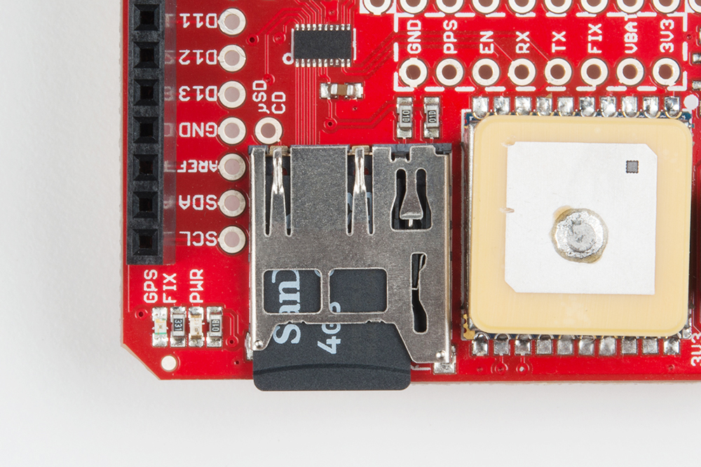
Once that's in place, upload and run! You can check the serial monitor for debugging data, or just trust that the logger is logging.
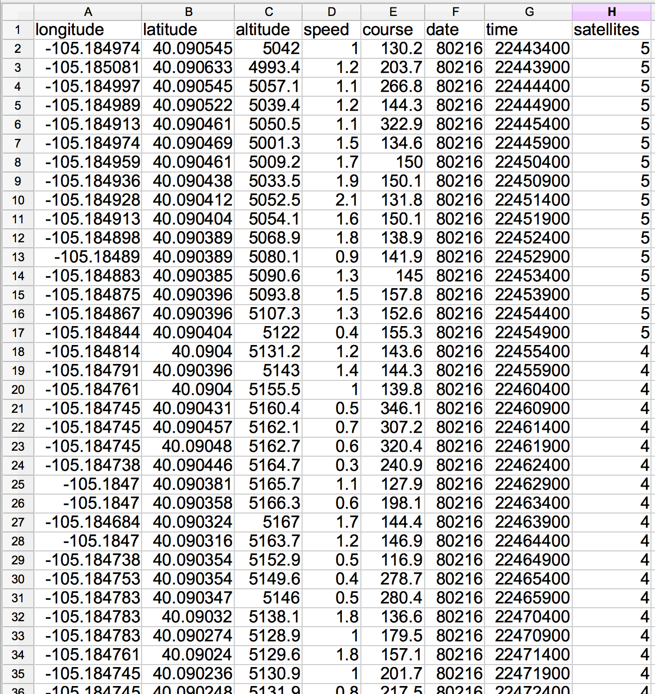
Once the GPS module gets a good fix, the Arduino will start logging longitude, latitude, altitude, speed, course, date, time, and the number of visible satellites into a CSV file. The data is set to log once every five seconds, but that's easily tunable if you need more or less data.
After letting it log for a bit, turn off your Arduino, load the SD card into your computer, and check for a GPSLOG###.CSV file. Open it up in a spreadsheet program, or just use a text editor to see what your Arduino logged.
Now really test the logger! Power your Arduino up with a battery (our 9V to Barrel Jack Adapter is handy for that)...
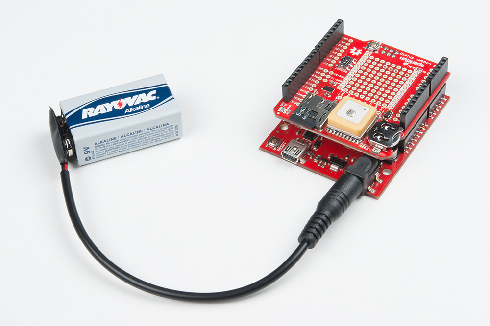
...and take your Arduino for a walk.
Resources and Going Further
Now that you've got your GPS Logger Shield up-and-running, what kind of position-tracking Arduino project are you going to make. Need a little more guidance, here are a few links you may find handy:
- SparkFun GPS Logger Shield Resources
- Arduino GPS Resources
If you need a little project inspiration, here's a SparkFun Live, where you can watch the full build of a GPS Speedometer:
Or check out some of these related SparkFun tutorials:
Copernicus II Hookup Guide
Alphanumeric GPS Wall Clock
CAN-BUS Shield Hookup Guide
Or check out this blog post for ideas.