Copernicus II Hookup Guide
 Toni_K
Copernicus II Overview
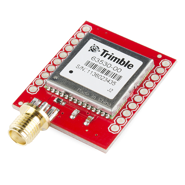
The Copernicus II GPS Module is a 12-channel receiver from Trimble. It has a small form factor, making it a great device for applications requiring precise GPS control. The DIP module board allows you to easily embed this into your projects by providing an easy to connect to interface.
The module supports NMEA, TSIP and TAIP protocols at 1 Hz. The board also is designed to interface with an SMA antenna.
The module runs at 3.3V and consumes around 40mA at 3.0V. For the TSIP protocol, the module's default baud rate is 38400 bps, while it defaults to 4800 bps for the NMEA protocol. These settings are configurable. The module is permanently set to 8 data bits, no parity, 1 stop bits and no flow control.
Suggested Reading
If you haven't worked with GPS before, or are unfamiliar with serial communication, you may want to read the following tutorials before continuing on with this module.
How to Solder: Through-Hole Soldering
Serial Communication
GPS Basics
How to Use a Breadboard
Hardware Hookup
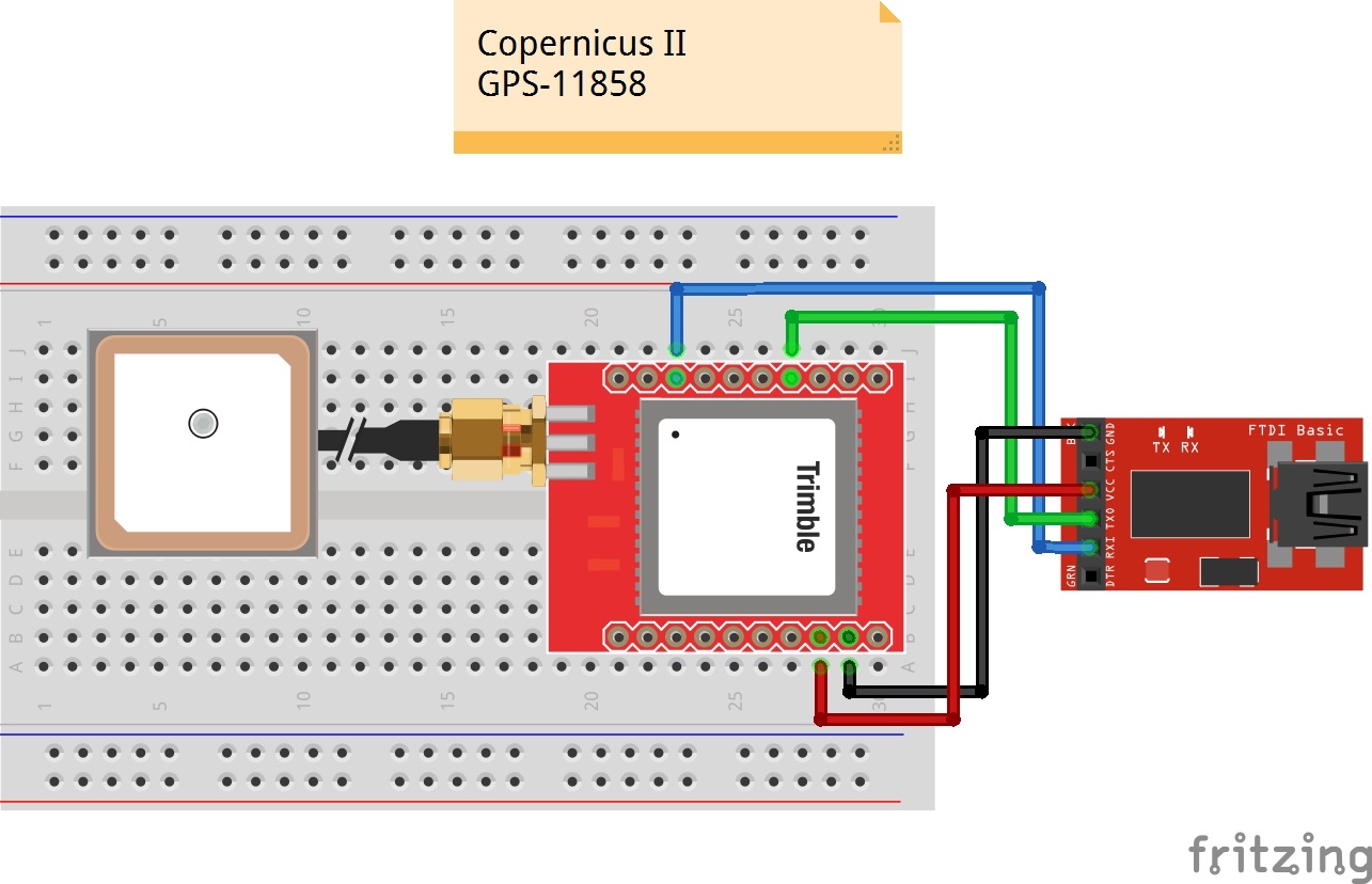
To get started communicating with the Copernicus II, you will need to connect four pins on the module: VCC, GND, TX-B, and RX-B.
For our example, we will be connecting the module to a terminal window on the computer using an 3.3V FTDI Basic Board, and will be using the GPS Antenna Embedded SMA.
Connections:
Copernicus II → 3.3V FTDI Basic
- VCC → 3.3V
- GND → GND
- TX-B → RXI
- RX-B → TXO
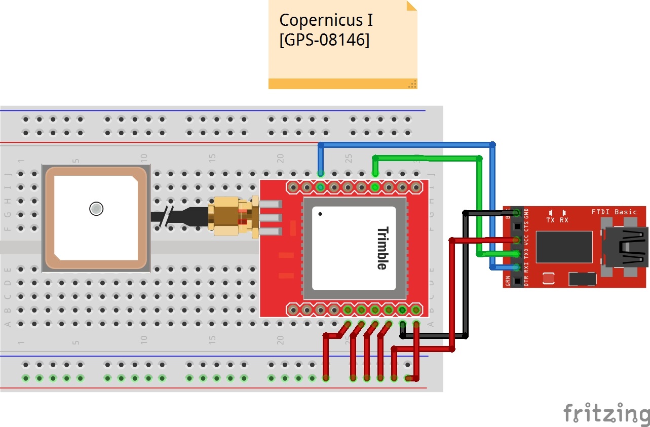
Take a look at the Fritzing diagram below showing the connections between the Copernicus II and the FTDI Basic based on the pin descriptions from the datasheet. In some cases, users needed to connect R2 to Vcc to operate but it should not be necessary.
Talking to the Module
Once you have your boards connected, open up your favorite serial terminal program and connect to the appropriate COM port for your FTDI Basic. The connection settings should be 4800 bps, 8 data bits, no parity, 1 stop bit, and no flow control.
If your module is hooked up properly and has a lock, you should see a scrolling output like this.
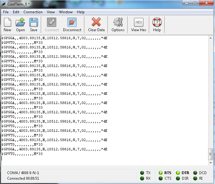
As you can see in the GPGGA output, the module is reading the position to be 4003.89135 N and 10512.58816 W, which happens to be SparkFun's headquarters. The module is also currently only seeing 2 satellites, and the location data being output is from the last value stored in the flash (shown by the GPS Quality Indicator of 7). The lack of additional data is due to testing this inside a large building like SparkFun where the signal fades in and out, so you should actually be getting more data from your module if testing near a window or outside with a clear view.
Talking to a Microcontroller
If you're looking to add GPS to your Arduino project using the Copernicus, we suggest you look into the Tiny GPS library. This library is great for parsing out the data that you want to use in your project such as time, altitude, position, etc. There are plenty of resources involving this library around the web. A quick search should yield plenty of examples. If you need a refresher on how to install an Arduino library, instructions can be found here.
Resources and Going Further
Now that you've gotten your module hooked up and can collect gps data from it, it's time to start integrating the module into your projects. Think about adding in gps navigation to an autonomous robot or creating a data logger for your car to track gas usage in different areas. Let us know what kind of cool projects you come up with, and leave us any feedback you might have on the tutorial. Check the files below for additional resources.
Resources
- Breakout Board Schematic (PDF)
- Breakout Board Eagle Files (ZIP)
- Copernicus II Datasheet
- GPSStudio Users Guide
- SparkFun GPS Tracking Tutorial
- GPS Tutorial by Michael Simpson
- Trimble Studio & Support Tools
- GitHub - Design files and archived library
Need some inspiration for your next project? Check out some of these related tutorials: