SparkFun RTK Reference Station Hookup Guide
 PaulZC
 Introduction
The RTK Reference Station from SparkFun is our most capable GNSS receiver and logger to date. It's your one stop shop for high precision geolocation, surveying and time reference needs. For basic users, it is incredibly easy to get up and running; for advanced users, the Reference Station is a flexible and powerful tool. We took everything we learned while developing our other RTK products, refined it and the Reference Station is the end result.
Is this just a RTK Facet in a metal box? Oh no! It is so much more... Sure, it is based on the same ESP32-WROOM processor and u-blox ZED-F9P multi-band GNSS module as the Facet. And it runs the same core firmware as the rest of the RTK product family. But there the similarities end. The Reference Station has 10/100 Mbps Ethernet connectivity provided by a WIZnet W5500 and it can be powered by Power-over-Ethernet (PoE) too. With just a few minutes of setup and survey-in, your Reference Station can be serving RTCM correction data to an NTRIP caster of your choice, all via Ethernet!
Need an affordable Network Time Protocol time server for your Ethernet network? We've got you covered. The Reference Station can act as a NTP server. It supports DHCP by default, but you can give it a fixed IP address if you want to. DNS, gateway and subnet mask are all configurable too.
The Reference Station gets a big speed boost too. The microSD card socket is connected via full 4-bit SDIO instead of the usual SPI, providing an order or magnitude improvement in read and write speeds. Similarly, the u-blox ZED-F9P GNSS module is connected via SPI instead of the usual I2C, also providing an order of magnitude improvement in data transfer speeds. Need to log RAWX and SFRBX at 20Hz? You can with the Reference Station!
Required Materials
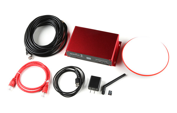
The RTK Reference Station comes with everything you need to get up and running. Our kit includes:
- Cased Reference Station
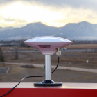
- L1/L2/L5 GNSS Surveying Antenna
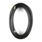
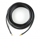
- Reinforced RG58 TNC-SMA Cable
- SMA WiFi / Bluetooth Antenna
- 32GB microSD Card
- USB-C Power Supply (wall charger)
- USB-C Cable
- Ethernet Cable
What else might you need? Well, it depends on where you are going to install and use your Reference Station. One obvious place would be up on your roof where your antenna will have the best view of the sky. In which case you will want some hardware to help mount the antenna:

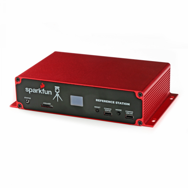
The Reference Station itself comes in a beautiful custom extruded aluminium enclosure, with machined end panels and matching stickers. The slotted flanges make it easy to install and secure the enclosure in many locations. But the enclosure only provides limited protection against the ingress of dust and water; it is IP42. So, if you are going to permanently install it up on the roof, you're going to need a suitable weatherproof box too. We found a good one - the Orbit 57095 - also available from Amazon - back when we put together our very first DIY GNSS Reference Station
How to Build a DIY GNSS Reference Station
If you want to keep your Reference Station warm and dry, it is equally at home on your desk, lab bench or in a server rack. You're still going to want to install the antenna outdoors though, so some extra SMA extension cables may be useful. The GNSS antenna connection is standard polarity. If you want to extend the ESP32 WiFi / BT antenna connection too, you need a Reverse Polarity (RP) cable for that. We have good quality RG58 extension cables available in the store:
Finally, if you're going to be logging a lot of data, you might want to stock up on 32GB microSD cards too. The Reference Station can log 'raw' GNSS data messages (RAWX and SFRBX) at 20Hz if desired. At that rate, you're logging about 50kB per second, 180MB per hour, or over 4GB per day! 32GB cards are the ones we recommend - as they come formatted as FAT32. The Reference Station does not support exFAT.

Suggested Reading
GNSS RTK is an incredible feat of engineering that has been made easy to use by powerful GNSS receivers such as the ZED-F9P by u-blox (the receiver inside RTK Reference Station). The process of setting up an RTK system will be covered in this tutorial but if you want to know more about RTK here are some good tutorials to brush up on:
What is GPS RTK?
Getting Started with U-Center for u-blox
GPS-RTK2 Hookup Guide
Setting up a Rover Base RTK System
How to Build a DIY GNSS Reference Station
Hardware Overview
The RTK Reference Station is a fully enclosed, preprogrammed device. There are very few things to worry about or configure but we will cover the basics.
Antenna Connections
Before connecting your Reference Station to a power source, you're going to want to connect it to a couple of antennas.
The rest of the RTK product family use a version of the ESP32-WROOM which has a built-in antenna. The Reference Station does it differently. You need to connect a 2.4GHz WiFi / BT antenna to the ESP32 SMA Reverse Polarity (RP) connector on the rear panel. We included one in the kit. Go ahead and screw it on there!
The GNSS antenna needs to be connected to the standard polarity UBLOX SMA connector. The TNC-SMA cable we included in the kit is of course perfect for the job. If you need a longer cable run, we have good quality RG58 cables available in the store.
microSD Card
Now is a good time to slot the microSD card into place. We included a 32GB card in the kit. Insert it gently into the microSD slot and give it a little push to lock it into place. It is a "push-push" socket. Push it again to release / eject the card.
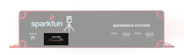
The Reference Station only supports cards formatted as FAT32, which is why we recommend 32GB cards. It does not support exFAT - and most 64GB cards come pre-formatted with exFAT.
If you need to re-format your card at any time, we recommend using the official SD Association Formatter.
Power Options
Unlike the rest of the RTK product family, the Reference Station has no internal battery. It is designed to be "always on". It will start operating as soon as it is connected to a power source. It can operate when powered by any or all of:
- ESP32 USB-C connector
- u-blox GNSS USB-C connector

- Rear USB-C power connector
- Power-over-Ethernet (36V - 57V)
- 5V and GND I/O screw terminals (5.5V DC Maximum)
We included a USB-C wall charger in the kit. Go ahead and plug it in to the rear USB-C power connector to power the system.
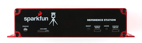
MODE Button

The Reference Station MODE button operates in almost the same way as the SETUP button on the other RTK products.
A single press brings up the mode menu. Press the button again to step through the available modes. Pause on the highlighted mode to select it and change to that mode.
The available modes are:
- BASE Mode
- ROVER Mode
- NTP Mode
- Cfg Eth Configure-Via-Ethernet Mode
- CfgWiFi Configure-Via-WiFi Mode
- E-Pair ESP NOW Pairing
The modes are discussed in a little more detail below and in much more detail in the RTK Product Manual.
BASE Mode is the default as it is the mode we think users will use the most - but you always surprise us with the novel ways you use our products!
A long press of the MODE button will make the Reference Station shut down. Once shut down, only a power cycle or a press of the RESET button will wake it again.
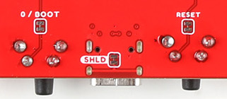
RESET Button
The RESET button is flush with the front sticker. You can still press it with your finger but it takes an assertive press, to prevent accidental resets.
You shouldn't need to press the RESET button often, if at all. Connecting to the ESP32 via USB and opening a serial console, or uploading new firmware, generates a reset automatically. But the RESET button is there if you need it.
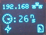
STATUS LED

The STATUS LED is used to indicate that all is well with the Reference Station. When lit, the BASE Mode has completed its survey-in.
CONFIG ESP32
The CONFIG ESP32 USB-C port provides direct access to the ESP32 Serial port / console. Connect to this from your computer and open a serial terminal at 115200 baud to see diagnostic messages from the RTK firmware. Tera Term is still a good choice for Windows users. Press any key to open the serial configuration menu.
The RTK product range is now able to update its own firmware Over-The-Air (OTA). But you can of course still upload your own code or our pre-compiled firmware binaries onto the ESP32 through this USB-C connection.
CONFIG UBLOX
The CONFIG UBLOX USB-C port provides direct access to the u-blox ZED-F9P GNSS module's USB port. You can use this port to connect to the module using u-blox u-center (we still recommend the original u-center over u-center2). You can also use it to update the ZED-F9P's firmware - either via u-center or using our own u-blox GNSS Firmware Update GUI.
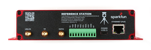
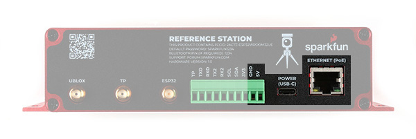
ETHERNET Port
The ETHERNET (PoE) RJ45 Mag Jack port on the rear of the Reference Station is - we hope - self explanatory. It is connected internally to the Power-over-Ethernet module and the WIZnet W5500 Ethernet transceiver. It supports 10/100Mbps communication with auto-negotiation. The mag jack has built-in Link and Activity LEDs. (You can disable these if needed by opening jumper links on the main PCB.) The Power-over-Ethernet module will operate from standard 36V to 57V PoE voltages. Choose a PoE Ethernet Switch that meets your needs. We have had good experiences with the TP-Link TL-SG1005P - available from many retailers including Amazon.
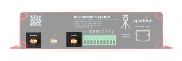
UBLOX SMA Connector
The L1/L2 GNSS antenna included in the kit should be connected to the UBLOX SMA connector using the provided SMA-TNC cable. The Reference Station provides 5V on this connector for an active antenna, instead of the usual 3.3V. The Reference Station also includes both short-circuit and open-circuit detection on this connection. New icons will flash on the OLED display if the antenna is not connected (open) or the cable develops a short.
TP SMA Connector
To try and make the Reference Station more lab-friendly, we connected the ZED-F9P's TP (Timing Pulse, Pulse-Per-Second) pin to a dedicated OpAmp circuit and SMA connector. The default output voltage is 3.3V, but you can select 5V by opening a jumper link on the main PCB. It is not intended to replace your lab signal generator, but it works well up to 100kHz. The unprocessed TP / PPS 3.3V signal is also available on the TP I/O screw terminal. Please see the Product Manual for more details.
ESP32 SMA Connector
The ESP32 WROOM module's u.FL connector is connected to a robust Reverse Polarity (RP) SMA connector. You can screw the provided WiFi / BT antenna directly onto this connector, just like you would with any broadband router. If you want to mount the antenna further away, we have good quality RG58 RP extension cables available in the store.
I/O Screw Terminals
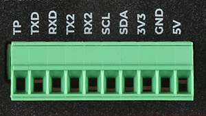
The Reference Station is equipped with a robust 10-way 3.5mm Input / Output screw terminal header. This provides access to the power rails and I/O signals:
- TP : u-blox ZED-F9P GNSS module Timing Pulse (Pulse Per Second): 3.3V OUTPUT
- TXD : ESP32 pin 17 Serial1 (UART) transmit: 3.3V OUTPUT
- The current version of the RTK firmware does not use this pin
- RXD : ESP32 pin 16 Serial1 (UART) receive: 3.3V INPUT
- The current version of the RTK firmware does not use this pin
- TX2 : u-blox ZED-F9P UART2 transmit: 3.3V OUTPUT
- You can connect this pin to a radio module to provide correction data to other Rovers
- RX2 : u-blox ZED-F9P UART2 receive: 3.3V INPUT
- You can connect this pin to a radio module to use correction data provided by another Base
- SCL : ESP32 I2C (Wire / Qwiic) bus clock : 3.3V
- A pull-up is provided on the main PCB. This can be disabled by opening a jumper link
- SDA : ESP32 I2C (Wire / Qwiic) bus data : 3.3V
- A pull-up is provided on the main PCB. This can be disabled by opening a jumper link
- 3V3 : 3.3V power OUTPUT
- This is the internal switched power rail used by the microSD card and WIZnet W5500
- It is enabled by ESP32 pin 32 (PWREN)
- It is disabled when the ESP32 is in reset
- You could use it to power an external radio module or a Qwiic / I2C device
- GND : power GND / 0V
- 5V : 5V power INPUT
- This pin can be used to power the Reference Station from a separate 5V power source
- The maximum voltage is 5.5V DC
Hardware Overview - Advanced Features
Like most SparkFun products, the RTK Reference Station is completely open source. We're happy to share the full schematic for the main PCB, the Eagle CAD files and the full source code for the firmware. The Reference Station is intended to be another hacker's paradise!
Taking the Reference Station apart is really easy:
- Disconnect all cables
- Unplug the green 10-way 3.5mm I/O connector
- This makes it easy to remove the main PCB from the enclosure
- The connector is a firm fit. You may need to rock it from side to side as you unplug it
- Unscrew the four screws holding the front panel in place
- We recommend removing the front panel first, so you can unplug the OLED display
- Remove the front panel
- Unplug the OLED Qwiic cable
- Slide out the main PCB
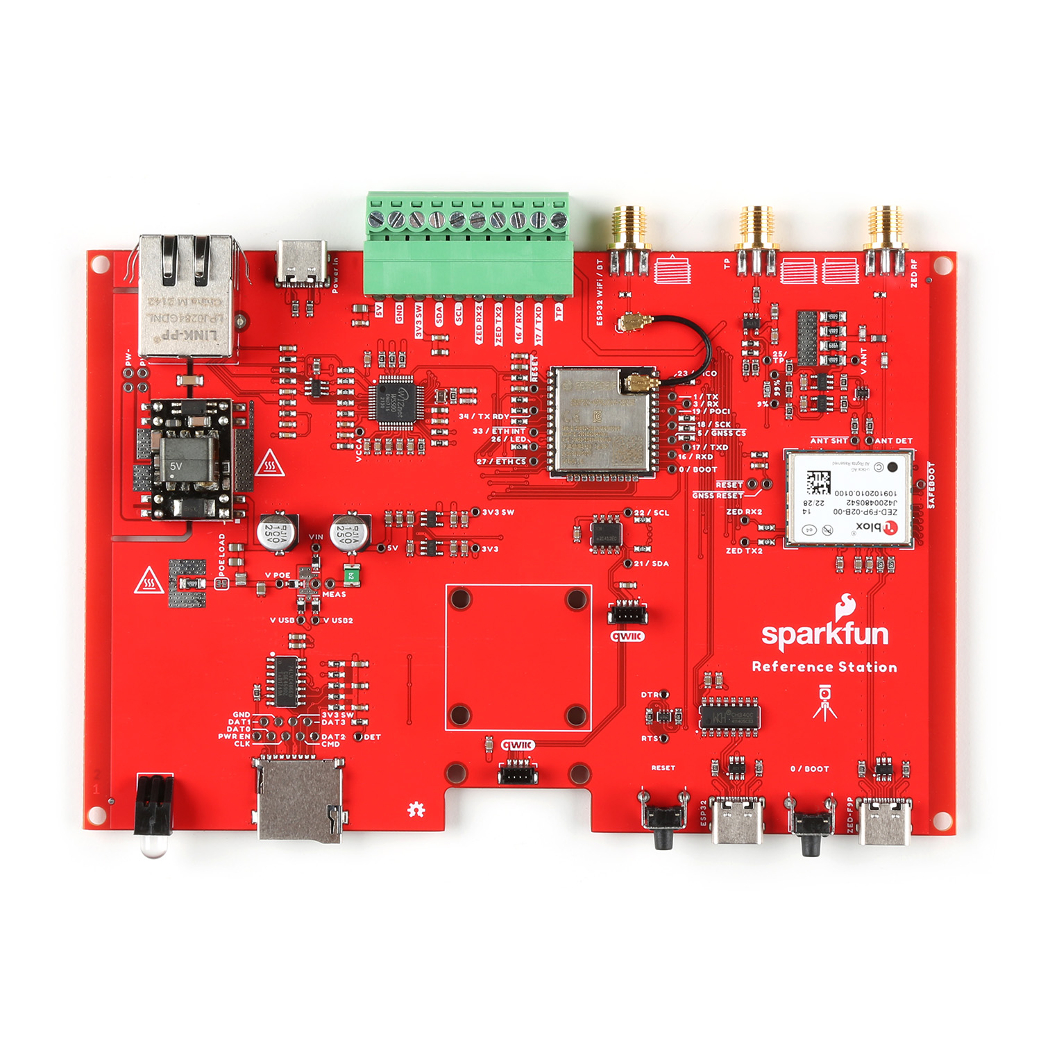
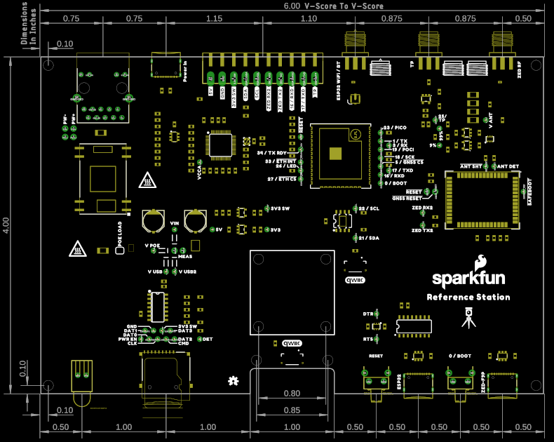
Let's walk you through the main components on the PCB:
ESP32-WROOM
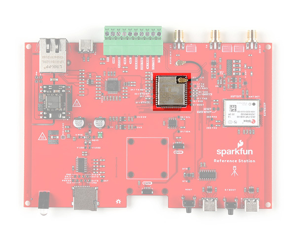
Like the other members of the RTK product family, the RTK Reference Station uses the excellent ESP32-WROOM microcontroller. The only difference here is that we use a version with a built-in u.FL antenna connection. We use a small u.FL cable to connect the ESP32 to the external RP SMA antenna connector.
u-blox ZED-F9P GNSS
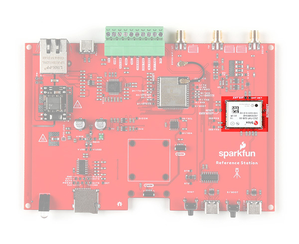
Like most of the RTK product family, the RTK Reference Station uses the excellent ZED-F9P multi-band GNSS module, made by u-blox in Switzerland. We keep using this module because it is phenomenal and we haven't found anything better. The only difference here is that it is connected via SPI, instead of the usual I2C. This provides an order of magnitude improvement in the data transfer speeds.
WIZnet W5500 Ethernet Transceiver
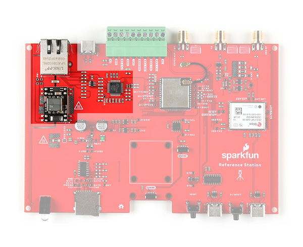
The WIZnet W5500 has been around for years, but it still takes some beating for 10/100Mbps Ethernet applications. We've paired it with a high quality Power-over-Ethernet (PoE) module and shielded RJ45 connector ("mag jack").
Qwiic 1"x1" Footprint
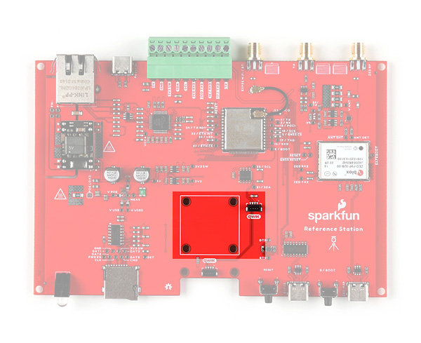
Did we forget to include something? Absolutely not! But we did say that the Reference Station is a hacker's paradise. We've included the 1" x 1" footprint of our standard Qwiic (I2C) sensor boards just in case you want to add your own Inertial Measurement Unit, Pressure Humidity Temperature sensor, battery-backed Real Time Clock or anything else you need for your project. There's a vacant Qwiic connector right there too!
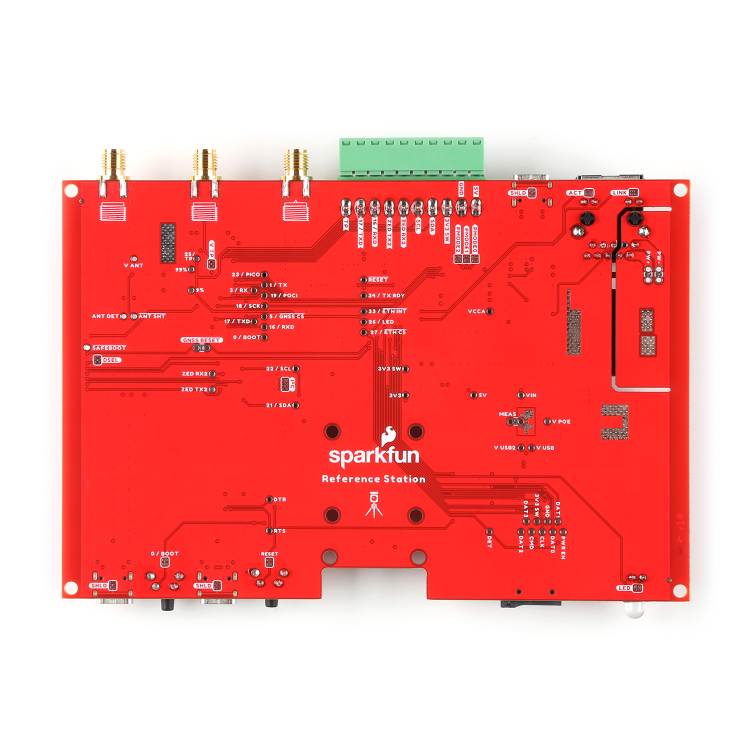
Jumper Links
Like most SparkFun products, the RTK Reference Station PCB has several split-pad jumper links on it, which allow you to configure the board in different ways.
Need to disable all of the LEDs? Not a problem. You will find jumper links for the Link, Activity and Status LEDs. Open them up and leave the OLED display disconnected to blackout your Reference Station.


Need to change the WIZnet W5500 mode? You can do that by configuring the three PMODE jumpers. PMODE0, 1 and 2 are pulled high by default. You can pull them low by soldering the jumpers closed.

There may be times when you want to prevent anyone from pressing the RESET or MODE buttons. There are jumper links for those too. Open them to isolate the two buttons; the ESP32 can then still be reset via the USB-C port and CH340 interface if needed.
To make the Reference Station more lab friendly, we included a SMA connection for the ZED-F9P time pulse (Pulse-Per-Second). The SMA signal is 3.3V by default, but you can change it to 5V by opening the VTP jumper.

Modus Operandi
The following is a brief summary of the Reference Station's modes of operation. Please consult the RTK Product Manual for much more detail.
- BASE Mode
- This is the default mode as it is the mode we think most users will want to use - but you always surprise us with the novel ways you use our products!
- The Reference Station will perform a short 1-2 minute "survey-in" to establish the approximate position of the antenna (~1m accuracy).
- It will then start generating RTCM correction data and - once configured - can send it to an NTRIP Caster over Ethernet.
- The RTCM data will also be output as 3.3V Serial (UART) data on the ZED-F9P TX2 I/O screw connection on the rear panel. You can connect a Radio transceiver to that pin if desired.
- You can establish the antenna position more accurately by collecting 'raw' satellite data for ~24 hours and post-processing it. You can find full instructions in the Product Manual.
- ROVER Mode
- The Reference Station can of course also be used as a RTK Rover.
- In Rover mode, the antenna position and other data is logged to microSD card.
- RTCM correction data can be received over Ethernet from a NTRIP Caster - once configured - and used to achieve an accuracy of ~1.4cm under good conditions.
- Use Rover mode to collect the 'raw' satellite data to establish your antenna's position accurately for Base mode.
- NTP Mode
- The Reference Station can also act as a Network Time Protocol Server - servicing NTP requests over Ethernet.
- The firmware defaults to using DHCP to obtain an IP Address. But you can also configure it to use a fixed IP Address and can define the DNS, Gateway and Subnet Mask too.
- Because NTP is unique to the Reference Station, we talk about it a bit more in the next section.
- CONFIGURE VIA ETHERNET Mode
- Abbreviated as "Cfg Eth", Configure-Via-Ethernet mode is a dedicated mode where the Reference Station can be configured via a web page over Ethernet.
- This mode requires exclusive access to the WIZnet W5500 chip and the SPI bus and so the Reference Station actually reboots when this mode is selected.
- When leaving this mode - either by exiting the web page or by pressing the Mode button - the Reference Station will reboot again into Base, Rover or NTP mode. The new mode is selected by the small drop-down box on the System tab.
- CONFIGURE VIA WIFI Mode
- Abbreviated as "CfgWiFi", Configure-Via-WiFi mode is another dedicated mode where the Reference Station can be configured via a web page over WiFi.
- By default, the Reference Station will appear as a WiFi Hot Spot / Access Point - but it can be configured to connect to your preferred WiFi network too.
- The Reference Station will reboot when leaving this mode - to apply any changes made.
- ESP NOW Mode
- Abbreviated as "E-Pair", ESP NOW is a way of linking two ESP32 processors via WiFi so that they can communicate with each other, line of sight up to approximately 250m
- The ESP NOW link allows a base to share correction data with a single rover
- More details are provided in the Product Manual
NTP
Network Time Protocol has been around since 1985. It is a simple way for computers to synchronize their clocks with each other, allowing the network latency (delay) to be subtracted:
- A client sends a NTP request (packet) to the chosen or designated server
- The request contains the client's current clock time - for identification
- The server logs the time the client's request arrived and then sends a reply containing:
- The client's clock time - for identification
- The server's clock time - when the request arrived at the server
- The server's clock time - when the reply is sent
- The time the server's clock was last synchronized - providing the age of the synchronization
- The client logs the time the reply is received - using its own clock
When the client receives the reply, it can deduce the total round-trip delay which is the sum of:
- How long the request took to reach the server
- How long the server took to construct the reply
- How long the reply took to reach the client
This exchange is repeated typically five times, before the client synchronizes its clock to the server's clock, subtracting the latency (delay) introduced by the network.
Having your own NTP server on your network allows tighter clock synchronization as the network latency is minimized.
The Reference Station can be placed into its dedicated NTP mode, by pressing the MODE button until NTP is highlighted in the display and pausing there.
The Reference Station will first synchronize its Real Time Clock (RTC) using the very accurate time provided by the u-blox GNSS module. The module's Time Pulse (Pulse-Per-Second) signal is connect to the ESP32 as an interrupt. The ESP32's RTC is synchronized to Universal Time Coordinate (UTC) on the rising edge of the TP signal using the time contained in the UBX-TIM-TP message.
The WIZnet W5500 interrupt signal is also connected to the ESP32, allowing the ESP32 to accurately log when each NTP request arrives.
The Reference Station will respond to each NTP request within a few 10's of milliseconds.
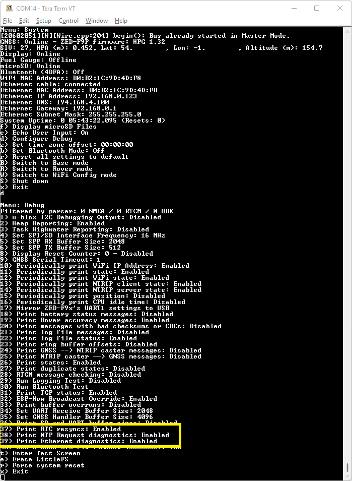
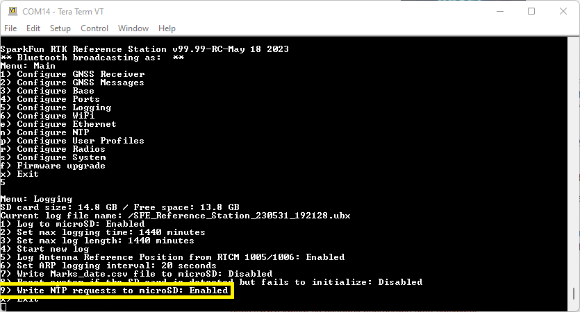
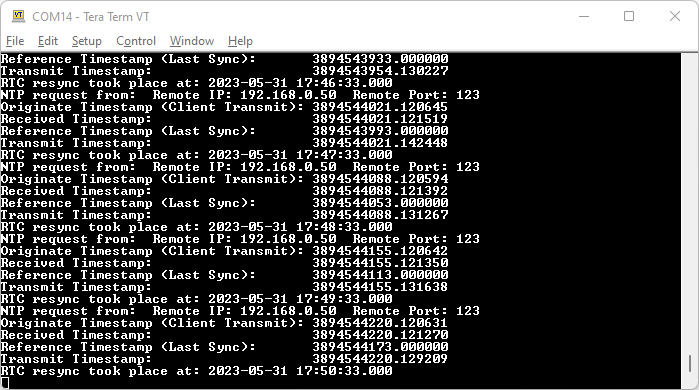
If desired, you can log all NTP requests to a file on the microSD card, and/or print them as diagnostic messages. The log and messages contain the NTP timing information and the IP Address and port of the Client.
We have been using Meinberg NTP to synchronize Windows PCs to the Reference Station - please see the Product Manual for more details.
NTP uses its own epoch - midnight January 1st 1900. This is different to the standard Unix epoch - midnight January 1st 1970 - and the GPS epoch - midnight January 6th 1980. The times shown in the log and diagnostic messages use the NTP epoch. You can use online calculators to convert between the different epochs:
System Configuration
The SparkFun RTK products are versatile GNSS receivers straight out of the box and can be used with little or no configuration. Additionally, the line of RTK products from SparkFun are immensely configurable. Please see the SparkFun RTK Product Manual for detailed descriptions of all the available features on the RTK products.
Tried and Tested Configurations
The RTK Reference Station does so much that it is difficult for us to methodically test everything it is capable of.
We also need to be honest and say that the RTK firmware uses almost all of the RAM available on the ESP32-WROOM, especially on the Reference Station where we need to reserve additional RAM for the SDIO (SD_MMC) microSD interface and to buffer the high-bandwidth SPI data from the GNSS module. The Reference Station is slightly compromised as we do not have enough RAM to run WiFi, Bluetooth, SDIO and Ethernet at the same time, while pulling high message rate data from the GNSS.
The list below contains configurations that we have tried and tested, and have found to work well. But you will notice some missing configurations - like supporting TCP Client and Server over WiFi - for the reason outlined above.
- Base Mode: Survey-In or Fixed Position; NTRIP Server enabled - corrections are sent to the NTRIP Caster via Ethernet
- Tested with rtk2go.com
- A measurement rate of 1Hz is recommended (the default is 4Hz)
- Base Mode: Configuration via Bluetooth
- Tested with Serial Bluetooth Terminal on Android
- Rover Mode: NTRIP Client enabled - corrections received from the NTRIP Caster via Ethernet
- Tested with rtk2go.com
- A measurement rate of 1Hz is recommended (the default is 4Hz)
- Rover Mode: NTRIP Client with location display on (e.g.) SW Maps
- Tested using SW Maps on Android
- SW Maps connected to rtk2go.com NTRIP Server / Caster via WiFi and providing corrections to the Reference Station via Bluetooth
- Real-time display of Reference Station location and position accuracy via Bluetooth
- Rover Mode: Configuration via Bluetooth
- Tested with Serial Bluetooth Terminal on Android
- NTP Mode
- Tested with Raspberry Pi (with ntp and ntpq) and Windows PC (with Meinberg NTP - see the Product Manual for details)
- Excellent agreement with NTP Pool servers
- Configure-Via-Ethernet Mode
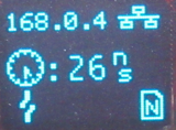
- Reference Station is booted into a dedicated mode to allow configuration via a web page over Ethernet
- The Ethernet IP address is displayed on the OLED display
- Supports microSD file upload / download and deletion
- Configure-Via-WiFi Mode
- Identical to the other RTK products
- Both Access Point (Hotspot) and network modes are supported
- TCP Client: provision of NMEA and / or UBX GNSS messages to an external TCP Server via Ethernet
- Configured via the Ethernet Menu / configuration tab
- NMEA and / or UBX messages can be sent to an external TCP server (to its IP address or URL)
- Firmware Update: update Over-The-Air via WiFi
Things Which Work - If You Are Careful
As we mentioned above, the Reference Station RTK firmware uses almost all of the ESP32-WROOM's RAM. Unfortunately this means you can not have both WiFi and Bluetooth running simultaneously for example. It also complicates things if you use additional RAM by: using the ESP-NOW radio link; or allocate extra RAM for high rate GNSS message storage.
The following configurations do work, but you do need to proceed carefully:
- ESP-NOW:
- The E-Pair Mode does work, you can use the ESP-NOW radio link to send correction data from a Reference Station Base to a RTK Rover, but only if Bluetooth is disabled
- Disable Bluetooth via the System Menu. Select "b" twice to: first select BLE mode; and then to disable Bluetooth completely
- Restart the system using the System Menu \ Debug Menu: enter "s" followed by "d" followed by "r" to restart the Reference Station. This ensures the RAM used by Bluetooth is released
- Select the E-Pair option by pressing the MODE button until "E-Pair" is displayed
- Pair the Reference Station Base with an RTK Rover and the Rover will achieve RTK-Fix
- Please see the Product Manual for more details
- RXM-RAWX and RXM-SFRBX Logging at 20Hz
- The Reference Station can log RXM-RAWX and RXM-SFRBX at 20Hz, but only if you increase the size of the GNSS Handler Buffer
- Start by disabling Bluetooth as described above
- Open the System Menu \ Debug Menu and select option 35. Increase the GNSS Handler Buffer to 16384 - 65535 bytes for best results
- Restart the Reference Station and then use the GNSS Receiver Menu to increase the measurement rate to 20Hz
- For best results, use a freshly-formatted microSD card. The card write speed can reduce dramatically if it contains multiple files
Unsupported Configurations
The following is a summary of the configurations which the Reference Station does not currently support (as of firmware 3.4):
- Base Mode: Survey-In or Fixed Position; NTRIP Server enabled - corrections sent via WiFi
- Rover Mode: NTRIP Client enabled - corrections received via WiFi
- Firmware Update: update via Ethernet
Firmware Updates and Customization
The RTK Reference Station is open source hardware meaning you have total access to the firmware and hardware.
From time to time SparkFun will release new firmware for the RTK product line to add and improve functionality. We've made updating the firmware as easy as possible. Please see Updating RTK Firmware for a step by step tutorial.
Troubleshooting
If you need technical assistance and more information on a product that is not working as you expected, we recommend heading on over to the SparkFun Technical Assistance page for some initial troubleshooting.
If you don't find what you need there, the SparkFun Forums are a great place to find and ask for help. The best place to ask about the RTK product range is the Global Positioning Forum. If this is your first visit, you'll need to create a Forum Account to search product forums and post questions.
Resources and Going Further
We hope you enjoy using the RTK Reference Station as much as we have!
Here are the pertinent technical documents for the RTK Reference Station:
- RTK Product Manual
- Hardware GitHub Repo (contains the open source hardware electronics and enclosure design)
- Schematic
- Case Dimensions
- PCB Dimensions
- ZED-F9P GNSS Receiver Datasheet
- MAX17048 Fuel Gauge IC
- ATECC608A Crypto Co-processor Datasheet Summary
- WIZnet W5500 Datasheet
- Ag9900M PoE Module Datasheet
- RJ45 Ethernet Mag Jack Datasheet
Here are the links to the firmware, update tools and stand-alone code examples:
- RTK Firmware Binaries
- RTK Firmware Uploader
- RTK Firmware Source (contains the firmware that runs SparkFun RTK products)
- u-blox GNSS Firmware Update GUI (Windows only. Sorry!)
- Arduino Examples / Test Sketches
Check out these additional tutorials for your perusal: