ESP8266 WiFi Shield Hookup Guide
 jimblom
 Introduction
The ESP8266 is a popular, inexpensive WiFi/microcontroller system-on-chip (SoC). Although it can be programmed like any microcontroller, the ESP8266's popularity was gained as a simple, serially-controlled WiFi gateway. Using an AT command set, any microcontroller with a UART can use the ESP8266 to connect to WiFi networks, and interact with the rest of the Internet world over TCP or UDP. It's an easy (and cheap!) way to get your Arduino on the Internet!
There are a variety of designs based around the ESP8266, including tiny, modular boards and more accessible development boards like the SparkFun ESP8266 Thing. The ESP8266 WiFi Shield finds a middle ground between the Module and the Thing -- it comes pre-flashed with an AT-command firmware, so it can be controlled by any UART, but it also breaks out and provides command access to all of the ESP8266's I/O. It comes in the familiar Arduino Shield shape, and should work with any similarly-sized Arduino-compatible development board out there.
Whether you want an introduction to the ESP8266 -- without leaving the comfortable hardware confines of your Arduino -- or you just have a back-stock of Arduino's that need an inexpensive gateway to the Internet, the ESP8266 WiFi Shield may meet your needs.
Covered In this Tutorial
This tutorial details the hardware and firmware design behind the ESP8266 WiFi Shield. It also explains how to use the Shield with an Arduino-compatible development board and the Arduino IDE. The guide is broken down into a few sections, which you can navigate around using the bar on the right. Those sections include:
- Hardware Overview -- The main components and hardware features of the Shield are covered in this section.
- AT Firmware Overview -- Documentation links, and a quick introduction to the firmware running on the ESP8266 WiFi Shield.
- Hardware Assembly -- Tips and tricks for assembling your WiFi Shield.
- Installing the ESP8266 AT Library -- Everything you should need to install the ESP8266 AT Arduino library.
- Using the ESP8266 AT Library -- Pointers to help get you started writing an ESP8266 Arduino sketch of your own.
- (Re-)Programming the ESP8266 -- Take the ESP8266 WiFi Shield further by loading your own code onto the shield! The ESP8266 is even Arduino compatible.
Required Materials
The ESP8266 Shield surrounds the WiFi SoC with everything it should need to operate and connect to a WiFi network. All you need to add to it are headers, some solder, and an Arduino. Here are a list of parts we use in the tutorial, in case you want to follow along:

Instead of the RedBoard, you should be able to use almost any other Arduino-compatible development board -- the Uno or Leonardo for example.
You'll also need a set of soldering tools, if you don't already have them. A simple iron and some solder should really be all you need.
Suggested Reading
Before delving headlong into this tutorial, there are a few concepts you should be familiar with. Check out these related tutorials, if their content sounds foreign to you:
- What is an Arduino? -- What is this 'Arduino' thing anyway?
- Arduino Shields -- All things Arduino Shields. What they are and how to assemble them.
- Serial Communication -- Asynchronous serial communication concepts: packets, signal levels, baud rates, UARTs and more!
- How to Solder - Through-hole Soldering -- Are you new to electronics and soldering? Have you soldered before but need a refresher? Do you solder all day everyday but still feel you could use a few tips and tricks? This tutorial with cover everything you need to know about through-hole soldering.
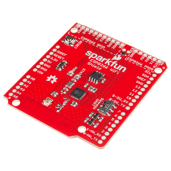
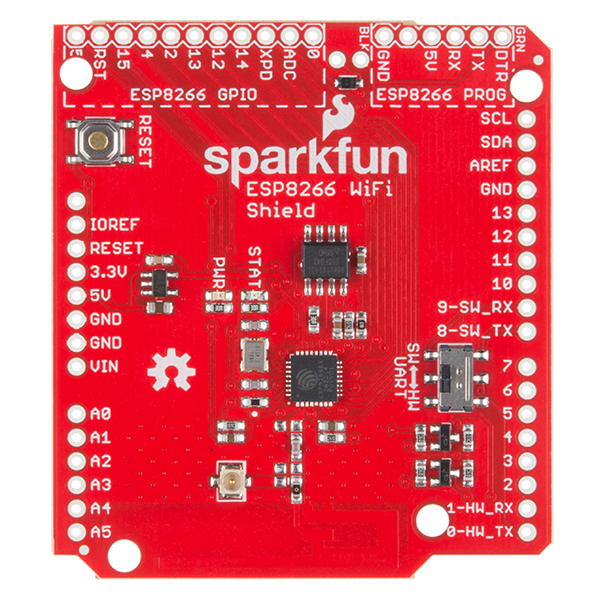
Hardware Overview
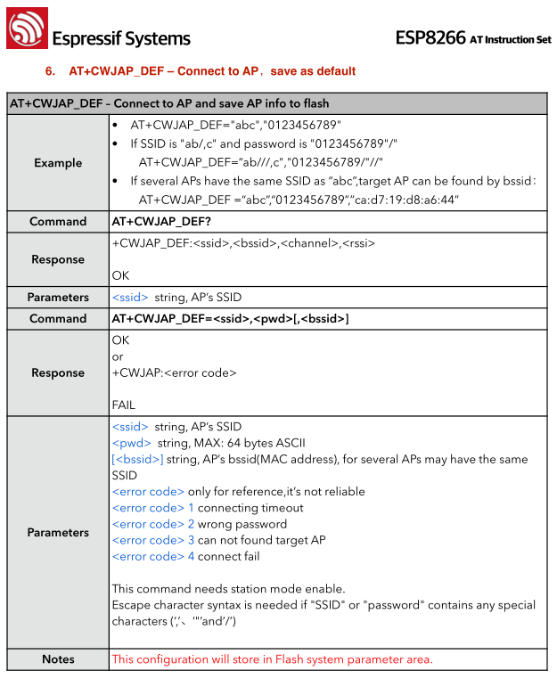
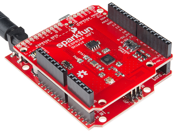
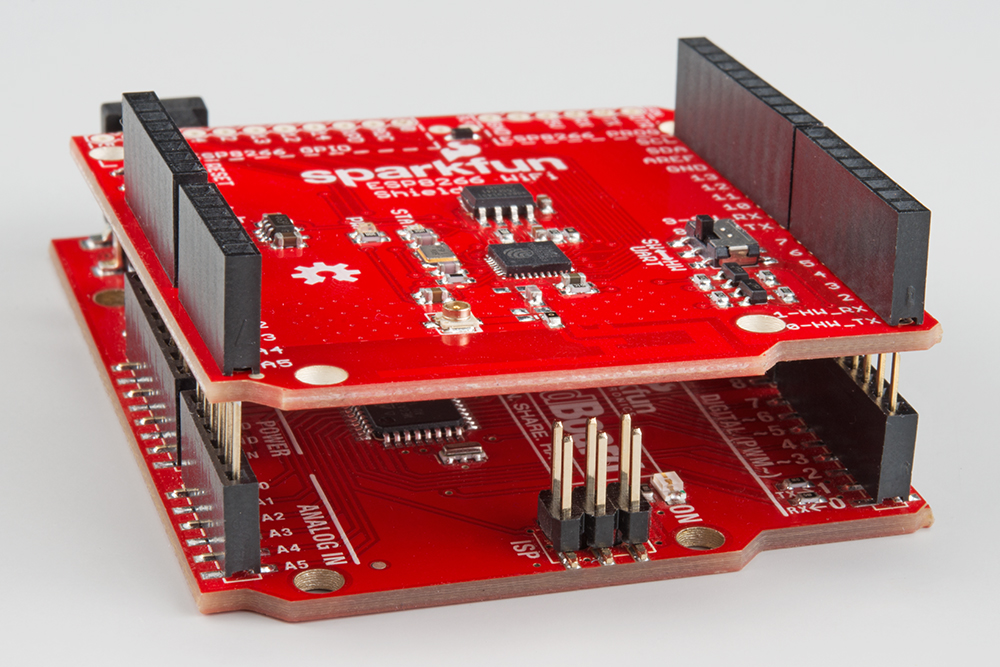
This section covers the hardware features of the ESP8266 WiFi Shield. Most of the board's action is on the top side, which should look a little something like this:
There are a couple features you should be familiar with, before equipping the Shield with headers and plopping it on you Arduino.
Serial Ports -- Selectable and Level Shifted
The ESP8266 WiFi Shield features selectable serial lines, which route the RX and TX signals to either the Arduino's devoted hardware serial port (on pins 0 and 1), or a software serial port on pins 8 and 9. The active port is selected by the on-board switch.
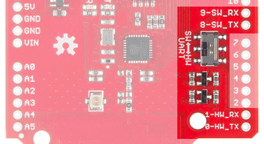
The switch's positions are labeled "SW" and "HW" for "software" and "hardware"; they should be intuitive -- slide towards the hardware port for "HW" and towards pins 8 and 9 for "SW".
The ESP8266's default baud rate is set to 9600, so, for most sketches, software serial works fine, and allows the hardware port to be used for debugging. We recommend keeping this switch set to "SW" unless you need those pins for something else, or just have to use hardware serial.
It's also important to note that the ESP8266's maximum input voltage is about 3.3V. To avoid any voltage conflict between a 5V Arduino and the ESP8266, the RX and TX signals are level shifted between 5V and 3.3V.
Arduino Reset Button
The shield's reset button is tied only to the Arduino. Pressing and releasing the button will restart the Arduino, running it's sketch from the top of the setup() function.
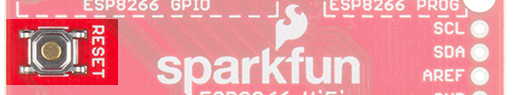
Pressing the reset button will have no immediate effect on the ESP8266.
LED Indicators
The WiFi Shield includes two LED indicators: a simple red power indicator and a blue "status" LED. The red power LED should illuminate whenever power is being delivered from the Arduino to the ESP8266 Shield. If you need to debug anything, checking for this LED should be your first step.
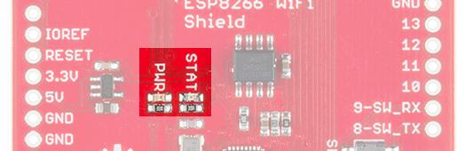
The blue status LED is tied into the firmware of the ESP8266. It'll blink, be solid, or turn off depending on which state it's in.
| LED State | ESP8266 State |
|---|---|
| Off | WiFi disconnected. Not configured. |
| Blinking | Station mode: ESP8266 attempting to connect to access point. AP mode: ESP8266 waiting for incoming connections |
| On | Station mode: ESP8266 connected to access point. AP mode: Devices connected to ESP8266 AP. |
The status LED is tied to GPIO 5 of the ESP8266.
ESP8266 GPIO and Programming Ports
The ESP8266 is a much more than a simple serial-to-WiFi gateway. It's has almost a dozen I/O that can be configured as digital inputs or outputs -- it even has a (relatively limited) ADC! These GPIO are all broken out towards the top-left side of the shield.
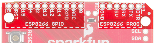
The shield's firmware is equipped with custom commands, which allow your Arduino to set, write, and read to these pins. More on that later.
The ESP8266 WiFi Shield can also be repurposed and reprogrammed through the programming port. Whether you want to add AT commands of your own, or flash custom firmware on the ESP8266, this port may come in very handy later on.
The pinout of the programming port matches our FTDI Basic breakouts. Solder on some male headers, and mate the two boards together to set up the programming interface. More on that later too!
AT Firmware Overview
While the hardware is obviously important, what really makes the WiFi Shield play nicely with an Arduino is its serial-based AT command-set firmware.
The ESP8266 WiFi Shield ships with Espressif's (the manufacturer of the ESP8266) latest release of their AT command set firmware. We've tweaked the base firmware to add support for the status LED and serial control of the ESP8266's unused I/O. Our firmware is as open source as can be (some of Espressif's source is only available as blobs) -- you can check it out in our ESP8266 WiFi Shield GitHub repository.
Using the AT Command Set
In later parts of this tutorial, we'll introduce an Arduino library, which handles all of this "AT" stuff for you. But it doesn't hurt to at least familiarize yourself with the commands used to configure the ESP8266.
For the full list of the ESP8266's AT commands check out this document. There are a variety of commands, which configure everything from access-point names/passwords, to TCP connections, to the device's baud rate.
If you're manually entering these commands, keep in mind that the end of each command should be signaled by a carriage return then line feed ("\r\n").
As an example exercise, here are a series of commands you might type to connect a WiFi access point and get your IP address:
> AT+CWOMDE=1
    OK
> AT+CWJAP="MySSID","MyPSK"
    WIFI CONNECTED
    WIFI GOT IP
    OK
> AT+CIFSR
    +CIFSR:STAIP,"192.168.0.101"
    +CIFSR:STAMAC,"18:fe:34:9d:b7:d9"
Custom GPIO Commands
We've taken Espressif's AT command firmware and added a few additional functions which give you control over the ESP8266's unused digital GPIO. In all, there are 9 GPIO to be digitally controlled: 0, 2, 4, 5, 12, 13, 14, 15, and 16 (XPD).
The custom commands allow you to set a pin to input or output (or input with pullup resistor), digitally write high or low, or read the pin's state:
| Function | Command | Example | Notes |
|---|---|---|---|
| Pin Mode | AT+PINMODE=<pin>,<mode> | AT+PINMODE=5,o | Mode:
|
| Digital Write | AT+PINWRITE=<pin>,<state> | AT+PINWRITE=5,h | State:
|
| Digital Read | AT+PINREAD=<pin> | AT+PINREAD=0 | Response: 0 or 1 for LOW or HIGH. |
Hardware Assembly
Before you can use the ESP8266 Shield, you'll need to solder a few headers in so it can interface with your Arduino.
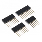
Stackable headers are always a good option for shields, especially if you plan on stacking more shields or plugging in jumper wires.
You can also opt for the more form-factor-friendly male headers, if stacking isn't as important to you.
Depending on how you'll use the shield, you can also solder headers into the ESP8266 GPIO and program headers. The programming header can interfere with the bigger USB-B connectors on Arduino Uno's, so keep their clearance in mind when you're soldering them in.
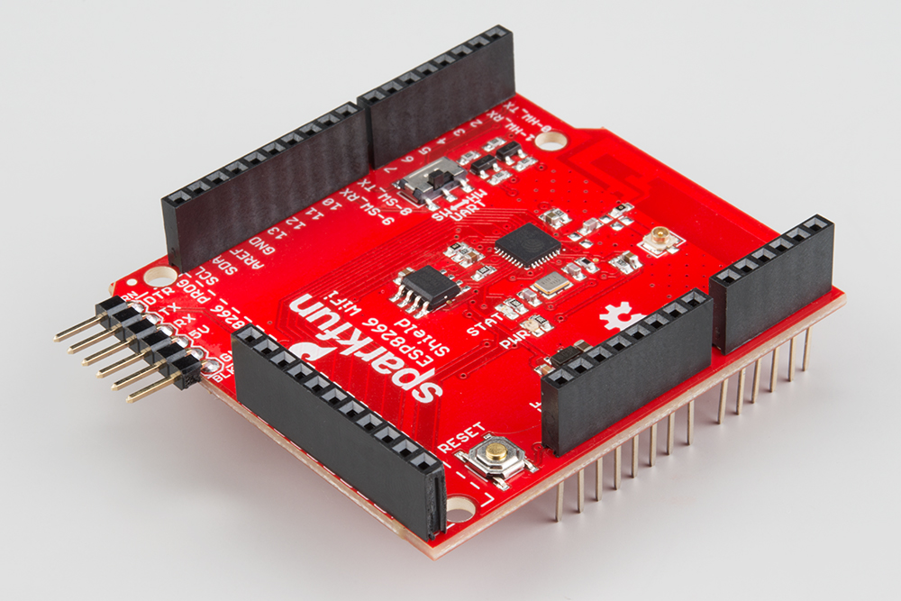
Female headers can be a good choice for the GPIO header, while right angle male headers make it easy to interface the programming headers with an FTDI breakout.
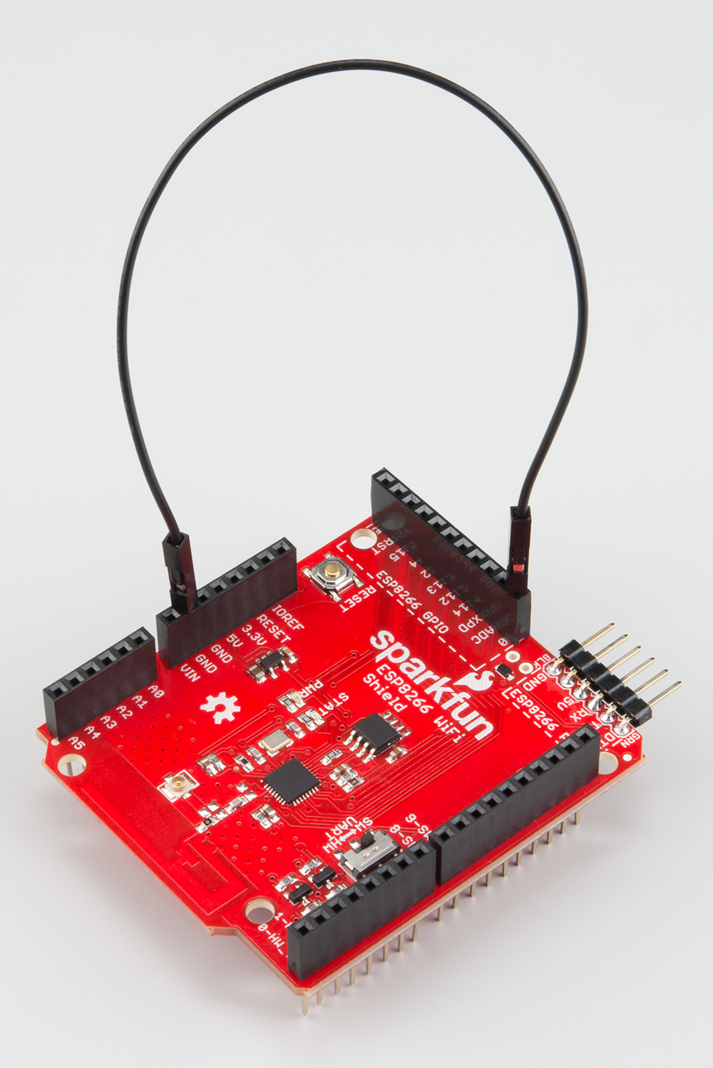
Antenna Clearance
Unfortunately, the ESP8266 WiFi Shield's printed PCB antenna can potentially run into interference problems with Arduino ISP headers. After seating the shield on your Arduino, you may want to slightly nudge the shield up, to avoid bumping the board against the 2x3 ISP header.
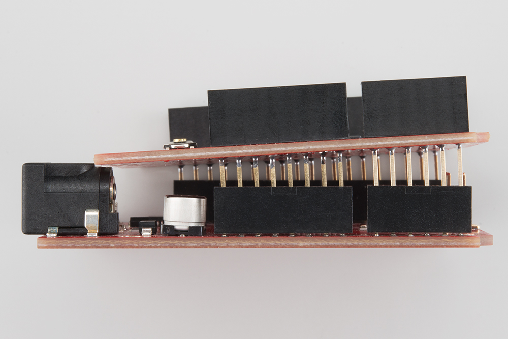
The header can interfere with the Shield's WiFi signal, and lead to lower-than-expected signal sensitivity. If your shield is having trouble connecting to a network, make sure there's some clearance here.
Installing the ESP8266 AT Library
Let's get to programming! To make interfacing with the shield's AT command set as painless as possible, we've written a simple Arduino library. You can get the library from our GitHub repository, or download it by clicking the button below.
We recommend using the latest version of Arduino with this library (currently 1.6.5). For help installing the library check out our Installing an Arduino Library tutorial.
Run the ESP8266_Shield_Demo Example
The SparkFun ESP8266 AT library includes a handful of example sketches, they demonstrate everything from connecting to an access point, to serving up a webpage, to setting up a chat server. To test everything out, load up the "ESP8266_Shield_Demo" example, by going to File > Examples > SparkFun ESP8266 AT > ESP8266_Shield_Demo.
To configure the ESP8266 for your local WiFi network, you'll need to modify a pair of strings, near the top of the sketch.
language:c
const char mySSID[] = "mySSID";
const char myPSK[] = "myPassword";
Lastly, before uploading the sketch, make sure the UART switch is set to SW -- it should always be in this state whenever you upload something new. After verifying the switch is in the correct position, upload away!
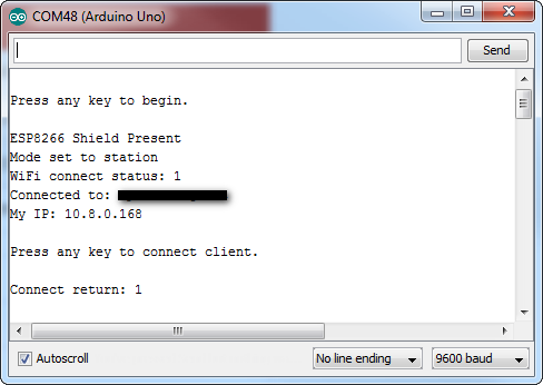
This example runs through some of the foundational functions of the ESP8266 AT library. It connects to an AP, finds it's local IP address, tries to connect to a remote server (example.com) to get a webpage, and finally sets up a server of it's own.
Opening up the serial monitor (set to 9600 baud), and following along with the instructions (you'll need to send a few characters to trigger events), will keep you informed on how the Shield is working.
Once you get to the final, server example of the sketch, try loading up a web browser and navigating to the displayed web address. The ESP8266 should serve up a web page like this:
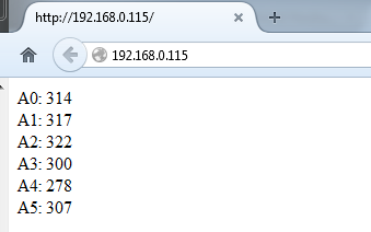
You will need to be on the same network for this to work.
Using the ESP8266 AT Library
The example from the previous section -- and the others included with the library -- should go a long way towards demonstrating the usage of the SparkFun ESP8266 AT library. This section will document some of the more commonly-used functions. For more documentation check out the library's GitHub repository.
Initialization
You'll need to include two libraries at the top of any ESP8266-using Arduino sketch: <SparkFunESP8266WiFi.h> and <SoftwareSerial.h>:
language:c
#include <SoftwareSerial.h> // Include software serial library, ESP8266 library dependency
#include <SparkFunESP8266WiFi.h> // Include the ESP8266 AT library
In your setup(), to initialize the ESP8266 and make sure it's functioning, call esp8266.begin(). This function will return either true or false, indicating if communication was successful with the ESP8266.
language:c
if (esp8266.begin()) // Initialize the ESP8266 and check it's return status
    Serial.println("ESP8266 ready to go!"); // Communication and setup successful
else
    Serial.println("Unable to communicate with the ESP8266 :(");
esp8266.begin() must be called before any other ESP8266 function.
Setting Up WiFi
To connect your ESP8266 to the local WiFi network, call esp8266.connect(). This function has two parameters: a network SSID and password. For example:
language:c
int retVal;
retVal = esp8266.connect("myNetwork", "myNetworkPassword");
if (retVal < 0)
{
    Serial.print(F("Error connecting: "));
    Serial.println(retVal);
}
The connect() function will also return a value, indicating it's success. Any value greater than 0 indicates success. Any value less than 0 means there was some trouble connecting.
This function can take some time to complete -- the timeout in the library is set to 30 seconds.
After connecting, you can check your local IP address by calling esp8266.localIP(). This function will return a variable of type IPAddress.
language:c
IPAddress myIP = esp8266.localIP(); // Get the ESP8266's local IP
Serial.print(F("My IP is: ")); Serial.println(myIP);
TCP Client
Once you've connected to a network, you probably want to interact with the Internet! To use the ESP8266 as a TCP client, use the ESP8266Client class. First, create an object. You can have up to five simultaneous client's:
language:c
ESP8266Client client; // Create a client object
Once the client is created, you can call the connect() member function to connect to a destination server. This function requires two parameters: a destination server (IPAddress or String) and a destination port.
For example, to connect to sparkfun.com on port 80, after creating the client object call:
language:c
retVal = client.connect("sparkfun.com", 80); // Connect to sparkfun (HTTP port)
if (retVal > 0)
    Serial.println("Successfully connected!");
connect() will return a number greater than 0 on success, and a negative value if it fails.
Once you've connected to a server, you can use the standard stream functions to send and receive data. For example, to send an HTTP request use client.print()
language:c
client.print("GET / HTTP/1.1\nHost: example.com\nConnection: close\n\n");
Or to read what the server sends back, use client.available() and client.read():
language:c
while (client.available()) // While there's data available
    Serial.write(client.read()); // Read it and print to serial
Finally, to close a client connection, call client.stop().
The ESP8266 AT Library is capable of even more: you can set up a TCP server, turn the ESP8266 into an access point, for example. Load up one of the other examples in the library to give these other features a try.
(Re-)Programming the ESP8266
The ESP8266 works great and it's cheap, but it can be so much more than a simple AT-command-driven serial-to-WiFi gateway! It can be reprogrammed just like any microcontroller, and you can even load Arduino sketches onto it.
Danger zone! Uploading new code to the ESP8266 will overwrite the AT command firmware it ships with. You can always put that firmware back on, but the AT library probably won't work with whatever custom code you load onto the ESP8266.
This section is included with this tutorial, in case anyone wants to use the ESP8266 WiFi Shield as more of a general purpose ESP8266 development board. You can skip it if you intend on using the Shield as an actual Arduino Shield.
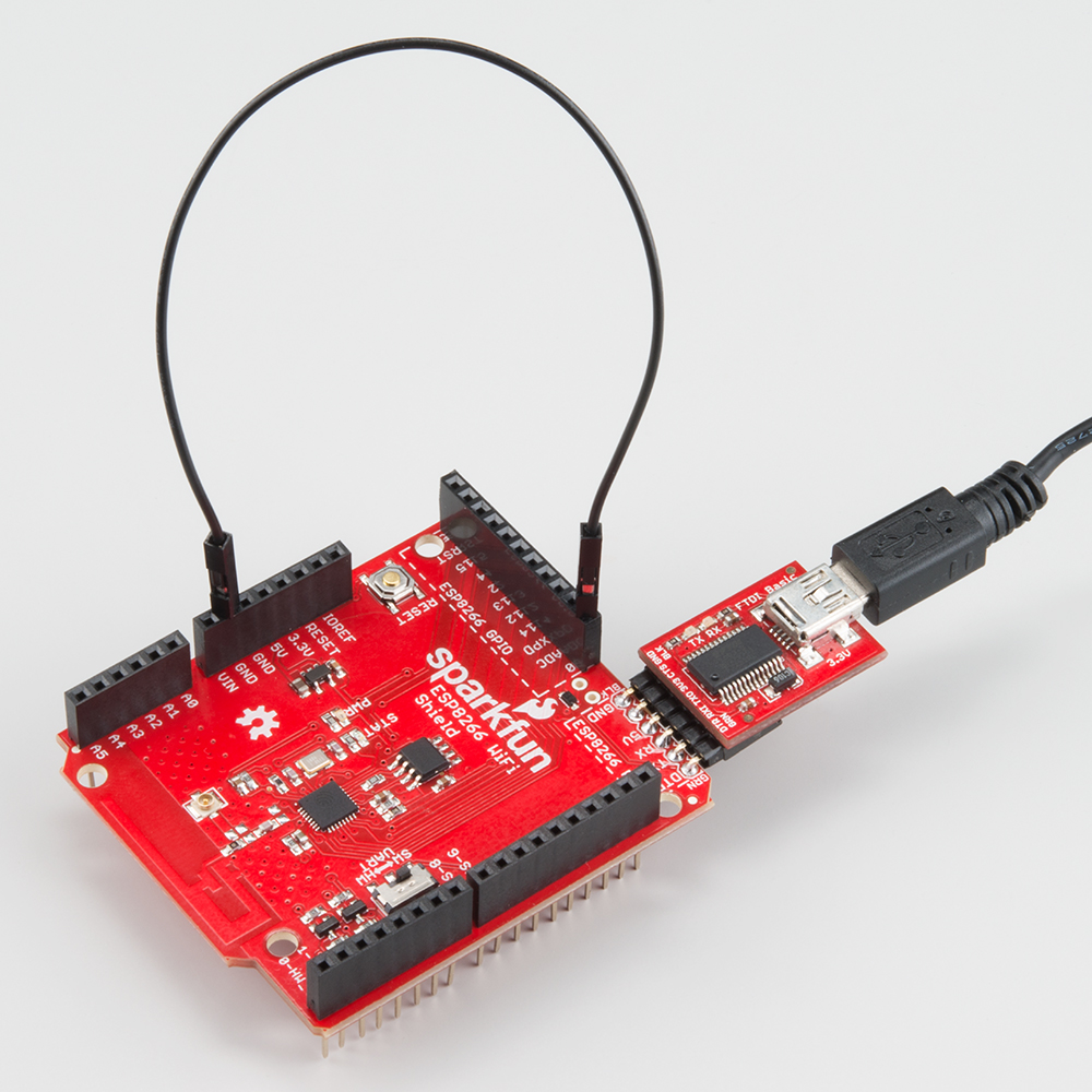
Programming Hardware
To load code onto the ESP8266 WiFi Shield, you'll need a couple extra bits of hardware: a 5V FTDI Basic and a wire.
Actually, any device that can translate computer-speak (either USB or RS-232) to TTL serial could work (see the old RS232 Shifter), but the FTDI Basic and it's FTDI Cable counterpart work best, as they mate directly with the ESP8266 WiFi Shield's programming header.
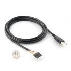
You'll also need a jumper wire to easily connect and disconnect GPIO0 from GND. GPIO0 controls the ESP8266's run mode -- if it's LOW (0V, GND) when the chip boots up, it starts up its bootloader. If GPIO0 is high on bootup, it'll begin running its application code.
| GPIO0 Value | ESP8266 Mode |
|---|---|
| HIGH (3.3V) | Run Program |
| LOW (0V) | Bootloader |
There is a pull-up resistor attached to GPIO0, so all you should need to do is pull it to GND when uploading code and leave it floating otherwise. There are a variety of ways to achieve this connection, the easiest of which may be running a male-to-male jumper wire between female headers.
If you're going to be doing a lot of code uploads, perhaps you'll want to set up a switch between GND and floating.
Installing the Addon With the Arduino Boards Manager
With the release of Arduino 1.6.4, adding third party boards to the Arduino IDE is easily achieved through the new board manager. If you're running an older version of Arduino (1.6.3 or earlier), we recommend upgrading now. As always, you can download the latest version of Arduino from arduino.cc.
This ESP8266 addon for Arduino is based on the amazing work by Ivan Grokhotkov and the rest of the ESP8266 community. Check out the ESP8266 Arduino GitHub repository for more information.
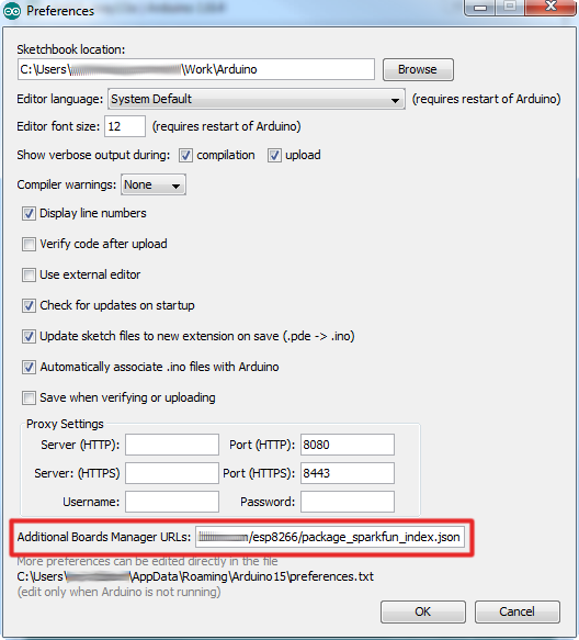
To begin, we'll need to update the board manager with a custom URL. Open up Arduino, then go to the Preferences (File > Preferences). Then, towards the bottom of the window, copy this URL into the "Additional Board Manager URLs" text box:
https://raw.githubusercontent.com/sparkfun/Arduino_Boards/master/IDE_Board_Manager/package_sparkfun_index.json
If you already have a URL in there, and want to keep it, you can separate multiple URLs by placing a comma between them.
Hit OK. Then navigate to the Board Manager by going to Tools > Boards > Boards Manager. There should be a couple new entries in addition to the standard Arduino boards. Look for SparkFun ESP8266 Development Boards. Click on that entry, then select Install.
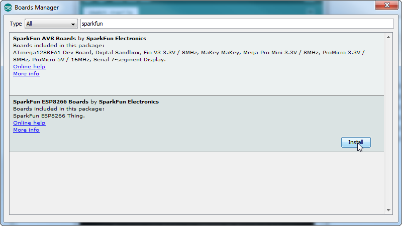
The board definitions and tools for the ESP8266 Thing include a whole new set of gcc, g++, and other reasonably large, compiled binaries, so it may take a few minutes to download and install (the archived file is ~110MB). Once the installation has completed, an Arduino-blue "INSTALLED" will appear next to the entry.
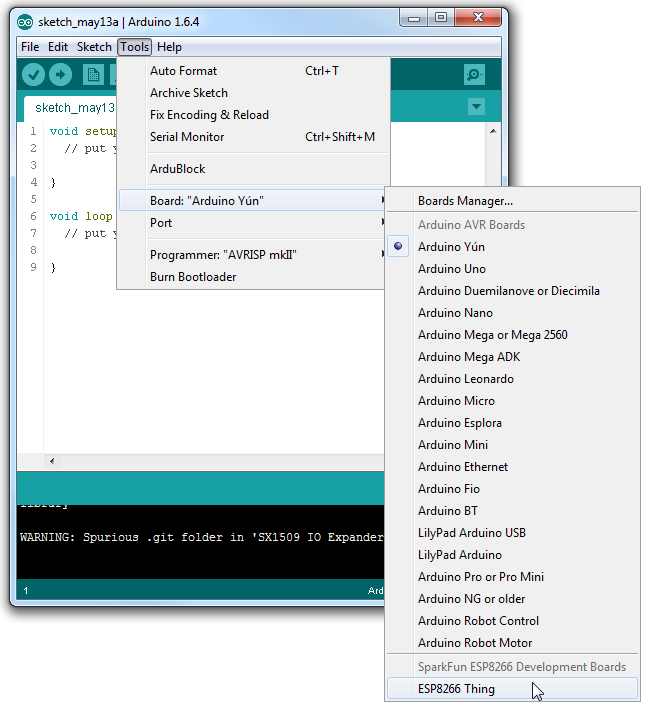
Selecting the ESP8266 Board
With the Board addon installed, all that's left to do is select the proper board from the Tools > Boards menu. Under that menu, find "SparkFun ESP8266 Thing" and select that.
Then select your FTDI's port number under the Tools > Port menu.
Uploading and Running a Sketch
Now that you've got the environment set up, it's time to upload some code. If you're using an FTDI Basic to upload code, you can also use that board to power the WiFi Shield. Remove the Shield from your Arduino, plug in the FTDI cable, and the power LED should illuminate.
Load up a simple blink sketch -- setting the blink pin to 5 (attached to the Shield's STAT LED).
language:c
#define ESP8266_LED 5

void setup()
{
  pinMode(ESP8266_LED, OUTPUT);
}

void loop()
{
  digitalWrite(ESP8266_LED, HIGH);
  delay(500);
  digitalWrite(ESP8266_LED, LOW);
  delay(500);
}
Don't forget, when you upload a sketch to the ESP8266, to make sure GPIO0 is connected to GND. Viola! You're on your way to being an ESP8266 developer! For more guidance on ESP8266 development, check out our ESP8266 Thing Hookup Guide, notably the sections starting around the example sketches.
Resources and Going Further
The ESP8266 WiFi Shield is open source hardware, you can find all of our design documents in our ESP8266 WiFi Shield GitHub Repository. In addition to that, these resources may come in handy:
ESP8266 Resources
An awesome community has grown around the ESP8266. We owe them big time for the amazing Arduino addon they've cooperatively built. For all of your ESP8266 needs, we recommend checking out the esp8266.com Community Forum. In addition to that, here are a few ESP8266-related resources we've found incredibly helpful:
- ESP8266 GitHub User Repos -- Tons of incredible tools can be found here. From Crosstool (to compile your own Xtensa GCC, G++, etc.) to the ESP8266 Arduino GitHub Repo
- ESP8266 Community Wiki -- Related to the community forum, there's a good amount of information available in this wiki.
- NodeMCU Firmware and the NodeMCU Flasher -- NodeMCU is a popular firmware for the ESP8266. It implements a LUA-based interpreter on the ESP8266 MCU.
- Espressif Board Forums -- Espressif, the manufacturers of the ESP8266, have a forum of their own. You can sometimes find updated software development kit downloads, or other helpful links here.
- Espressif GitHub Repos -- Espressif is also somewhat active on GitHub. They host a couple versions of the SDK here.
The ESP8266 Thing is open source hardware! If you need, or just want to look at, the PCB design files, you can find them in our ESP8266 Thing GitHub repository.
Going Further
Need a little project inspiration, now that you've got your ESP8266 Thing up-and-running? Maybe some of these related SparkFun tutorials will help spur some ideas:
Are You Okay? Widget
With it's deep sleep ability, the Thing is a great foundation for a WiFi-based weather station, or a friendly, huggable, interactive plushy.