Wireless Motor Driver Shield Hookup Guide
 Nick Poole,
  Shawn Hymel
 Introduction
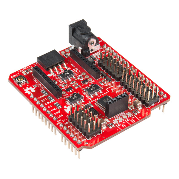
The Wireless Motor Driver Shield is an Arduino shield designed to make it easier and faster to connect motors and sensors to your Arduino compatible development board. It's really handy for throwing together remote control rovers and small autonomous robots. This guide will get you up and running with your very own Wireless Motor Driver Shield!
Required Materials
Aside from the Wireless Motor Driver Shield, you will also need to stack the shield to a microcontroller. We recommend the SparkFun RedBoard or any other Arduino form factor boards such as the Arduino Uno or the Arduino Leonardo.
One of the main features of the Driver Shield is to make working with motors easier for those just learning. In order to fully utilize this shield, you'll also need some motors to drive. Check out our Motors Category for some ideas.
Suggested Reading
You may find some of the following concepts useful before using your Driver Shield.
Serial Communication
What is an Arduino?
Installing Arduino IDE
Serial Terminal Basics
Motors and Selecting the Right One
Arduino Shields v2
Hardware Overview
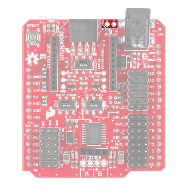
The Wireless Motor Driver Shield has a number of connectors, switches, and ports for you to use. Let's take a look at each one.
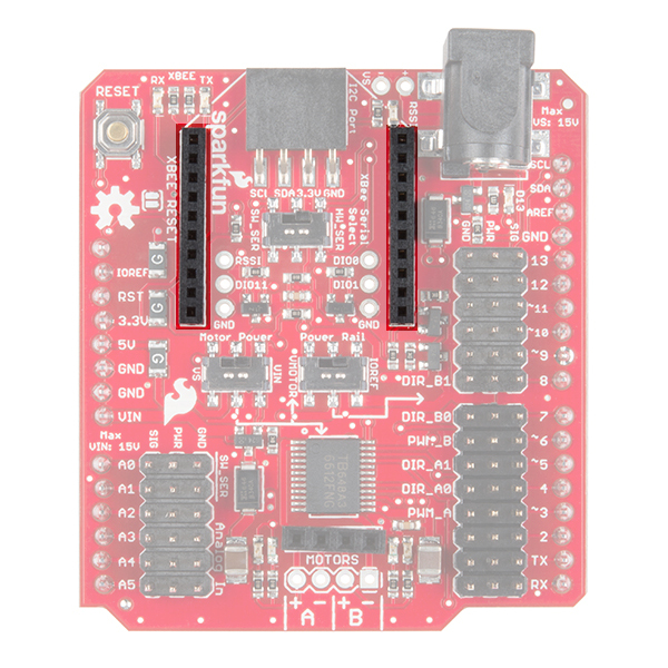
XBee Port
At the top of the board, you will find two rows of headers meant to accept an XBee module. The XBee UART is connected to digital pins 0 and 1 or analog pins A0 and A1, depending on the position of the XBee selector switch.
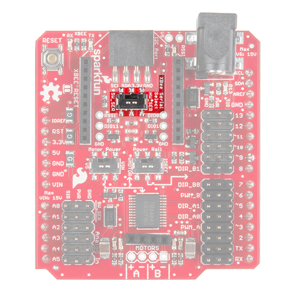
XBee Pins Select Switch
The selector switch underneath the XBee port allows you to choose which pins to use to communicate to the XBee module. The table below shows which pins on the Arduino the XBee RXI and TXO pins are connected to, depending on the switch's position. If you use SW_SER (pins A0 and A1), you'll need to use the Software Serial library.
So, if you plan to use HW_SER to communicate to the XBee, you'll need to switch it to SW_SER when uploading new code. When code has finished uploading to the Arduino, the switch will need to be flipped back to the HW_SER side to communicate to the XBee.
| Position | XBee RXI | XBee TXO |
|---|---|---|
| HW_SER | 0 | 1 |
| SW_SER | A0 | A1 |
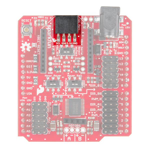
I2C Port
Under the XBee footprint, you'll also find a 4-pin female header that breaks out the Arduino's I2C lines. You can use this to attach various sensors to your project.
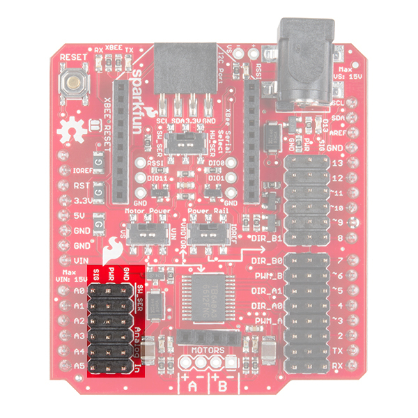
Analog Input Pins
On the left side of the shield, you'll find pins A0 through A5 broken out to headers with power and ground pins for each analog pin. Be aware that if you select SW_SER on the XBee switch, pins A0 and A1 will be used to connect to the XBee's RXI and TXO, respectively.
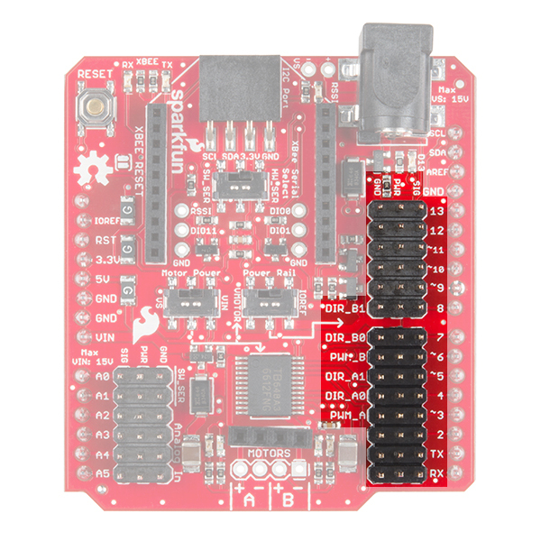
Digital Pins
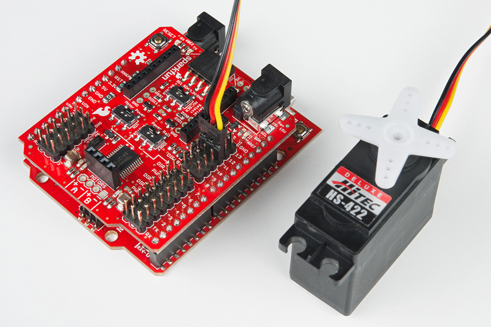
On the right side, you'll see digital pins 0 through 13 broken out to headers with a power and ground pin for each pin. These are configured this way to allow you to easily connect servos. Note that the power pins can be connected to IOREF, VIN, or the Shield's power jack, depending on the position of the 2 power switches.
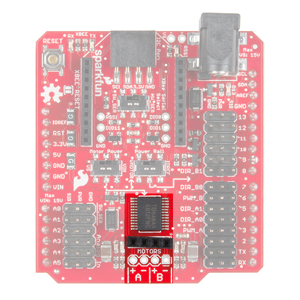
Motor Driver and Output
At the bottom of the Shield, you'll find a TB6612FNG motor driver and a 4-pin header for connecting any number of DC motors. The unpopulated holes are spaced 0.100 inch apart and available for soldering wires from your motor(s).
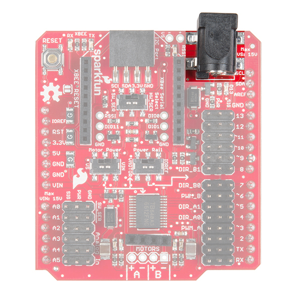
Power Jack
Often, driving motors from the Arduino's power supply (even VIN) will cause the voltage to dip and possibly reset your Arduino. To help with this issue, the power jack on the top-right of the Shield will accept a 5.5 x 2.1mm power plug from a variety of wall adapters and battery packs.
Note that you will need to set the Motor Power switch to VS to power the motors from the power jack. If you also set the Power Rail switch to VMOTOR, then the power jack will be connected to the PWR rail on the digital pins (e.g. to power servos).
Additionally, this power jack will not power the Arduino. It is intended to provide a power supply to your motors separate from your Arduino.
In addition to the power jack, the VS pins are broken out next to the barrel jack connector as "+" and "-".
 |
 |
| Add Electrical Tape where the Arduino Uno's USB Connector is Exposed on the Top | Add Electrical Tape where the External VS Power Pins are Exposed on the Bottom |
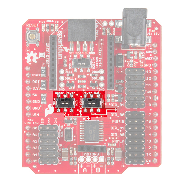
Power Switches
In the middle of the board are 2 switches that can be used to set how power is distributed to the digital PWR rail and motor driver. The Motor Power switch allows you to select between VS (power jack) and VIN (from Arduino) to supply power to the motors (labeled VMOTOR). The Power Rail switch allows you to select between IOREF (from Arduino) and VMOTOR (output of the Motor Power switch) to power the PWR pins on the digital headers.
| Motor Power Switch Position | Power Rail Switch Position | Motor Driver is connected to... | Digital PWR pins are connected to... |
|---|---|---|---|
| VS (power jack) | VMOTOR | VS (power jack) | VS (power jack) |
| VS (power jack) | IOREF | VS (power jack) | IOREF |
| VIN | VMOTOR | VIN | VIN |
| VIN | IOREF | VIN | IOREF |
Simple Motor Control
In this section, we'll review how to connect a pair of motors to the Wireless Motor Driver Shield and get them spinning. Before we do that, however, let's talk a little bit about how we talk to the H-Bridge Driver. If we look at the datasheet for the TB6612FNG we find a table like this:
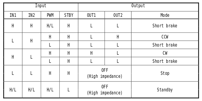
This table shows the relationship between the input and output pins on the H-Bridge. Each of the two channels requires 3 pins to operate: IN1, IN2 and PWM. By driving the IN pins high or low, you can control the direction of the motor on that channel as well as disengage it completely or even short it end-to-end (like pressing the brakes). The signal that you feed to the PWM pin determines the speed of the motor on that channel. By referencing the table above, we discover that in order to make the motor turn clockwise at 50% speed, we'll need set IN1 to High, IN2 to LOW and send a 50% PWM signal (that's analogWrite(pin, 128) in Arduino)
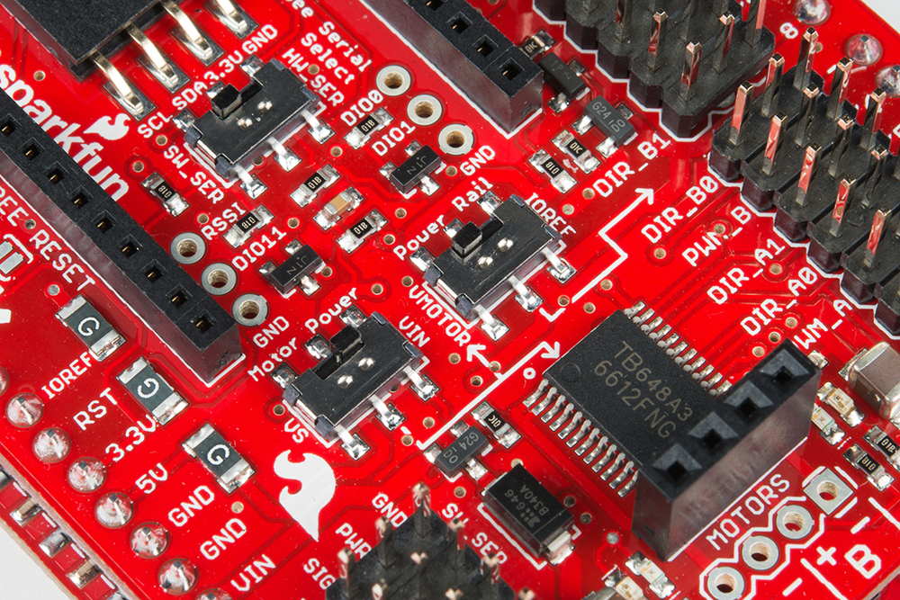
We can look at the silkscreen on the shield itself to find out which Arduino pins are connected to which inputs on the H-Bridge. Once we know that, we can start to write some basic example code to control the driver.
Before anything is going to move, we'll need to connect a pair of motors. If you're just starting out with robotics, we suggest the DAGU Hobby Gearmotors. These motors are the same ones that come with our Ardumoto Shield Kit. Since they have wires attached to the motors, plug them into the A+, A-, B+, and B- headers. The example code also allows you to control a servo, so if you'd like to add a servo, plug it into pin 11.
Now, attach the shield to a the SparkFun RedBoard (or any Arduino with the Arduino Uno footprint). Connect a power supply like a 9V battery holder and 9V battery. Once that's done, we can get the example code loaded onto the Arduino.
Note: This example assumes you are using the latest version of the Arduino IDE on your desktop. If this is your first time using Arduino, please review our tutorial on installing the Arduino IDE.
Copy the example code below, and paste it in the Arduino IDE. (As an alternative, you can also download the example code from the GitHub Repository). Connect your RedBoard or Arduino over USB, and make sure you have the correct board type and COM port selected. Now press "upload" to send the example code to the board!
language:c
/*
 * SparkFun Ludus ProtoShield Example Code
 * SparkFun Electronics
 * Nick Poole 2015
 *
 * This is an Arduino shield that integrates an H-Bridge Driver and
 * breaks out all I/O ports to three-pin headers on a GND/PWR/SIG
 * standard. This enables quick prototyping and integration of
 * Arduino projects w/o the need of a breadboard.
 *
 * Ludus is the mascot of the SparkFun Education team.
 * It is a highly intelligent octopus.
 *
 * Please see the License.md file for license information.
*/

#include <Servo.h>

Servo swivel;

int pwm_a = 3;   // Channel A speed
int pwm_b = 6;   // Channel B speed
int dir_a0 = 4;  // Channel A direction 0
int dir_a1 = 5;  // Channel A direction 1
int dir_b0 = 7;  // Channel B direction 0
int dir_b1 = 8;  // Channel B direction 1

char inbit; // A place to store serial input

int swivelpos = 90; // Servo position

void setup()
{

  Serial.begin(9600); // Pour a bowl of serial

  swivel.attach(11); // Attach servo to pin 11
  swivel.write(swivelpos);

  pinMode(pwm_a, OUTPUT);  // Set control pins to be outputs
  pinMode(pwm_b, OUTPUT);
  pinMode(dir_a0, OUTPUT);
  pinMode(dir_a1, OUTPUT);
  pinMode(dir_b0, OUTPUT);
  pinMode(dir_b1, OUTPUT);

  draw(); // Draw the driving instructions to the serial terminal

}

void loop()
{

if(Serial.available()){ // Wait for serial input

  inbit = Serial.read();

  switch(inbit){ // Switch based on serial in

    case 'w': // Move Forward

      forward(200);
      delay(30);
      shutoff();
      break;

    case 's': // Move Backward

      reverse(200);
      delay(30);
      shutoff();
      break;

    case 'q': // Turn Left while moving forward

      turnL(200);
      delay(30);
      shutoff();
      break;

    case 'e': // Turn Right while moving forward

      turnR(200);
      delay(30);
      shutoff();
      break;

    case 'a': // Spin Left in place

      spinL(200);
      delay(30);
      shutoff();
      break;

    case 'd': // Spin Right in place

      spinR(200);
      delay(30);
      shutoff();
      break;

    case 'x': // Short brake

      brake();
      break;

    case 'z': // Spin servo (on pin 11) left

      servoL();
      break;

    case 'c': // Spin servo (on pin 11) right

      servoR();
      break;

    }
  }
}

void forward(int speed) // Move Forward
{

digitalWrite(dir_a0, 0);
digitalWrite(dir_a1, 1);
digitalWrite(dir_b0, 0);
digitalWrite(dir_b1, 1);

analogWrite(pwm_a, speed);
analogWrite(pwm_b, speed);

}

void reverse(int speed) // Move Backward
{

digitalWrite(dir_a0, 1);
digitalWrite(dir_a1, 0);
digitalWrite(dir_b0, 1);
digitalWrite(dir_b1, 0);

analogWrite(pwm_a, speed);
analogWrite(pwm_b, speed);

}

void turnL(int speed) // Turn Left while moving forward
{

digitalWrite(dir_a0, 0);
digitalWrite(dir_a1, 1);
digitalWrite(dir_b0, 0);
digitalWrite(dir_b1, 1);

analogWrite(pwm_a, speed);
analogWrite(pwm_b, speed/4);

}

void turnR(int speed) // Turn Right while moving forward
{

digitalWrite(dir_a0, 0);
digitalWrite(dir_a1, 1);
digitalWrite(dir_b0, 0);
digitalWrite(dir_b1, 1);

analogWrite(pwm_a, speed/4);
analogWrite(pwm_b, speed);

}


void spinL(int speed) // Spin Left in place
{

digitalWrite(dir_a0, 0);
digitalWrite(dir_a1, 1);
digitalWrite(dir_b0, 1);
digitalWrite(dir_b1, 0);

analogWrite(pwm_a, speed/2);
analogWrite(pwm_b, speed/2);

}

void spinR(int speed) // Spin Right in place
{

digitalWrite(dir_a0, 1);
digitalWrite(dir_a1, 0);
digitalWrite(dir_b0, 0);
digitalWrite(dir_b1, 1);

analogWrite(pwm_a, speed/2);
analogWrite(pwm_b, speed/2);

}

void brake() // Short brake
{

digitalWrite(dir_a0, 1);
digitalWrite(dir_a1, 1);
digitalWrite(dir_b0, 1);
digitalWrite(dir_b1, 1);

analogWrite(pwm_a, 0);
analogWrite(pwm_b, 0);

}

void shutoff() // Stop Motors w/o braking
{

digitalWrite(dir_a0, 0);
digitalWrite(dir_a1, 0);
digitalWrite(dir_b0, 0);
digitalWrite(dir_b1, 0);

analogWrite(pwm_a, 0);
analogWrite(pwm_b, 0);

}

void draw() // Serial Instructions
{
  Serial.println("          DuckBot 2015          ");
  Serial.println("                                ");
  Serial.println("   -------------------------    ");
  Serial.println("   |       |       |       |    ");
  Serial.println("   |   Q   |   W   |   E   |    ");
  Serial.println("   | turnL |forward| turnR |    ");
  Serial.println("   -------------------------    ");
  Serial.println("   |       |       |       |    ");
  Serial.println("   |   A   |   S   |   D   |    ");
  Serial.println("   | spinL |reverse| spinR |    ");
  Serial.println("   -------------------------    ");
  Serial.println("   |       |       |       |    ");
  Serial.println("   |   Z   |   X   |   C   |    ");
  Serial.println("   |servo L| brake |servo R|    ");
  Serial.println("   -------------------------    ");
  Serial.println("                                ");
}

void servoL() // Spin servo (on pin 11) left
{

  if(swivelpos>10){
    swivelpos = swivelpos-10;
    swivel.write(swivelpos);
  }

}

void servoR() // Spin servo (on pin 11) right
{

  if(swivelpos<170){
    swivelpos = swivelpos+10;
    swivel.write(swivelpos);
  }

}
Make sure the Motor Power and Power Rail switches are set to VIN and VMOTOR, respectively.
If everything went well, you should now be able to open a serial terminal (such as the one built into the Arduino IDE), and type a bunch of "w"s to make the motors turn. This example was really written to be used with terminal programs, which allow you to type directly to the port without having to press return. That way, you can drive the robot by holding down the appropriate keys on your keyboard. My favorite terminal program for this is RealTerm. You can get RealTerm here.
You can also attach a servo to pin 11 and send the characters 'z' and 'c' through the Serial terminal to move the servo.
Now that we've seen this thing in action, let's dig through the example code. Understanding how the example code works is the first step towards writing your own!
Understanding the Example Code
The example code is designed to let you control the H-Bridge, as well as a servo attached to pin 11, using serial communication. Let's walk through a few excerpts from the code and see if we can understand a little better what's making it work. As with most sketches, it starts with some basic setup:
language:c
#include <Servo.h>

Servo swivel;

int pwm_a = 3; // Channel A speed
int pwm_b = 6; // Channel B speed
int dir_a0 = 4; // Channel A direction 0
int dir_a1 = 5; // Channel A direction 1
int dir_b0 = 7; // Channel B direction 0
int dir_b1 = 8; // Channel B direction 1

char inbit; // A place to store serial input
int swivelpos = 90; // Servo position

void setup()
{
Serial.begin(9600); // Pour a bowl of serial

swivel.attach(11); // Attach servo to pin 11
swivel.write(swivelpos);

pinMode(pwm_a, OUTPUT); // Set control pins to be outputs
pinMode(pwm_b, OUTPUT);
pinMode(dir_a0, OUTPUT);
pinMode(dir_a1, OUTPUT);
pinMode(dir_b0, OUTPUT);
pinMode(dir_b1, OUTPUT);

draw(); // Draw the driving instructions to the serial terminal

}
As you can see, we started out by including the servo library and creating a servo object called "swivel". Next, we declare a handful of variables to keep track of which pins are responsible for which functions, and also variables for the servo position and incoming serial characters. The setup() function is where serial communication is initialized, the servo object is attached and the control pins are all set as output devices. Finally, we call the function draw(), which we'll look at in a minute.
language:c
void loop()
{
if(Serial.available()){ // Wait for serial input
    inbit = Serial.read();
    switch(inbit){ // Switch based on serial in
        case 'w': // Move Forward
    forward(200);
    delay(30);
    shutoff();
    break;
        case 's': // Move Backward
    reverse(200);
    delay(30);
    shutoff();
    break;
        case 'q': // Turn Left while moving forward
    turnL(200);
    delay(30);
    shutoff();
    break;
        case 'e': // Turn Right while moving forward
    turnR(200);
    delay(30);
    shutoff();
    break;
        case 'a': // Spin Left in place
    spinL(200);
    delay(30);
    shutoff();
    break;
        case 'd': // Spin Right in place
    spinR(200);
    delay(30);
    shutoff();
    break;
        case 'x': // Short brake
    brake();
    break;
        case 'z': // Spin servo (on pin 11) left
    servoL();
    break;
        case 'c': // Spin servo (on pin 11) right
    servoR();
    break;
    }
}
}
The main loop of the example code just waits to see input on the serial line and then stores the incoming value and compares it against a list of cases. By scrolling through the switch/case statements, you can see the behavior associated with each serial character. The rest of the code is composed of the various procedures that are called in the main loop. Let's look at a few of these:
language:c
void draw() // Serial Instructions
{
Serial.println("                           ");
Serial.println(" ------------------------- ");
Serial.println(" |       |       |       | ");
Serial.println(" |   Q   |   W   |   E   | ");
Serial.println(" | turnL |forward| turnR | ");
Serial.println(" ------------------------- ");
Serial.println(" |       |       |       | ");
Serial.println(" |   A   |   S   |   D   | ");
Serial.println(" | spinL |reverse| spinR | ");
Serial.println(" ------------------------- ");
Serial.println(" |       |       |       | ");
Serial.println(" |   Z   |   X   |   C   | ");
Serial.println(" |servo L| brake |servo R| ");
Serial.println(" ------------------------- ");
Serial.println("                           ");
}
This one is pretty straightforward! The draw() procedure is just a bunch of print statements that tell you which keys are attached to which functions.
Finally, there are a bunch of procedures that actually set the speed and direction of the motors. These are the functions that you'll want to borrow for your own code because they wrap up all of the control pin stuff we talked about in the last section into intuitive commands like "forward," "turn," and "brake." All of the motion commands are basically structured the same. For example:
language:c
void forward(int speed) // Move Forward
{
digitalWrite(dir_a0, 0);
digitalWrite(dir_a1, 1);
digitalWrite(dir_b0, 0);
digitalWrite(dir_b1, 1);

analogWrite(pwm_a, speed);
analogWrite(pwm_b, speed);
}
The brake() and shutoff() functions are structured the same as the motion procedures except that in the case of brake(), all of the pins are written high, and in the case of shutoff(), all of the pins are written low. The brake() procedure actually shorts the motor so that it resists turning. The shutoff() function simply shuts off power to the motors so that they come to a rolling stop. Try referring to the example code that was copied from Simple Motor Control for more details on how these functions were defined.
Finally, there are the servo control functions, which increment or decrement the servo position variable before writing it to the servo:
language:c
void servoL() // Spin servo (on pin 11) left
{
if(swivelpos>10){
swivelpos = swivelpos-10;
swivel.write(swivelpos);
}
}
The only kind of clever thing going on here is that we check ahead of time whether we've reached the limits of the servo so we can't increment beyond its range of motion.
Going Wireless
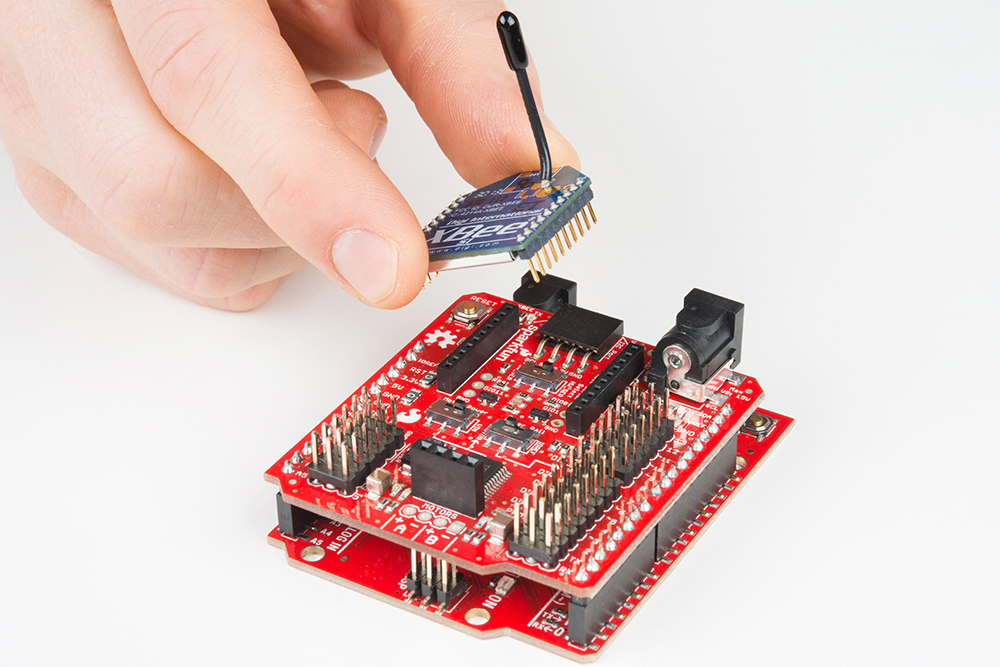
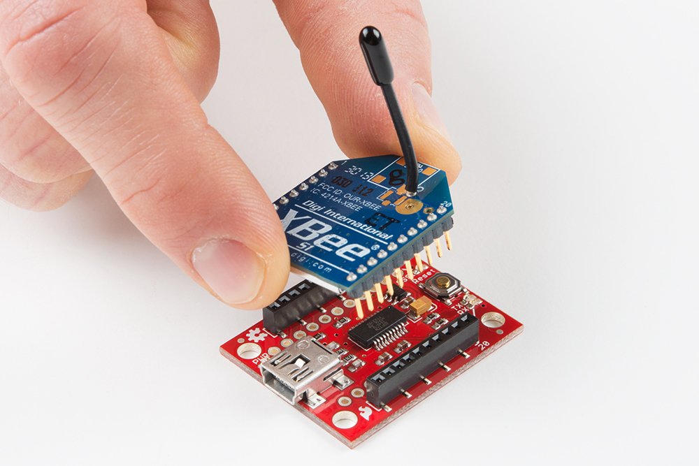
By using the power of ZigBee, you can free your project from its USB tether! Do do this, you'll need a pair of XBee radio modules and an XBee Explorer USB. Even if you're not familiar with XBee, you should be able to run the example code wirelessly as the radio modules should be configured properly by default. For an introduction to XBee, check out this SparkFun tutorial for getting started with XBees. There's a lot more you can do with XBee than what we'll cover here.
The first step is to plug an XBee radio into the Wireless Motor Driver Shield. The silkscreen on the board shows which orientation it should go. Make sure that the slide switch marked XBee Serial Select is set to HW_SER.
This will connect the XBee radio to the hardware serial lines of the Arduino. Next, plug your XBee Explorer into the USB port on your computer and open the serial terminal program that you were using in the Simple Motor Control section.
Open the COM port for the XBee Explorer, and switch the Arduino on.
The example code should now work exactly as it did before, only this time, your serial commands are being sent over the air! What's happening is that the XBee radio is acting like a wireless serial tunnel. As far as the Arduino knows, there's a USB cable hooked up to the serial line.
Resources and Going Further
Hopefully by now, you've built yourself a robot to play with! Getting moving is just the start, though. For more information, check out the resources below:
- TB6612FNG Motor Driver Datasheet
- Wireless Motor Driver Shield GitHub Repository
- Example code
- Arduino Software Serial Library
Check out some of our other robotics tutorials to take your Wireless Motor Driver Shield to the next level.