MIDI Shield Hookup Guide
 Byron J.
Introduction
The Sparkfun MIDI Shield allows you to add MIDI ports to your R3-compatible Arduino board.
The shield provides the standard MIDI port circuits, including 5-pin DIN connectors and an opto-isolated MIDI input. The shield also has some extra input and output devices. It had LEDs on D6 and D7, pushbuttons on D2, D3 and D4, and rotary potentiometers on A0 and A1.
The V1.5 revision also adds several configurable features, such as converting the MIDI output to a MIDI thru, and the option to use a software serial port for MIDI, leaving the hardware serial for programming and debugging. It also buffers the output, making it compatible with the Arduino Pro without needing to circumvent the protection resistors on the serial TX and RX lines.
This guide will show you how to put the shield together, then explore several example projects, demonstrating how you can apply MIDI to your projects.
Suggested Reading
- If you're new to MIDI, our MIDI Tutorial should help you get up to speed.
- We're going to use the 47 Effects MIDI Library as the heart of the example projects.
Assembly
Before assembling your MIDI shield, consider how you're going to use it. If you don't need buttons and potentiometers, you can leave them off. Similarly, if you only need the MIDI input or output port, you can leave the other port off. Finally, there are a couple of options for headers -- you can select headers that fit your application.
Materials
The MIDI shield kit contains the following parts.
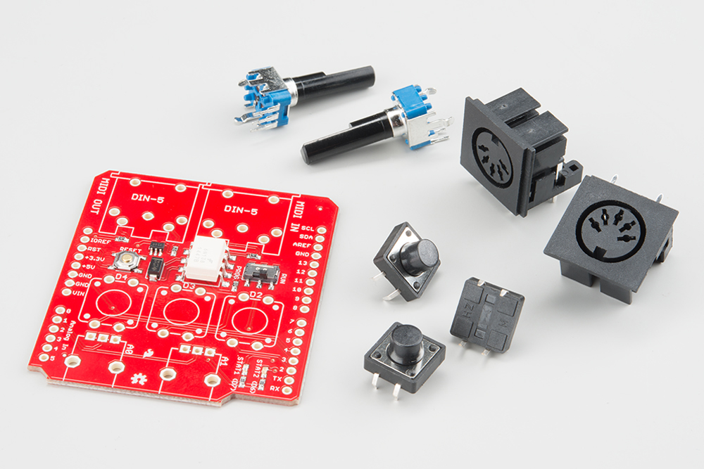
- The MIDI Shield PCB
- 2x 5-pin DIN conectors
- 2x 10K rotary potentiometer
- 3x 12mm tactile pushbutton switches
You'll also need to select headers that fit your application.
- You can use the R3 stackable header kit, but they're a bit tall and make the buttons hard to reach.
- If you're using an Arduino board that predates R3, such as the Arduino Pro, you can use the regular stackable header kit.
- Alternately, you can use regular snappable headers, which don't stick as far above the board, leaving plenty of room to access the switches and potentiometers.

Tools
The following tools are recommended.
- A soldering iron with a fine-point tip.
- Some solder, either leaded or lead-free.
- A magnifying glass or loupe.
- A vise to hold the PCB as you work.
Building The MIDI Shield
If you're using stackable headers, they're easiest to put on at the very beginning (if you're using the snappable headers, we'll save them until the end). To install the stackable headers, put them through the board from the top side
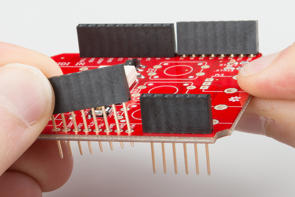
Then flip the board over so it's supported by the bodies of the headers. Adjust the alignment until the headers stand squarely in your work surface, and solder them in place.
Next, we'll install the components on the top of the board in order from the shortest to the tallest. We'll start with the pushbuttons -- snap them through the holes, then solder them in place.

Following that, install the MIDI jacks, taking care to keep them seated to the PCB while you solder.
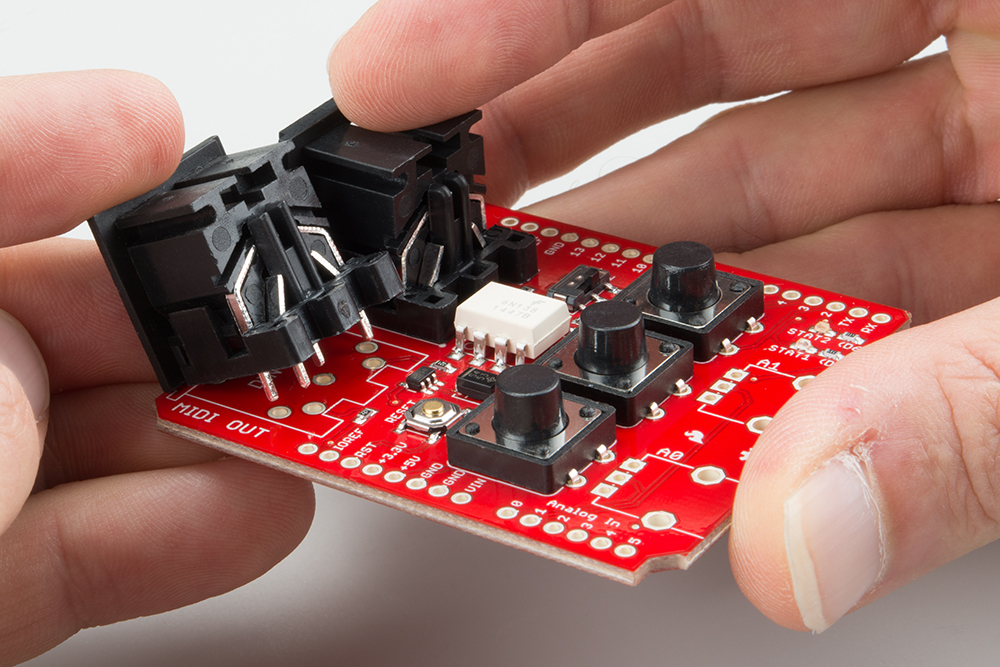
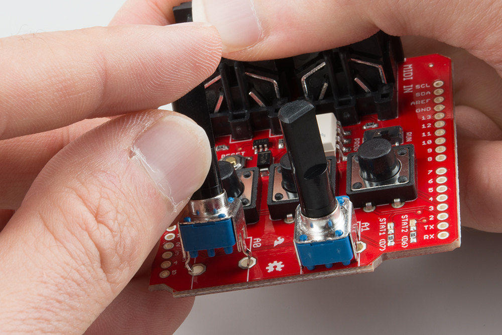
As the tallest component, the potentiometers go on next. Getting them into the PCB can take some effort -- you might need to nudge the tabs a little bit to get them through the board. Before you solder, doublecheck that the shafts are perpendicular to the surface of the board, because it takes a lot of desoldering effort to straighten them if they're crooked.
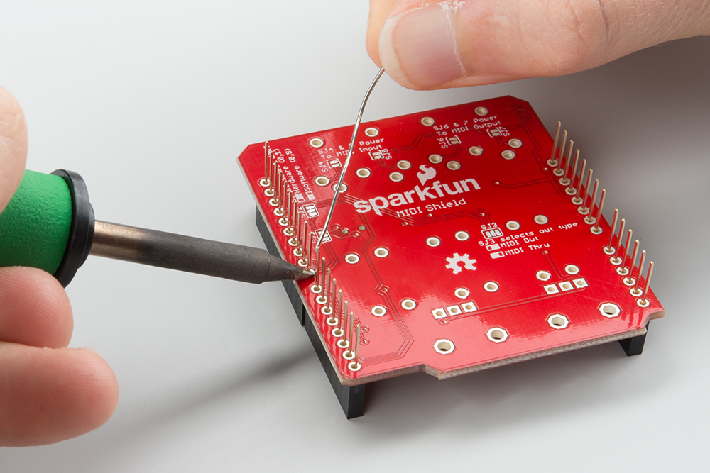
Finally, if you're using snappable headers instead of the stacking ones, install them. It's easiest if you use an Arduino board as an assembly jig. Snap the headers into suitable lengths (6, 8, 8 and 10 for an R3 board), and push them into the sockets on the Arduino. Then lay the MIDI shield PCB over them, as shown below.
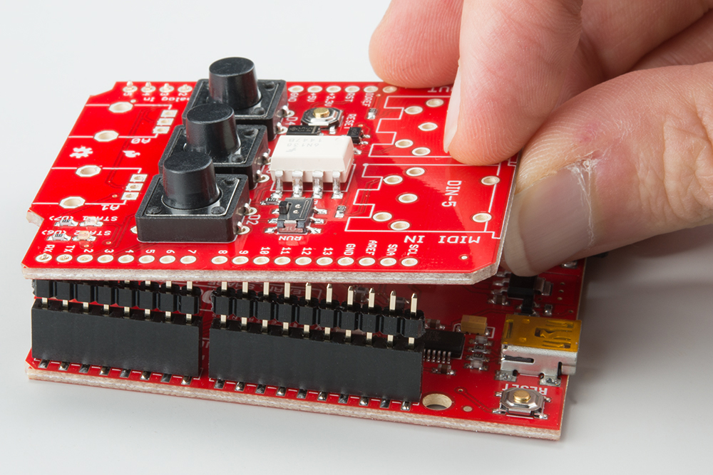
Solder them from the top of the board.
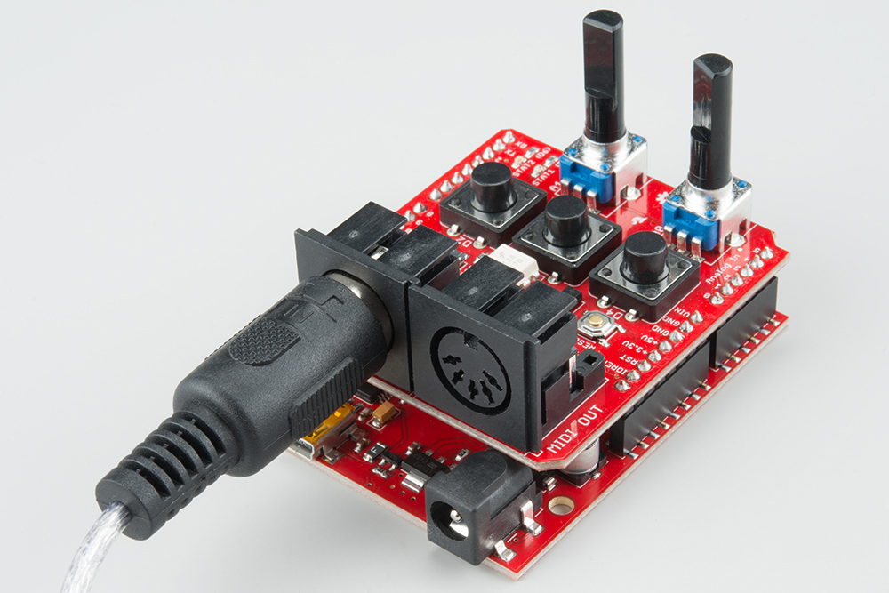
In Operation
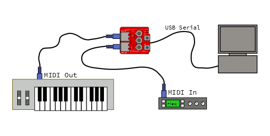
One it's assembled, place the MIDI shield on top of your Arduino, then connect your MIDI devices to the ports.
RUN vs. PROG
There's one last thing to mention: near the MIDI input jack is a small slide switch.
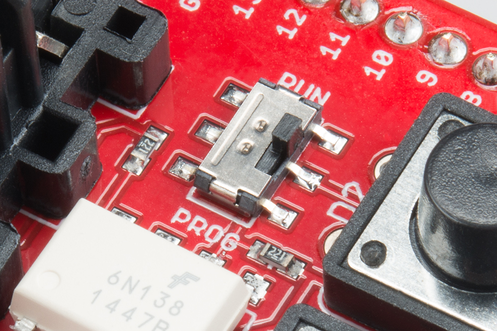
By default, the shield uses the hardware serial port on the Arduino for MIDI communication -- but that port is shared with the bootloader, which is initiated when you press the "load" button in the Arduino IDE. The switch allows them to share the port politely, avoiding output contention.
If you're using the hardware serial port, set the switch to the PROG position, before you load your sketch. Once it's loaded and verified, set it back to RUN.
In the next section we'll discuss using a software serial port. One advantage of software serial is that you don't need to remember to flip the switch every time you load!
Configuration
The MIDI Shield has a number of solder jumpers on the bottom side, so that it can be customized for different situations.
Hardware vs. Software Serial Port
The first set of jumpers are SJ1 and SJ2, near digital pins 10-13. These allow you to swap between the hardware serial port on pins D0 and D1, or a software serial port on pins 8 and 9.
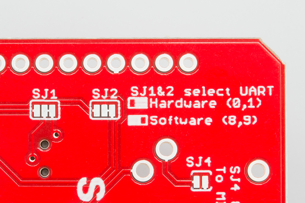
By default, these are connected with a copper trace between the center and right-hand pads, selecting the hardware UART. If you'd rather use the software serial port, cut that trace using a hobby knife, and flow some solder the bridge the center pad to the left one.
Why would you want to do this? A couple of reasons jump to mind.
- If you're using the software serial port for MIDI, the hardware port is still available to the bootloader. You don't need to toggle the RUN/PROG switch every time you try to load.
- The hardware serial port is still available for other communication. In particular, you can use
Serial.print()statements to debug your code.
MIDI Out or Thru
SJ3 is on the bottom of the board, near the center.
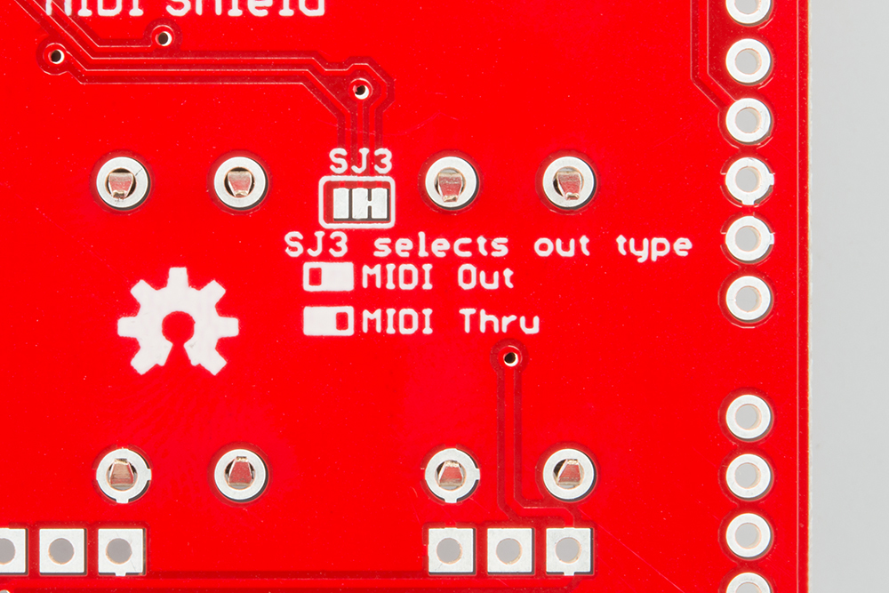
It allows the MIDI output port to be repurposed as a MIDI thru. Instead of being tied to the TX line of the selected serial port, the MIDI out jack will retransmit a copy of bytes that arrive at the input. If you don't need the MIDI output to transmit data, MIDI thru might be useful, especially if you're daisy chaining MIDI devices.
Like the serial port selection jumpers, the default path is connected with a copper trace. If you want to switch the jumper, cut the trace, and bridge the other two pads with solder.
The MIDI library we'll be using also has the option to enable software thru functionality.
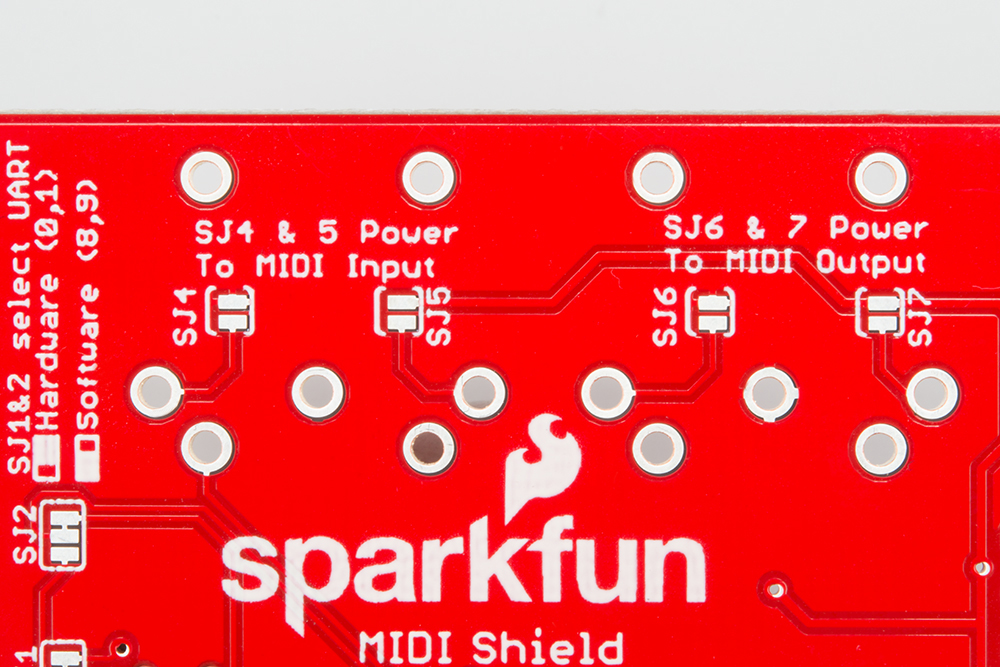
Power Over MIDI
The final set of jumpers is SJ4, 5, 6 and 7. These are under the MIDI ports and implement for a form of power-over-MIDI.
Power over MIDI isn't actually defined by the MIDI Standard, and a number of manufacturers have proposed and implemented different schemes for providing power to a device over the MIDI cable.
There isn't much agreement on how this is implemented. Some vendors add two extra pins, using a 7-pin connector. Some vendors simply sip a tiny bit of current off pin 4, and some use the pins that are otherwise not used in standard. Similarly, the voltage available differs -- it might be 5 VDC, 12 VDC, or sometimes even 12 VAC!
Since Arduinos don't have a 12 VDC supply, the MIDI shield allows you to route 5V to the unused pins of the 5-pin DIN connector: pin 1 is tied to 5V, and pin 3 gets grounded. This is mainly useful if you want to use a pair of MIDI shields to build a system with a subordinate device (like a MIDI enabled footpedal) that is powered by the larger system it's connected to.
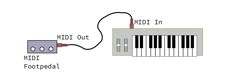
In a configuration like this, the shield on the pedal end would have the jumpers on the output closed (SJ6 and 7), and the shield on the host system end would have the input jumpers closed (SJ4 and 5).
This configuration allows you to power one MIDI Shield from another, but it may not be interoperable with other gear. Carefully consult the user manual of other devices before connecting them. Additionally, it requires a cable that has all five pins connected. The average MIDI cable has no connections to pins 1 and 3; sometimes MIDI cables are sold as having all five pins connected, and sometimes such a cable is simply sold as a "five pin DIN" cable.
There are some other technical concerns when powering devices over MIDI.
- It's most useful when the power provider and recipient are designed as a system. It's hard to make power over MIDI universally applicable, because you need to be able to anticipate voltage and current requirements.
- The original MIDI hardware implementation uses optocouplers to avoid ground loops. Power over MIDI invites ground loop-related problems by tying the grounds of different devices together.
Firmware Foundations
Arduino Compatible I/O
The MIDI shield features the MIDI circuitry, plus a few extra input and output devices. It has three pushbuttons, two potentiometers, and two LEDs.
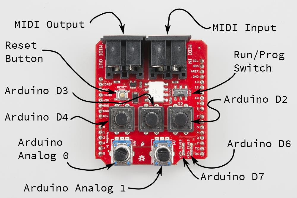
These devices are legended with their pin assignments, and can be interfaced using standard Arduino functions.
- The pushbuttons are on D2, D3, and D4. To use them, enable the corresponding pins as inputs with pullup
pinMode(<pin number>, INPUT_PULLUP);and read them withdigitalRead(<pin number>);. The inputs are active low - they will normally read as a logicHIGH, goingLOWwhile the button is pressed. - The potentiometers are connected to A0 and A1. You can read them using
analogRead(<pin number>). - Finally, the LEDs are on D6 (Green) and D7 (Red). The outputs are enabled using
pinMode(<pin number>, OUTPUT), and set usingdigitalWrite(<pin number>, <HIGH or LOW>). Like the buttons, these are active low -- writing HIGH turns the LED off.
You can find a quick example sketch to test the buttons, pots and LEDs in the MIDI Shield GitHub Repository.
Arduino Library Install
Note: This example assumes you are using the latest version of the Arduino IDE on your desktop. If this is your first time using Arduino, please review our tutorial on installing the Arduino IDE.
We'll be using the following libraries as the basis for the following examples. We'll discuss some specifics of its application in each example. If you have not previously installed an Arduino library, please check out our installation guide.
Installing an Arduino Library
Arduino MIDI Library
If you've read the implementation section of our MIDI tutorial, then you've seen that generating and parsing MIDI messages can be a little tricky. Thankfully, Franky at Forty Seven Effects has written a stable and flexible MIDI library for Arduino, which he has released under the MIT license.
The library handles the communication aspects of MIDI, allowing you to send and receive MIDI commands. It implements the communication layer, but it does not make any implications about how the library is applied. It is a suitable basis for almost any type of MIDI device, from simple message filters and splitters, to complex applications like synthesizers, sequencers, and drum machines.
The library is robust and flexible, with some well-designed features.
- It can use hard or soft serial ports -- you don't need to lose
Serial.print()for debugging when you use it. - It can handle MIDI in Omni mode or be set to a specific channel.
- You can enable a soft-thru feature, which merges incoming bytes with the output, when you don't have a hardware thru port available.
- It uses a object-oriented template instantion, which allows you to declare multiple MIDI ports on the same device, as you might do in a merger or splitter.
- You can enable or disable some more esoteric features, like sending running status and implicit note off, or using a nonstandard baud rate.
You can obtain this library through the Arduino Library Manager. Do a search for "midi" and scroll down the results to find the "MIDI Library by Forty Seven Effects." To manually install the library, download the files from GitHub repository. Unzip them, and put the contents of the ...\src folder into your Arduino library path. On the author's PC, the library was placed in C:\Users\author\Documents\Arduino\libraries\MIDI. You can also download the repo with the link below.
There is also extensive documentation in Doxygen format, including several sample applications.
MsTimer2 Library
The examples also use the MsTimer 2 library. You can obtain this library through the Arduino Library Manager. Do a search for "mstimer" to find "MsTimer2 by Javier Valencia." To manually install the library, download the files from GitHub repository. You can also download the repo with the link below.
Example #1: Clock Generator & Receiver
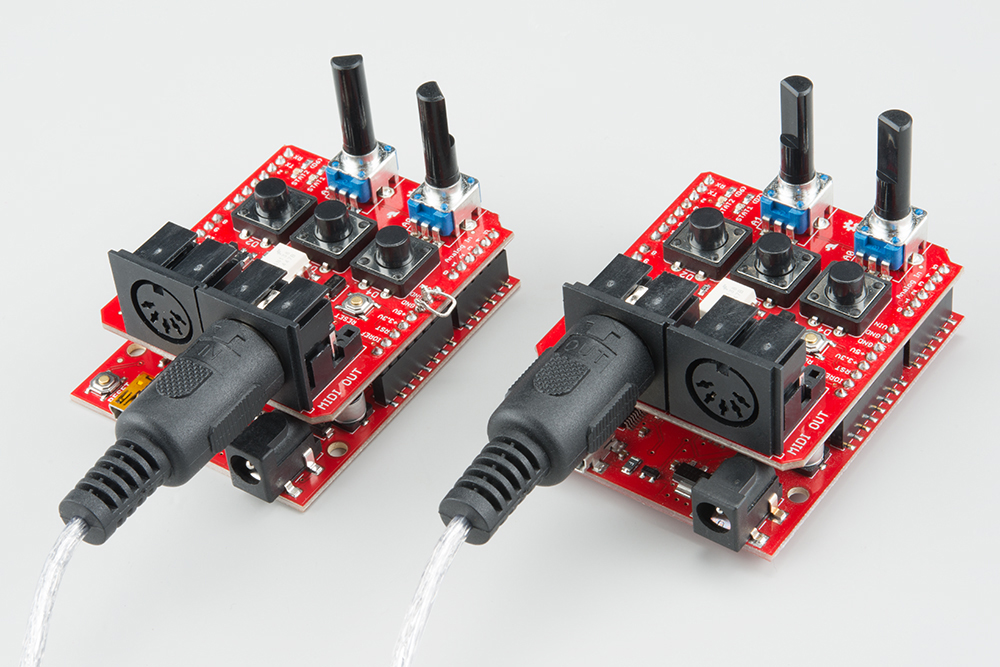
The first example we'll demonstrate is synchronizing multiple devices using MIDI clock commands.
For this example, we'll be building two different variants of the clock code. The first variant is the master clock, which generates periodic MIDI timing clock (0xF8) bytes, and start(0xFA), stop (0xFC), and continue (0xFB) messages. These messages are used to transmit musical timing from one device to another, acting as a high resolution metronome.

The other end of the link listens for those messages and responds to them.
For this demonstration, we'll be using a pair of RedBoards, each with a MIDI shield. You can substitute either end of the link for a device that implements MIDI clock, as we'll show below.
The Firmware
Each of these boards gets loaded with a different sketch. The master clock will get loaded with the clock-gen.ino sketch.
/******************************************************************************
clock-gen.ino
Use SparkFun MIDI Shield as a MIDI clock generator.

Byron Jacquot, SparkFun Electronics
October 8, 2015
https://github.com/sparkfun/MIDI_Shield/tree/V_1.5/Firmware/clock-gen

Generate MIDI clock messages at the tempo indicated by  A1.
Send start/stop messages when D2 is pressed, and continue when D3 is pressed.

Resources:

  This sketch has a clock receiving counterpart in clock-recv.ino

  This code is dependent on the FortySevenEffects MIDI library for Arduino.
  https://github.com/FortySevenEffects/arduino_midi_library
  This was done using version 4.2, hash fb693e724508cb8a473fa0bf1915101134206c34
  This library is now under the MIT license, as well.
  You'll need to install that library into the Arduino IDE before compiling.


Development environment specifics:
  It was developed for the Arduino Uno compatible SparkFun RedBoard, with a  SparkFun
  MIDI Shield.

  Written, compiled and loaded with Arduino 1.6.5

This code is released under the [MIT License](http://opensource.org/licenses/MIT).

Please review the LICENSE.md file included with this example. If you have any questions
or concerns with licensing, please contact techsupport@sparkfun.com.

Distributed as-is; no warranty is given.
******************************************************************************/

#include
#include
#include

#define PIN_LED_PLAYING 6
#define PIN_LED_TEMPO 7
#define PIN_PLAY_INPUT 2
#define PIN_CONTINUE_INPUT 3

#define PIN_TEMPO_POT 1

static const uint16_t DEBOUNCE_COUNT = 50;

//SoftwareSerial SoftSerial(8,9);

/* Args:
   - type of port to use (hard/soft)
   - port object name
   - name for this midi instance
*/
MIDI_CREATE_INSTANCE(HardwareSerial, Serial, MIDI);
//MIDI_CREATE_INSTANCE(SoftwareSerial, SoftSerial, MIDI);

bool running;
bool send_start;
bool send_stop;
bool send_continue;
bool send_tick;
uint32_t tempo_delay;


void play_button_event()
{
  // toggle running state,
  // send corresponding responses
  running = !running;

    if(running)
    {
      send_start = true;
      digitalWrite(PIN_LED_PLAYING, LOW);
    }
    else
    {
      send_stop = true;
      digitalWrite(PIN_LED_PLAYING, HIGH);
    }
}

void cont_button_event()
{
  // ignore continue if running
  if(!running)
  {
    send_continue = true;
    running = true;
    digitalWrite(PIN_LED_PLAYING, LOW);
  }
}

void timer_callback()
{
  send_tick = true;
}

void check_pots()
{
  uint32_t pot_val;
  uint32_t calc;

  pot_val = analogRead(PIN_TEMPO_POT);

  // Result is 10 bits
  calc = (((0x3ff - pot_val) * 75)/1023) + 8;

  tempo_delay = calc  ;//* 5;
}

void check_buttons()
{
  uint8_t val;
  static uint16_t play_debounce = 0;
  static uint16_t cont_debounce = 0;

  // First the PLAY/STOP button
  val = digitalRead(PIN_PLAY_INPUT);

  if(val == LOW)
  {
    play_debounce++;

    if(play_debounce == DEBOUNCE_COUNT)
    {
      play_button_event();
    }
  }
  else
  {
    play_debounce = 0;
  }

  // Then the continue button
  val = digitalRead(PIN_CONTINUE_INPUT);

  if(val == LOW)
  {
    cont_debounce++;

    if(cont_debounce == DEBOUNCE_COUNT)
    {
      cont_button_event();
    }
  }
  else
  {
    cont_debounce = 0;
  }


}


void setup()
{
  // put your setup code here, to run once:

  // LED outputs
  pinMode(PIN_LED_PLAYING, OUTPUT);
  pinMode(PIN_LED_TEMPO, OUTPUT);
  digitalWrite(PIN_LED_PLAYING, HIGH);
  digitalWrite(PIN_LED_TEMPO, HIGH);

  // button inputs
  pinMode(PIN_PLAY_INPUT, INPUT_PULLUP);
  pinMode(PIN_CONTINUE_INPUT, INPUT_PULLUP);

//  Serial.begin(9600);
//  Serial.println("Setting up");

//  SoftSerial.begin(31250);

  // do I need to init the soft serial port?

#if 1
  MIDI.begin(MIDI_CHANNEL_OMNI);
  MIDI.turnThruOff();
#endif

  running = false;
  send_start = false;
  send_stop = false;
  send_tick = false;

  // prime the tempo pump
  check_pots();

//  check_timing();

  MsTimer2::set(tempo_delay, timer_callback);
  MsTimer2::start();

}

void loop()
{
  static uint32_t loops = 0;
  static uint8_t  ticks = 0;
  static uint8_t  prev_ticks = 0;
  bool reset_timer = false;

  // put your main code here, to run repeatedly:

  // turn the crank...
  MIDI.read();

  // Check buttons
  check_buttons();

  // process inputs
  if(send_start)
  {
    MIDI.sendRealTime(MIDI_NAMESPACE::Start);
    send_start = false;
//    Serial.println("Starting");

    ticks = 0;

    // Next tick comes immediately...
    // it also resets the timer
    send_tick = true;

  }
  if(send_continue)
  {
    MIDI.sendRealTime(MIDI_NAMESPACE::Continue);
    send_continue = false;
//    Serial.println("continuing");

    // Restore the LED blink counter
    ticks = prev_ticks;

    // Next tick comes immediately...
    // it also resets the timer
    send_tick = true;
  }

  if(send_stop)
  {
    MIDI.sendRealTime(MIDI_NAMESPACE::Stop);
    send_stop = false;
    prev_ticks = ticks ;
//    Serial.println("Stopping");
  }

  if(send_tick)
  {
    MIDI.sendRealTime(MIDI_NAMESPACE::Clock);
    send_tick = false;

    ticks++;
    if(ticks < 6)
    {
      digitalWrite(PIN_LED_TEMPO, LOW);
    }
    else if(ticks == 6)
    {
      digitalWrite(PIN_LED_TEMPO, HIGH);
    }
    else if(ticks >= 24)
    {
      ticks = 0;
    }

    check_pots();

    reset_timer = true;
  }

  if(reset_timer)
  {
    MsTimer2::stop();
    MsTimer2::set(tempo_delay, timer_callback);
    MsTimer2::start();

    reset_timer = false;
  }

  loops++;
}
The clock chasing board is loaded with the clock-recv.ino sketch.
/******************************************************************************
clock-recv.ino
Use SparkFun MIDI Shield as a MIDI clock receiver.

Byron Jacquot, SparkFun Electronics
October 8, 2015
https://github.com/sparkfun/MIDI_Shield/tree/V_1.5/Firmware/clock-recv

Listenn for clock/start/stop/continue messages on the MIDI input

Resources:

  This sketch has a clock generating counterpart in clock-gen.ino

  This code is dependent on the FortySevenEffects MIDI library for Arduino.
  https://github.com/FortySevenEffects/arduino_midi_library
  This was done using version 4.2, hash fb693e724508cb8a473fa0bf1915101134206c34
  This library is now under the MIT license, as well.
  You'll need to install that library into the Arduino IDE before compiling.


Development environment specifics:
  It was developed for the Arduino Uno compatible SparkFun RedBoard, with a  SparkFun
  MIDI Shield.

  Written, compiled and loaded with Arduino 1.6.5

This code is released under the [MIT License](http://opensource.org/licenses/MIT).

Please review the LICENSE.md file included with this example. If you have any questions
or concerns with licensing, please contact techsupport@sparkfun.com.

Distributed as-is; no warranty is given.
******************************************************************************/
#include
#include
#include

#define PIN_LED_PLAYING 6
#define PIN_LED_TEMPO 7
#define PIN_PLAY_INPUT 2
#define PIN_CONTINUE_INPUT 3

#define PIN_TEMPO_POT 1

static const uint16_t DEBOUNCE_COUNT = 50;

//SoftwareSerial SoftSerial(8,9);

/* Args:
   - type of port to use (hard/soft)
   - port object name
   - name for this midi instance
*/
//MIDI_CREATE_INSTANCE(SoftwareSerial, SoftSerial, MIDI);
MIDI_CREATE_INSTANCE(HardwareSerial, Serial, MIDI);

void setup()
{
  // put your setup code here, to run once:

  // LED outputs
  pinMode(PIN_LED_PLAYING, OUTPUT);
  pinMode(PIN_LED_TEMPO, OUTPUT);
  digitalWrite(PIN_LED_PLAYING, HIGH);
  digitalWrite(PIN_LED_TEMPO, HIGH);

  // button inputs
//  Serial.begin(9600);
//  Serial.println("Setting up");

  //  SoftSerial.begin(31250);
  // do I need to init the soft serial port?
  // No - MIDI will do it.

#if 1
  MIDI.begin(MIDI_CHANNEL_OMNI);
  MIDI.turnThruOff();
#endif

}

void loop()
{
  static uint32_t loops = 0;
  static uint8_t  ticks = 0;
  static uint8_t  prev_ticks = 0;

  // put your main code here, to run repeatedly:

  // turn the crank...
  if(  MIDI.read())
  {
    switch(MIDI.getType())
    {
      case midi::Clock :
      {
        ticks++;

        //Serial.print('.');
//        Serial.println(ticks);

        if(ticks < 6)
        {
          digitalWrite(PIN_LED_TEMPO, LOW);
          //Serial.print('#');
        }
        else if(ticks == 6)
        {
          digitalWrite(PIN_LED_TEMPO, HIGH);
        }
        else if(ticks >= 24)
        {
          ticks = 0;
//          Serial.print('\n');
        }
      }
      break;

      case midi::Start :
      {
        digitalWrite(PIN_LED_PLAYING, LOW);
        ticks = 0;
//        Serial.println("Starting");
      }
      break;

      case midi::Stop :
      {
        digitalWrite(PIN_LED_PLAYING, HIGH);
        prev_ticks = ticks;
//        Serial.println("Stopping");
      }
      break;
      case midi::Continue :
      {

        digitalWrite(PIN_LED_PLAYING, LOW);

        // Restore the LED blink counter
        ticks = prev_ticks;
//        Serial.println("continuing");
      }
      break;

      default:
      break;
    }
  }

  loops++;
}
Controls
Before we test the system, lets review how the sketches use the extra I/O on the MIDI shield.
The clock generator uses the following controls:

- The A1 pot controls the tempo.
- The button on D2 acts as a start/stop button.
- The button on D3 is a continue button
The LEDs on both ends of the link serve the same functions.
- D7, the red LED, blinks in time, indicating the tempo.
- D6, the green LED, is illuminated when the system is running.
Testing
Once both boards are loaded, the red (D7) LED on the generator should be blinking, and the receiver should be dark. Connect the MIDI Out of the generator to the MIDI In of the receiver, and its red LED should start blinking. The blink rates will be the same, but they may be skewed relative to each other, not yet in perfect sync.
Now, press the play button on the generator. The green LEDs on both boards should illuminate, and the red LEDs should now blink in synch with each other.
You can adjust the A1 potentiometer to speed up and slow down the tempo. The blink rate will change, and both units will stay in sync as it is adjusted.
The continue button has some special behavior. MIDI defines Start (0xFA) as instructing recipients to reset to the beginning of the song, then start playing. Continue (0xFB) omits the reset, and starts from whereever it was last stopped.
With Other Devices
We can replace either end of the chain with other devices. For purposes of demonstration, we'll be using a Willzyx x0xb0x, an analog synthesizer with an onboard sequencer. The x0xb0x is connected as a receiver.
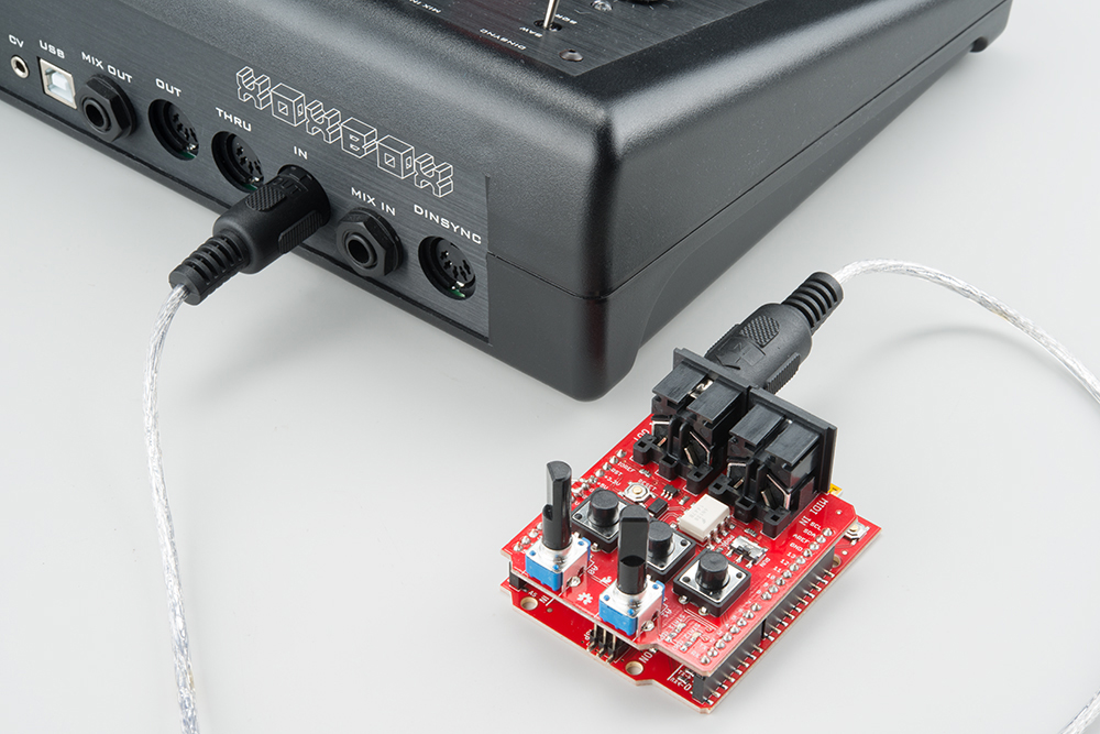
In order for this to work, the x0xb0x needs to be configured to follow incoming clock messages -- on the x0xb0x, this is as simple as setting the mode rotary switch to PATT MIDI SYNC. It follows the tempo, starts and stops properly. However, it doesn't appear to properly obey the continue messages.
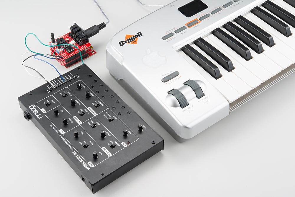
Example #2: MIDI-to-control-voltage
If you're interested in building a MIDI synthesizer, the MIDI Shield is quite capable. There is an example in the Forty Seven Effects documentation that uses the Arduino tone library as a simple MIDI instrument. We're going to build a little more ambitious system, that allows us to play the Moog Werkstatt with real keys. This is useful because the Werkstatt is usually played with an array of tiny tactile switches.
The Werkstatt is a good candidate for this project because it has a header on which it receives external control voltages. We'll be generating the following voltages:
- The pitch control voltage (CV) is a DC voltage that represents which key is currently pressed. The oscillator on the Werkstatt raises its pitch an octave for every volt present on this input; in other words, a semitone is 1/12th of a volt.
- The gate signal is an on/off indicator -- when one or more keys on the MIDI controller are held, the gate is high. When no keys are pressed, the gate is low. The Werkstatt responds to the gate by triggering the envelope generator, which in turn drives the VCF and VCA.
- There's a second analog control voltage from the converter that represents modulation wheel (continuous controller #0) position. It can be patched into other inputs on the Werkstatt, such as LFO rate or filter cutoff.
Materials
This project requires the following parts.
It also needs a MIDI keyboard controller and a MIDI cable.
Construction
Construction and testing is a little more involved that the other two projects.
First, we need a ground wire in the Werkstatt. In this case, a green wire is wrapped around one of the screw posts inside and out through a gap in the front of the chassis.

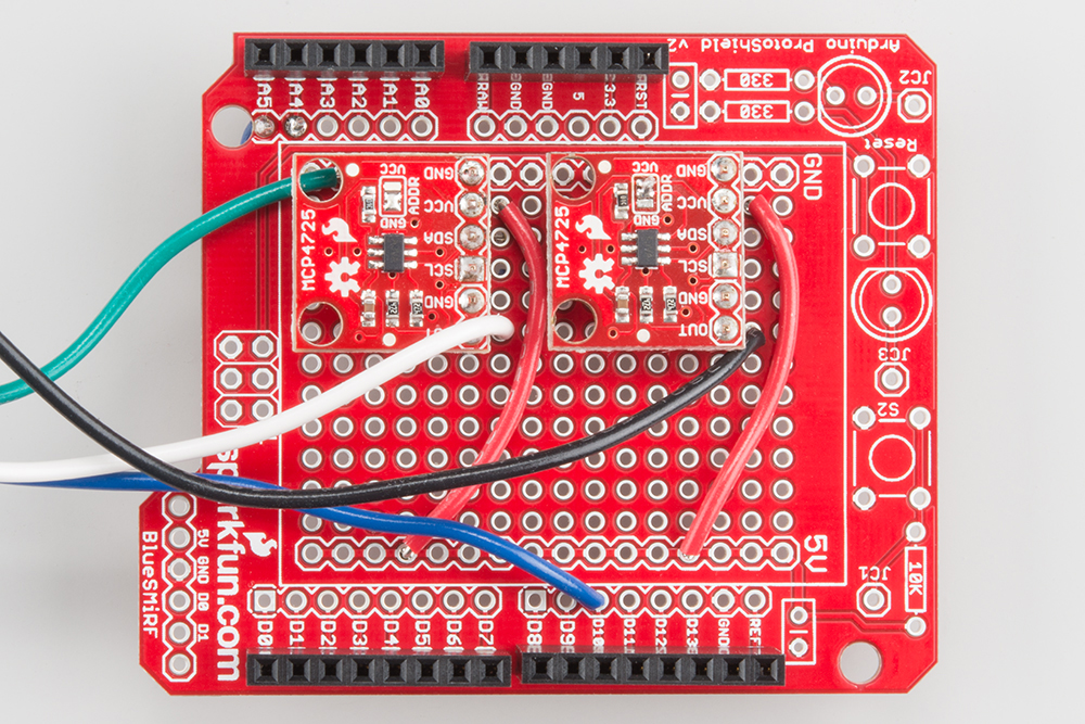
DAC Board Assembly
After that, prepare the DACs, and put them on the proto shield. The DACs come configured using the same I2C address (0x60) -- on one of the DAC breakouts, cut the traces on the pullup resistor jumper on the back of the board, and switch its address to 0x61 by switching the ADDR jumper to VCC.
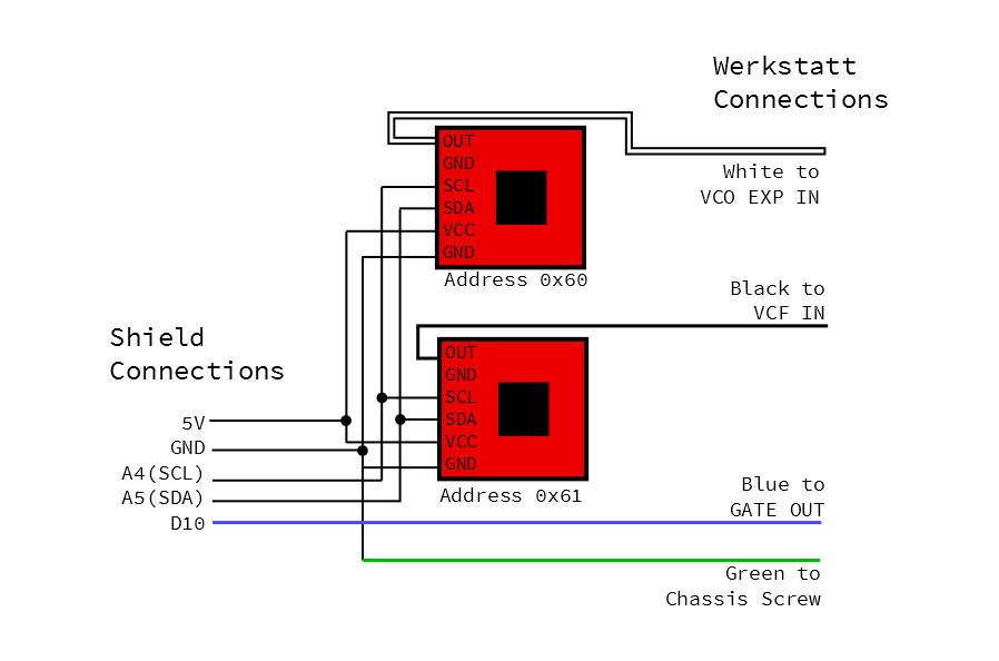
The two DACs are soldered onto strips of breakaway headers and then onto the proto shield. The following connections were made on the shield with wire:
- Their VCC pins were tied to the 5V pin.
- The SDA pins were tied to A4.
- The SCL pins were tied to A5.
- Longer wires were connected to the DAC outputs -- we selected a blue one, a white one, and a black one.
- The white wire is the output of the DAC at the default address.
- The black wire is the output of the other DAC.
- The blue wire was connected to D10.
- The green ground wire from inside the Werkstatt is tied to a
GNDpin on the proto shield.
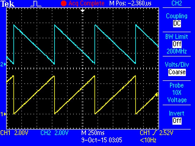
Testing the DACs
Once the DACs are wired onto the protoshield, put the shield on the RedBoard to test them. Loading the DAC Integration Test sketch to verify that they're working. It verifies that they're working correctly and communicating on the correct addresses by generating opposing full-scale sawtooth waves.
Connections
Once you're confident that the DACs are working, you can put the MIDI shield on top of the stack, and connect the Werkstatt and MIDI controller. The MIDI controller is connected to the MIDI input on the shield. The wires from the protoshield are connected to the Werkstatt as follows:
- The white wire gets plugged into the
VCO EXPinput. - The black wire goes into the
VCF IN. - The blue wire is connected to the
GATE OUT.
Firmware
The firmware for this project is a little more complex, requiring ancillary *.CPP and *.H files. Get all three files from the
GitHub folder for the project, and store them in a directory named MIDI-CV. When you open MIDI-CV.ino, it should also open notemap.h and .cpp. Compile and load the sketch, then press some keys on your MIDI controller.
This example uses a more sophisticated interface to the 47 Effects library: rather than polling the library for new messages, it installs callback routines for the relevant message categories. It's also configured to listen in Omni mode - it should respond to messages on any MIDI channel.
In Operation
With a range of 5V to work with, the design target was to have 4 octaves of control voltage, plus roughly +/-1/2 octave bend range. If multiple keys are held, the CV represents the lowest note.
The MIDI-CV sketch includes a fun bonus -- an arpeggiator! If you hold more than one controller key at a time, the converter will periodically cycle between the keys.
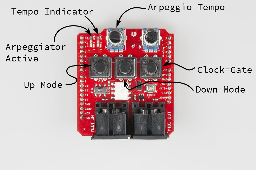
- Button D2 enables the arpeggiator in up mode.
- Button D3 enables the arpeggiator in Down mode.
- Button D4 changes the gate to follow the arpeggiator clock.
- Pot A1 controls the rate of arpeggiation.
- The red LED (D7) displays arpeggiator tempo.
- The green LED (D6) illuminates when the arpeggiator is enabled.
You can switch between up and down modes while the arpeggiator is running. To disable the arpeggiator, press the button for the current mode a second time.
Calibration
The convention for control voltage is that increasing the voltage by one volt will cause the pitch to raise by an octave; 1/12th of a volt (0.08333V) corresponds to a semitone.
The DACs are also referenced to VCC on the board, nominally 5V in this case. Different power supplies will change the scaling of the CV -- the test unit behaved a little differently when powered from the USB connection (yielding VCC of 5.065 V) and from a 9V wall-wart supply plugged into the barrel jack (resulting in VCC of 5.008 V). When you adjust the scaling, it's important that you're powering the system as it will be deployed!
The intonation can be adjusted at both ends of the interface described here. Trimpot VR5 in the Werkstatt allows for Volt-to-Octave adjustments. In the Sketch, the constant DAC_CAL is also used to change the CV scaling. Since it's adjustable at both ends, it can lead to confusion if you start adjusting them at the same time.
The key to preventing that confusion is remembering the Volt/Octave convention. Independently adjust each end of the interface so that volts and octaves correspond. We calibrated the system using the following procedure:
- First the Arduino side is calibrated to produce a 1V step for an octave between note-on messages
- A DC Voltmeter was connected to the CV output of the DAC board.
- Ascending octaves were played on the keyboard.
- The
DAC_CALvalue was adjusted until those octaves resulted in 1VDC changes to the CV output.- In this case, the default value of 6826 worked fairly well.
- The resulting voltages were 0.483V, 1.487V, 2.485V, 3.484V, and 4.485V.
- Once the CV has been adjusted to 1V/8ve, VR5 in the Werkstatt can be adjusted to volt/octave response.
- We used a frequency counter function in an oscilloscope to check the frequency, measured at the
VCO outpatch point. It was doublechecked with a digital guitar tuner. - We started by hopping back and forth between low C and the next C up, then moving to higher octaves as the intonation got better.
- If you tune the high A to 440 Hz, working backwards to the lowest A on a 4-octave keyboard gives you 440 Hz, 220 Hz, 110 Hz and 55 Hz.
- The Werkstatt is most accurate in the lower registers, and tends to run a little flat in the upper registers.
- The tuning pot on the panel is also somewhat touchy. While you're building this interface, you might also consider adding Moog's Fine Tuning Mod.
- We used a frequency counter function in an oscilloscope to check the frequency, measured at the
Troubleshooting
This project was developed using a soft serial port for MIDI and the hardware serial port to print debug messages. Once it was working, the debug printing was disabled, and MIDI was reverted to the hardware serial port.
If you want to enable debug printing:
- Start by adjusting SJ1 and SJ2 for MIDI on the soft serial pins.
- Amend the declaration of the MIDI instance to create and use the soft serial port.
- Change the
VERBOSEmacro to1
Example #3: MIDI Analyzer
Sometimes, when you're developing MIDI code, you want to be able to see the messages being sent on the line. Exactly what values are being sent? Is a byte getting lost somewhere?
If you've got an old toaster Mac sitting around, you can use MIDI Scope, or MIDI Ox on Windows systems.
This example is a MIDI sniffer along those lines. It receives MIDI messages via the library, and interprets them on the serial port.
Hardware Configuration
This sketch requires two serial ports -- one for MIDI communication, and one for printing the interpreted messages. The shield needs to be configured to use a software serial port for the MIDI communications.
The Sketch
/******************************************************************************
MIDI-sniffer.ino
Use SparkFun MIDI Shield as a MIDI data analyzer.

Byron Jacquot, SparkFun Electronics
October 8, 2015
https://github.com/sparkfun/MIDI_Shield/tree/V_1.5/Firmware/MIDI-sniffer

Reads all events arriving over MIDI, and turns them into descriptive text.
If you hold the button on D2, it will switch to display the raw hex values arriving,
which can be useful for viewing incomplete messages and running status.

Resources:

Requires that the MIDI Sheild be configured to use soft serial on pins 8 & 9,
so that debug text can be printed to the hardware serial port.

This code is dependent on the FortySevenEffects MIDI library for Arduino.
https://github.com/FortySevenEffects/arduino_midi_library
This was done using version 4.2, hash fb693e724508cb8a473fa0bf1915101134206c34
This library is now under the MIT license, as well.
You'll need to install that library into the Arduino IDE before compiling.


Development environment specifics:
It was developed for the Arduino Uno compatible SparkFun RedBoard, with a  SparkFun
MIDI Shield.

Written, compiled and loaded with Arduino 1.6.5

This code is released under the [MIT License](http://opensource.org/licenses/MIT).

Please review the LICENSE.md file included with this example. If you have any questions
or concerns with licensing, please contact techsupport@sparkfun.com.

Distributed as-is; no warranty is given.
******************************************************************************/


#include
#include
#include

#define PIN_RAW_INPUT 2

#define PIN_POT_A0 0
#define PIN_POT_A1 1

static const uint16_t DEBOUNCE_COUNT = 50;

// Need to use soft serial, so we can report what's happening
// via messages on hard serial.
SoftwareSerial SoftSerial(8, 9);

/* Args:
   - type of port to use (hard/soft)
   - port object name
   - name for this midi instance
*/
MIDI_CREATE_INSTANCE(SoftwareSerial, SoftSerial, MIDI);
// This doesn't make much sense to use with hardware serial, as it needs
// hard serial to report what it's seeing...

void setup()
{
  // put your setup code here, to run
  once:

  // LED outputs
  Serial.begin(19200);
  Serial.println("Setting up");

  // do I need to init the soft serial port?
  // No - MIDI Lib will do it.

  // We want to receive messages on all channels
  MIDI.begin(MIDI_CHANNEL_OMNI);

  // We also want to echo the input to the output,
  // so the sniffer can be dropped inline when things misbehave.
  MIDI.turnThruOn();

  pinMode(PIN_RAW_INPUT, INPUT_PULLUP);

}

void loop()
{
  static uint8_t  ticks = 0;
  static uint8_t  old_ticks = 0;


  // put your main code here, to run repeatedly:

  if(digitalRead(PIN_RAW_INPUT) == LOW)
  {
    // If you hold button D2 on the shield, we'll print
    // the raw hex values from the MIDI input.
    //
    // This can be useful if you need to troubleshoot issues with
    // running status

    byte input;
    if(SoftSerial.available() != 0)
    {
      input = SoftSerial.read();

      if(input & 0x80)
      {
        Serial.println();
      }
      Serial.print(input, HEX);
      Serial.print(' ');
    }
  }
  else
  {
    // turn the crank...
    if (  MIDI.read())
    {
      switch (MIDI.getType())
      {
        case midi::NoteOff :
          {
            Serial.print("NoteOff, chan: ");
            Serial.print(MIDI.getChannel());
            Serial.print(" Note#: ");
            Serial.print(MIDI.getData1());
            Serial.print(" Vel#: ");
            Serial.println(MIDI.getData2());
          }
          break;
        case midi::NoteOn :
          {
            uint8_t vel;

            Serial.print("NoteOn, chan: ");
            Serial.print(MIDI.getChannel());
            Serial.print(" Note#: ");
            Serial.print(MIDI.getData1());
            Serial.print(" Vel#: ");
            vel = MIDI.getData2();
            Serial.print(vel);
            if (vel == 0)
            {
              Serial.print(" *Implied off*");
            }
            Serial.println();
          }
          break;
        case midi::AfterTouchPoly :
          {
            Serial.print("PolyAT, chan: ");
            Serial.print(MIDI.getChannel());
            Serial.print(" Note#: ");
            Serial.print(MIDI.getData1());
            Serial.print(" AT: ");
            Serial.println(MIDI.getData2());
          }
          break;
        case midi::ControlChange :
          {
            Serial.print("Controller, chan: ");
            Serial.print(MIDI.getChannel());
            Serial.print(" Controller#: ");
            Serial.print(MIDI.getData1());
            Serial.print(" Value: ");
            Serial.println(MIDI.getData2());
          }
          break;
        case midi::ProgramChange :
          {
            Serial.print("PropChange, chan: ");
            Serial.print(MIDI.getChannel());
            Serial.print(" program: ");
            Serial.println(MIDI.getData1());
          }
          break;
        case midi::AfterTouchChannel :
          {
            Serial.print("ChanAT, chan: ");
            Serial.print(MIDI.getChannel());
            Serial.print(" program: ");
            Serial.println(MIDI.getData1());

          }
          break;
        case midi::PitchBend :
          {
            uint16_t val;

            Serial.print("Bend, chan: ");
            Serial.print(MIDI.getChannel());

            // concatenate MSB,LSB
            // LSB is Data1
            val = MIDI.getData2() << 7 | MIDI.getData1();

            Serial.print(" value: 0x");
            Serial.println(val, HEX);


          }
          break;
        case midi::SystemExclusive :
          {
            // Sysex is special.
            // could contain very long data...
            // the data bytes form the length of the message,
            // with data contained in array member
            uint16_t length;
            const uint8_t  * data_p;

            Serial.print("SysEx, chan: ");
            Serial.print(MIDI.getChannel());
            length = MIDI.getSysExArrayLength();

            Serial.print(" Data: 0x");
            data_p = MIDI.getSysExArray();
            for (uint16_t idx = 0; idx < length; idx++)
            {
              Serial.print(data_p[idx], HEX);
              Serial.print(" 0x");
            }
            Serial.println();
          }
          break;
        case midi::TimeCodeQuarterFrame :
          {
            // MTC is also special...
            // 1 byte of data carries 3 bits of field info
            //      and 4 bits of data (sent as MS and LS nybbles)
            // It takes 2 messages to send each TC field,

            Serial.print("TC 1/4Frame, type: ");
            Serial.print(MIDI.getData1() >> 4);
            Serial.print("Data nybble: ");
            Serial.println(MIDI.getData1() & 0x0f);
          }
          break;
        case midi::SongPosition :
          {
            // Data is the number of elapsed sixteenth notes into the song, set as
            // 7 seven-bit values, LSB, then MSB.

            Serial.print("SongPosition ");
            Serial.println(MIDI.getData2() << 7 | MIDI.getData1());
          }
          break;
        case midi::SongSelect :
          {
            Serial.print("SongSelect ");
            Serial.println(MIDI.getData1());
          }
          break;
        case midi::TuneRequest :
          {
            Serial.println("Tune Request");
          }
          break;
        case midi::Clock :
          {
            ticks++;

            Serial.print("Clock ");
            Serial.println(ticks);
          }
          break;
        case midi::Start :
          {
            ticks = 0;
            Serial.println("Starting");
          }
          break;
        case midi::Continue :
          {
            ticks = old_ticks;
            Serial.println("continuing");
          }
          break;
        case midi::Stop :
          {
            old_ticks = ticks;
            Serial.println("Stopping");
          }
          break;
        case midi::ActiveSensing :
          {
            Serial.println("ActiveSense");
          }
          break;
        case midi::SystemReset :
          {
            Serial.println("Stopping");
          }
          break;
        case midi::InvalidType :
          {
            Serial.println("Invalid Type");
          }
          break;
        default:
          {
            Serial.println();
          }
          break;
      }
    }
  }
}
The library instantiation has a couple of specific details worth noting:
- It uses a software serial port on pins 8 and 9. This leaves the regular serial port available for displaying the output messages.
- It enables the soft-thru feature of the library, so it retransmits the messages it receives. We can insert the sniffer between two other devices without breaking the link.
To use this code:
- Load the sketch
- Connect the MIDI Shield inline, between other MIDI devices
- Start a terminal application at 19200 baud.
- Send MIDI message & observe the output on the terminal.
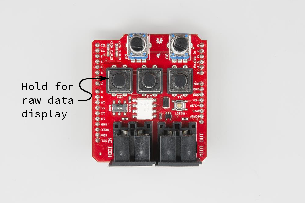
This sniffer has a hidden feature: if you hold down the D2 button on the shield, it will read and display the raw bytes from the serial port, rather than the output of the MIDI library.
In Use
As a test, the sniffer was connected to a MIDI keyboard, and notes were occasionally pressed and released. In the screen capture that follows, the first few lines are shown in "cooked" format, and the next few are in "raw" format. We learn something interesting from the raw values.
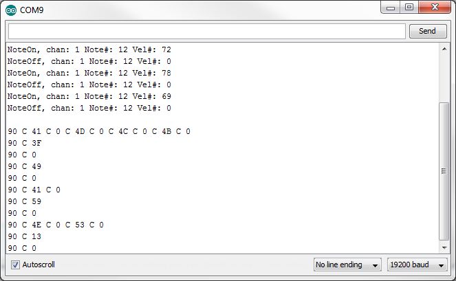
The first few messages are note on and off pairs for low C on the keyboard. It turns on, it turns off.
Then the "raw mode" button is held, and the key is pressed a few more times. The first few articulations are somewhat rapid, the next few are a bit slower. The display moves to a new line for each new status byte received.
You'll notice that the rapid articulations are sent using a single status byte (0x90), followed by pairs of data bytes (0xC, 0x41, then 0xC, 0x0, etc ). The controller is using running status to reduce the number of bytes sent, and using note on with velocity of 0 to take advantage of running status. The next few lines in the trace are the same articulation of low C, just played more slowly. Each articulation gets a status byte (0x90), followed by two data bytes. Even without running status, it's still using note-on with velocity of 0, instead of note-off status bytes.
We have learned that this controller uses running status when the same message is sent in rapid succession, but sends fresh status bytes when the messages occur more slowly. The threshold for using running status seems to be somewhere at around 1/2 of a second.
Resources and Going Further
Resources
- If you need more detailed background information about MIDI, check out our MIDI Tutorial.
- The MIDI Specification is maintained by the MIDI Manufacturer's Organization.
- More information about the MCP4725 digital-to-analog converter can be found in this hookup guide
Going Further
- The WAV Trigger implements MIDI on it's serial port, allowing you to control up to 2048 velocity-sensitive samples.
- If the shield form-factor isn't right for you, we also sell the MIDI Connector all by itself.
- The latest revision of the Bleep Drum kit now includes a MIDI input
- Hairless MIDI allows you to open a virtual MIDI port over a standard serial bridge (like an FTDI adapter).