MIDI Shield Hookup Guide
 Byron J.
Configuration
The MIDI Shield has a number of solder jumpers on the bottom side, so that it can be customized for different situations.
Hardware vs. Software Serial Port
The first set of jumpers are SJ1 and SJ2, near digital pins 10-13. These allow you to swap between the hardware serial port on pins D0 and D1, or a software serial port on pins 8 and 9.
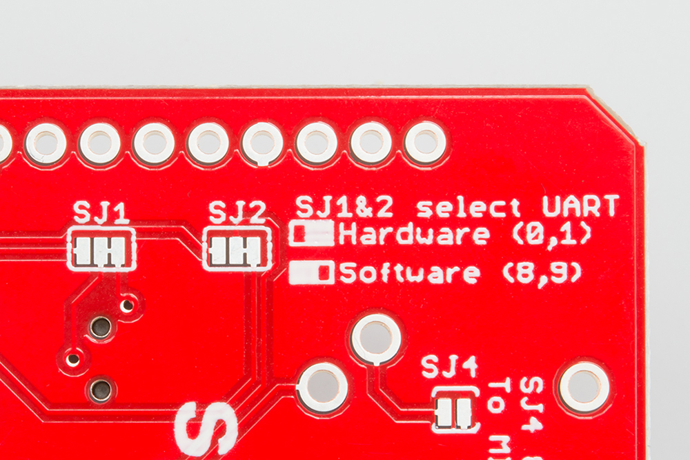
By default, these are connected with a copper trace between the center and right-hand pads, selecting the hardware UART. If you'd rather use the software serial port, cut that trace using a hobby knife, and flow some solder the bridge the center pad to the left one.
Why would you want to do this? A couple of reasons jump to mind.
- If you're using the software serial port for MIDI, the hardware port is still available to the bootloader. You don't need to toggle the RUN/PROG switch every time you try to load.
- The hardware serial port is still available for other communication. In particular, you can use
Serial.print()statements to debug your code.
MIDI Out or Thru
SJ3 is on the bottom of the board, near the center.
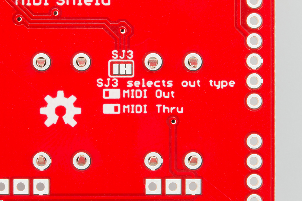
It allows the MIDI output port to be repurposed as a MIDI thru. Instead of being tied to the TX line of the selected serial port, the MIDI out jack will retransmit a copy of bytes that arrive at the input. If you don't need the MIDI output to transmit data, MIDI thru might be useful, especially if you're daisy chaining MIDI devices.
Like the serial port selection jumpers, the default path is connected with a copper trace. If you want to switch the jumper, cut the trace, and bridge the other two pads with solder.
The MIDI library we'll be using also has the option to enable software thru functionality.
Power Over MIDI
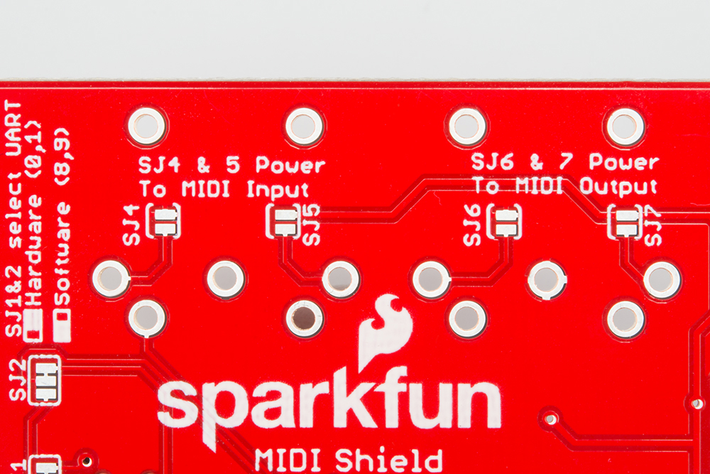
The final set of jumpers is SJ4, 5, 6 and 7. These are under the MIDI ports and implement for a form of power-over-MIDI.
Power over MIDI isn't actually defined by the MIDI Standard, and a number of manufacturers have proposed and implemented different schemes for providing power to a device over the MIDI cable.
There isn't much agreement on how this is implemented. Some vendors add two extra pins, using a 7-pin connector. Some vendors simply sip a tiny bit of current off pin 4, and some use the pins that are otherwise not used in standard. Similarly, the voltage available differs -- it might be 5 VDC, 12 VDC, or sometimes even 12 VAC!
Since Arduinos don't have a 12 VDC supply, the MIDI shield allows you to route 5V to the unused pins of the 5-pin DIN connector: pin 1 is tied to 5V, and pin 3 gets grounded. This is mainly useful if you want to use a pair of MIDI shields to build a system with a subordinate device (like a MIDI enabled footpedal) that is powered by the larger system it's connected to.
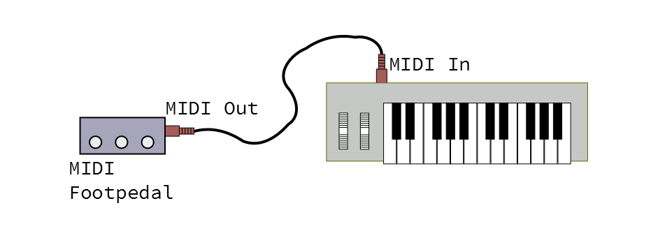
In a configuration like this, the shield on the pedal end would have the jumpers on the output closed (SJ6 and 7), and the shield on the host system end would have the input jumpers closed (SJ4 and 5).
This configuration allows you to power one MIDI Shield from another, but it may not be interoperable with other gear. Carefully consult the user manual of other devices before connecting them. Additionally, it requires a cable that has all five pins connected. The average MIDI cable has no connections to pins 1 and 3; sometimes MIDI cables are sold as having all five pins connected, and sometimes such a cable is simply sold as a "five pin DIN" cable.
There are some other technical concerns when powering devices over MIDI.
- It's most useful when the power provider and recipient are designed as a system. It's hard to make power over MIDI universally applicable, because you need to be able to anticipate voltage and current requirements.
- The original MIDI hardware implementation uses optocouplers to avoid ground loops. Power over MIDI invites ground loop-related problems by tying the grounds of different devices together.