MIDI Shield Hookup Guide
 Byron J.
Assembly
Before assembling your MIDI shield, consider how you're going to use it. If you don't need buttons and potentiometers, you can leave them off. Similarly, if you only need the MIDI input or output port, you can leave the other port off. Finally, there are a couple of options for headers -- you can select headers that fit your application.
Materials
The MIDI shield kit contains the following parts.
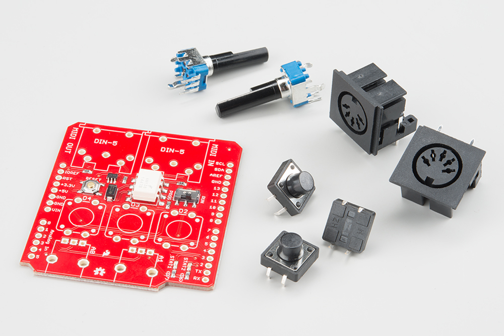
- The MIDI Shield PCB
- 2x 5-pin DIN conectors
- 2x 10K rotary potentiometer
- 3x 12mm tactile pushbutton switches
You'll also need to select headers that fit your application.
- You can use the R3 stackable header kit, but they're a bit tall and make the buttons hard to reach.
- If you're using an Arduino board that predates R3, such as the Arduino Pro, you can use the regular stackable header kit.
- Alternately, you can use regular snappable headers, which don't stick as far above the board, leaving plenty of room to access the switches and potentiometers.

Tools
The following tools are recommended.
- A soldering iron with a fine-point tip.
- Some solder, either leaded or lead-free.
- A magnifying glass or loupe.
- A vise to hold the PCB as you work.
Building The MIDI Shield
If you're using stackable headers, they're easiest to put on at the very beginning (if you're using the snappable headers, we'll save them until the end). To install the stackable headers, put them through the board from the top side
Then flip the board over so it's supported by the bodies of the headers. Adjust the alignment until the headers stand squarely in your work surface, and solder them in place.
Next, we'll install the components on the top of the board in order from the shortest to the tallest. We'll start with the pushbuttons -- snap them through the holes, then solder them in place.

Following that, install the MIDI jacks, taking care to keep them seated to the PCB while you solder.
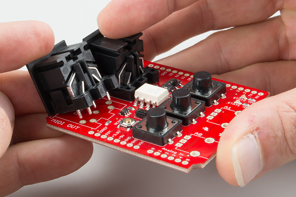
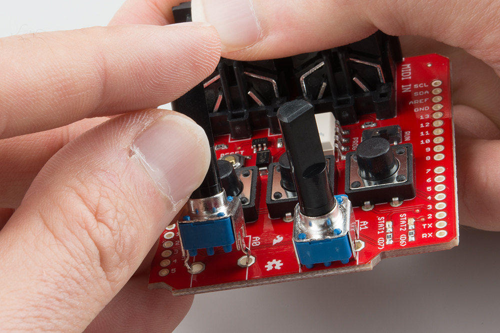
As the tallest component, the potentiometers go on next. Getting them into the PCB can take some effort -- you might need to nudge the tabs a little bit to get them through the board. Before you solder, doublecheck that the shafts are perpendicular to the surface of the board, because it takes a lot of desoldering effort to straighten them if they're crooked.
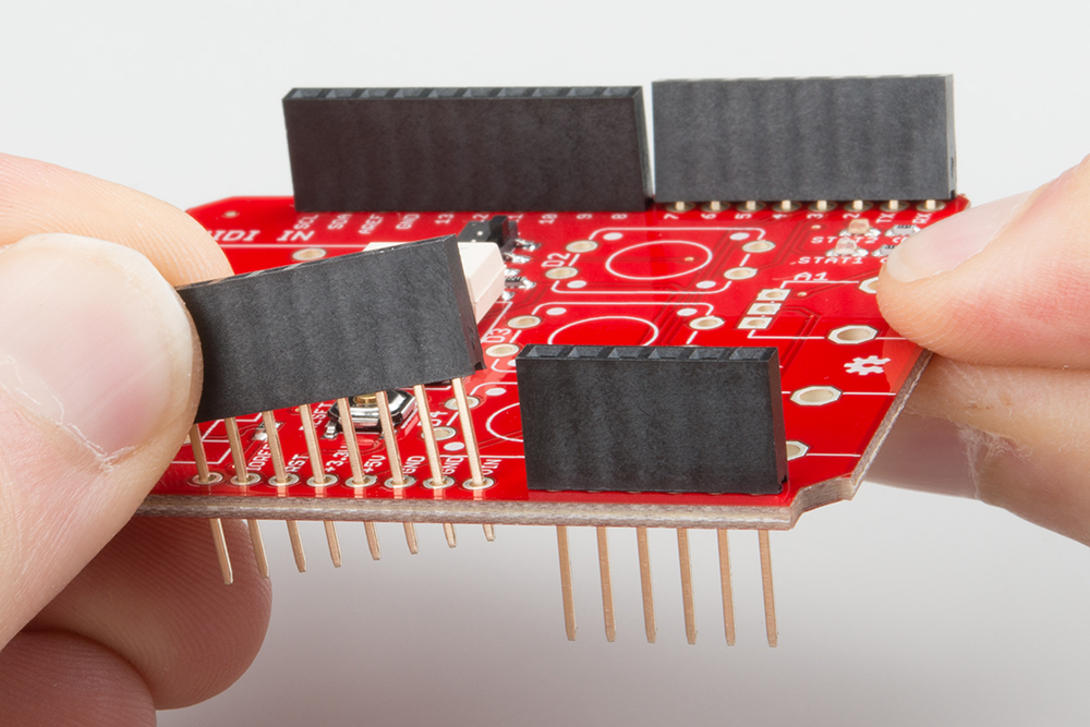
Finally, if you're using snappable headers instead of the stacking ones, install them. It's easiest if you use an Arduino board as an assembly jig. Snap the headers into suitable lengths (6, 8, 8 and 10 for an R3 board), and push them into the sockets on the Arduino. Then lay the MIDI shield PCB over them, as shown below.
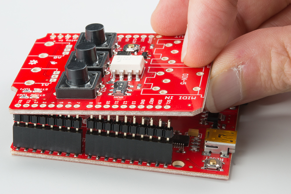
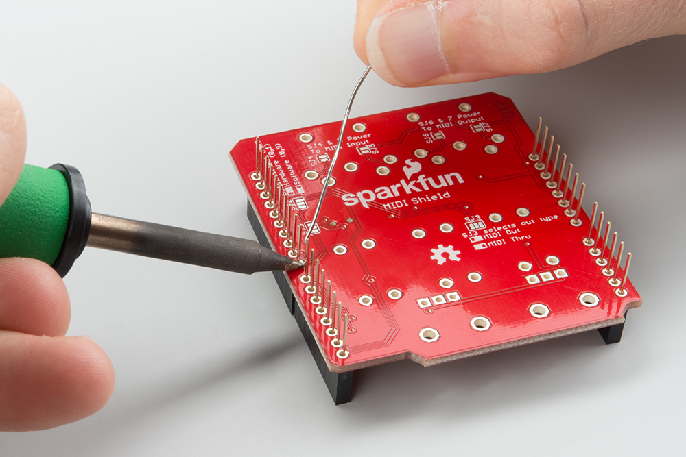
Solder them from the top of the board.
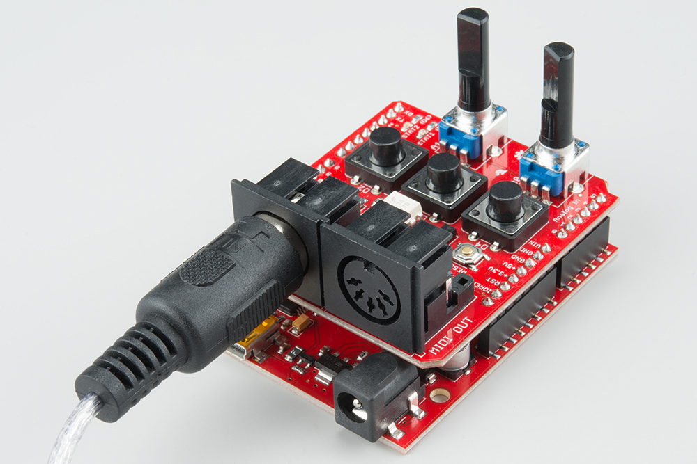
In Operation
One it's assembled, place the MIDI shield on top of your Arduino, then connect your MIDI devices to the ports.
RUN vs. PROG
There's one last thing to mention: near the MIDI input jack is a small slide switch.
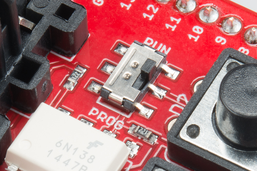
By default, the shield uses the hardware serial port on the Arduino for MIDI communication -- but that port is shared with the bootloader, which is initiated when you press the "load" button in the Arduino IDE. The switch allows them to share the port politely, avoiding output contention.
If you're using the hardware serial port, set the switch to the PROG position, before you load your sketch. Once it's loaded and verified, set it back to RUN.
In the next section we'll discuss using a software serial port. One advantage of software serial is that you don't need to remember to flip the switch every time you load!