MIDI Shield Hookup Guide
 Byron J.
Example #1: Clock Generator & Receiver
The first example we'll demonstrate is synchronizing multiple devices using MIDI clock commands.
For this example, we'll be building two different variants of the clock code. The first variant is the master clock, which generates periodic MIDI timing clock (0xF8) bytes, and start(0xFA), stop (0xFC), and continue (0xFB) messages. These messages are used to transmit musical timing from one device to another, acting as a high resolution metronome.

The other end of the link listens for those messages and responds to them.
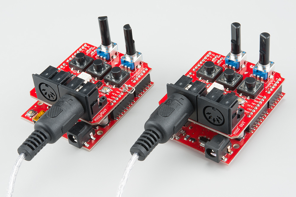
For this demonstration, we'll be using a pair of RedBoards, each with a MIDI shield. You can substitute either end of the link for a device that implements MIDI clock, as we'll show below.
The Firmware
Each of these boards gets loaded with a different sketch. The master clock will get loaded with the clock-gen.ino sketch.
/******************************************************************************
clock-gen.ino
Use SparkFun MIDI Shield as a MIDI clock generator.

Byron Jacquot, SparkFun Electronics
October 8, 2015
https://github.com/sparkfun/MIDI_Shield/tree/V_1.5/Firmware/clock-gen

Generate MIDI clock messages at the tempo indicated by  A1.
Send start/stop messages when D2 is pressed, and continue when D3 is pressed.

Resources:

  This sketch has a clock receiving counterpart in clock-recv.ino

  This code is dependent on the FortySevenEffects MIDI library for Arduino.
  https://github.com/FortySevenEffects/arduino_midi_library
  This was done using version 4.2, hash fb693e724508cb8a473fa0bf1915101134206c34
  This library is now under the MIT license, as well.
  You'll need to install that library into the Arduino IDE before compiling.


Development environment specifics:
  It was developed for the Arduino Uno compatible SparkFun RedBoard, with a  SparkFun
  MIDI Shield.

  Written, compiled and loaded with Arduino 1.6.5

This code is released under the [MIT License](http://opensource.org/licenses/MIT).

Please review the LICENSE.md file included with this example. If you have any questions
or concerns with licensing, please contact techsupport@sparkfun.com.

Distributed as-is; no warranty is given.
******************************************************************************/

#include
#include
#include

#define PIN_LED_PLAYING 6
#define PIN_LED_TEMPO 7
#define PIN_PLAY_INPUT 2
#define PIN_CONTINUE_INPUT 3

#define PIN_TEMPO_POT 1

static const uint16_t DEBOUNCE_COUNT = 50;

//SoftwareSerial SoftSerial(8,9);

/* Args:
   - type of port to use (hard/soft)
   - port object name
   - name for this midi instance
*/
MIDI_CREATE_INSTANCE(HardwareSerial, Serial, MIDI);
//MIDI_CREATE_INSTANCE(SoftwareSerial, SoftSerial, MIDI);

bool running;
bool send_start;
bool send_stop;
bool send_continue;
bool send_tick;
uint32_t tempo_delay;


void play_button_event()
{
  // toggle running state,
  // send corresponding responses
  running = !running;

    if(running)
    {
      send_start = true;
      digitalWrite(PIN_LED_PLAYING, LOW);
    }
    else
    {
      send_stop = true;
      digitalWrite(PIN_LED_PLAYING, HIGH);
    }
}

void cont_button_event()
{
  // ignore continue if running
  if(!running)
  {
    send_continue = true;
    running = true;
    digitalWrite(PIN_LED_PLAYING, LOW);
  }
}

void timer_callback()
{
  send_tick = true;
}

void check_pots()
{
  uint32_t pot_val;
  uint32_t calc;

  pot_val = analogRead(PIN_TEMPO_POT);

  // Result is 10 bits
  calc = (((0x3ff - pot_val) * 75)/1023) + 8;

  tempo_delay = calc  ;//* 5;
}

void check_buttons()
{
  uint8_t val;
  static uint16_t play_debounce = 0;
  static uint16_t cont_debounce = 0;

  // First the PLAY/STOP button
  val = digitalRead(PIN_PLAY_INPUT);

  if(val == LOW)
  {
    play_debounce++;

    if(play_debounce == DEBOUNCE_COUNT)
    {
      play_button_event();
    }
  }
  else
  {
    play_debounce = 0;
  }

  // Then the continue button
  val = digitalRead(PIN_CONTINUE_INPUT);

  if(val == LOW)
  {
    cont_debounce++;

    if(cont_debounce == DEBOUNCE_COUNT)
    {
      cont_button_event();
    }
  }
  else
  {
    cont_debounce = 0;
  }


}


void setup()
{
  // put your setup code here, to run once:

  // LED outputs
  pinMode(PIN_LED_PLAYING, OUTPUT);
  pinMode(PIN_LED_TEMPO, OUTPUT);
  digitalWrite(PIN_LED_PLAYING, HIGH);
  digitalWrite(PIN_LED_TEMPO, HIGH);

  // button inputs
  pinMode(PIN_PLAY_INPUT, INPUT_PULLUP);
  pinMode(PIN_CONTINUE_INPUT, INPUT_PULLUP);

//  Serial.begin(9600);
//  Serial.println("Setting up");

//  SoftSerial.begin(31250);

  // do I need to init the soft serial port?

#if 1
  MIDI.begin(MIDI_CHANNEL_OMNI);
  MIDI.turnThruOff();
#endif

  running = false;
  send_start = false;
  send_stop = false;
  send_tick = false;

  // prime the tempo pump
  check_pots();

//  check_timing();

  MsTimer2::set(tempo_delay, timer_callback);
  MsTimer2::start();

}

void loop()
{
  static uint32_t loops = 0;
  static uint8_t  ticks = 0;
  static uint8_t  prev_ticks = 0;
  bool reset_timer = false;

  // put your main code here, to run repeatedly:

  // turn the crank...
  MIDI.read();

  // Check buttons
  check_buttons();

  // process inputs
  if(send_start)
  {
    MIDI.sendRealTime(MIDI_NAMESPACE::Start);
    send_start = false;
//    Serial.println("Starting");

    ticks = 0;

    // Next tick comes immediately...
    // it also resets the timer
    send_tick = true;

  }
  if(send_continue)
  {
    MIDI.sendRealTime(MIDI_NAMESPACE::Continue);
    send_continue = false;
//    Serial.println("continuing");

    // Restore the LED blink counter
    ticks = prev_ticks;

    // Next tick comes immediately...
    // it also resets the timer
    send_tick = true;
  }

  if(send_stop)
  {
    MIDI.sendRealTime(MIDI_NAMESPACE::Stop);
    send_stop = false;
    prev_ticks = ticks ;
//    Serial.println("Stopping");
  }

  if(send_tick)
  {
    MIDI.sendRealTime(MIDI_NAMESPACE::Clock);
    send_tick = false;

    ticks++;
    if(ticks < 6)
    {
      digitalWrite(PIN_LED_TEMPO, LOW);
    }
    else if(ticks == 6)
    {
      digitalWrite(PIN_LED_TEMPO, HIGH);
    }
    else if(ticks >= 24)
    {
      ticks = 0;
    }

    check_pots();

    reset_timer = true;
  }

  if(reset_timer)
  {
    MsTimer2::stop();
    MsTimer2::set(tempo_delay, timer_callback);
    MsTimer2::start();

    reset_timer = false;
  }

  loops++;
}
The clock chasing board is loaded with the clock-recv.ino sketch.
/******************************************************************************
clock-recv.ino
Use SparkFun MIDI Shield as a MIDI clock receiver.

Byron Jacquot, SparkFun Electronics
October 8, 2015
https://github.com/sparkfun/MIDI_Shield/tree/V_1.5/Firmware/clock-recv

Listenn for clock/start/stop/continue messages on the MIDI input

Resources:

  This sketch has a clock generating counterpart in clock-gen.ino

  This code is dependent on the FortySevenEffects MIDI library for Arduino.
  https://github.com/FortySevenEffects/arduino_midi_library
  This was done using version 4.2, hash fb693e724508cb8a473fa0bf1915101134206c34
  This library is now under the MIT license, as well.
  You'll need to install that library into the Arduino IDE before compiling.


Development environment specifics:
  It was developed for the Arduino Uno compatible SparkFun RedBoard, with a  SparkFun
  MIDI Shield.

  Written, compiled and loaded with Arduino 1.6.5

This code is released under the [MIT License](http://opensource.org/licenses/MIT).

Please review the LICENSE.md file included with this example. If you have any questions
or concerns with licensing, please contact techsupport@sparkfun.com.

Distributed as-is; no warranty is given.
******************************************************************************/
#include
#include
#include

#define PIN_LED_PLAYING 6
#define PIN_LED_TEMPO 7
#define PIN_PLAY_INPUT 2
#define PIN_CONTINUE_INPUT 3

#define PIN_TEMPO_POT 1

static const uint16_t DEBOUNCE_COUNT = 50;

//SoftwareSerial SoftSerial(8,9);

/* Args:
   - type of port to use (hard/soft)
   - port object name
   - name for this midi instance
*/
//MIDI_CREATE_INSTANCE(SoftwareSerial, SoftSerial, MIDI);
MIDI_CREATE_INSTANCE(HardwareSerial, Serial, MIDI);

void setup()
{
  // put your setup code here, to run once:

  // LED outputs
  pinMode(PIN_LED_PLAYING, OUTPUT);
  pinMode(PIN_LED_TEMPO, OUTPUT);
  digitalWrite(PIN_LED_PLAYING, HIGH);
  digitalWrite(PIN_LED_TEMPO, HIGH);

  // button inputs
//  Serial.begin(9600);
//  Serial.println("Setting up");

  //  SoftSerial.begin(31250);
  // do I need to init the soft serial port?
  // No - MIDI will do it.

#if 1
  MIDI.begin(MIDI_CHANNEL_OMNI);
  MIDI.turnThruOff();
#endif

}

void loop()
{
  static uint32_t loops = 0;
  static uint8_t  ticks = 0;
  static uint8_t  prev_ticks = 0;

  // put your main code here, to run repeatedly:

  // turn the crank...
  if(  MIDI.read())
  {
    switch(MIDI.getType())
    {
      case midi::Clock :
      {
        ticks++;

        //Serial.print('.');
//        Serial.println(ticks);

        if(ticks < 6)
        {
          digitalWrite(PIN_LED_TEMPO, LOW);
          //Serial.print('#');
        }
        else if(ticks == 6)
        {
          digitalWrite(PIN_LED_TEMPO, HIGH);
        }
        else if(ticks >= 24)
        {
          ticks = 0;
//          Serial.print('\n');
        }
      }
      break;

      case midi::Start :
      {
        digitalWrite(PIN_LED_PLAYING, LOW);
        ticks = 0;
//        Serial.println("Starting");
      }
      break;

      case midi::Stop :
      {
        digitalWrite(PIN_LED_PLAYING, HIGH);
        prev_ticks = ticks;
//        Serial.println("Stopping");
      }
      break;
      case midi::Continue :
      {

        digitalWrite(PIN_LED_PLAYING, LOW);

        // Restore the LED blink counter
        ticks = prev_ticks;
//        Serial.println("continuing");
      }
      break;

      default:
      break;
    }
  }

  loops++;
}
Controls
Before we test the system, lets review how the sketches use the extra I/O on the MIDI shield.
The clock generator uses the following controls:

- The A1 pot controls the tempo.
- The button on D2 acts as a start/stop button.
- The button on D3 is a continue button
The LEDs on both ends of the link serve the same functions.
- D7, the red LED, blinks in time, indicating the tempo.
- D6, the green LED, is illuminated when the system is running.
Testing
Once both boards are loaded, the red (D7) LED on the generator should be blinking, and the receiver should be dark. Connect the MIDI Out of the generator to the MIDI In of the receiver, and its red LED should start blinking. The blink rates will be the same, but they may be skewed relative to each other, not yet in perfect sync.
Now, press the play button on the generator. The green LEDs on both boards should illuminate, and the red LEDs should now blink in synch with each other.
You can adjust the A1 potentiometer to speed up and slow down the tempo. The blink rate will change, and both units will stay in sync as it is adjusted.
The continue button has some special behavior. MIDI defines Start (0xFA) as instructing recipients to reset to the beginning of the song, then start playing. Continue (0xFB) omits the reset, and starts from whereever it was last stopped.
With Other Devices
We can replace either end of the chain with other devices. For purposes of demonstration, we'll be using a Willzyx x0xb0x, an analog synthesizer with an onboard sequencer. The x0xb0x is connected as a receiver.
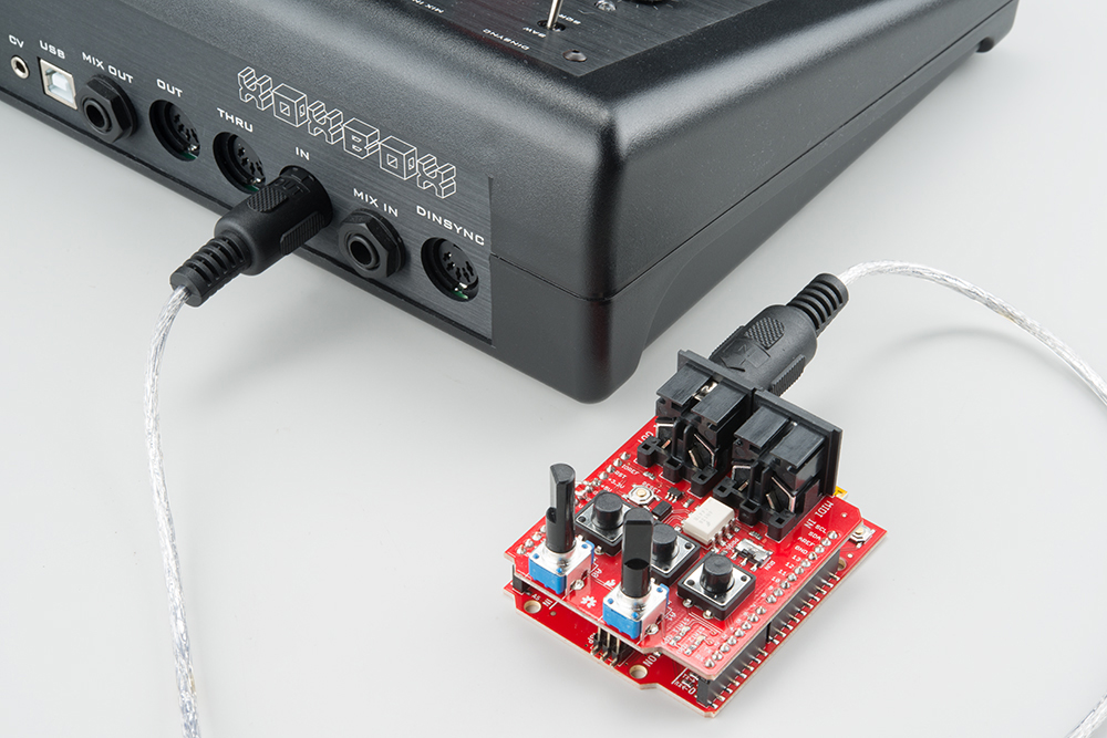
In order for this to work, the x0xb0x needs to be configured to follow incoming clock messages -- on the x0xb0x, this is as simple as setting the mode rotary switch to PATT MIDI SYNC. It follows the tempo, starts and stops properly. However, it doesn't appear to properly obey the continue messages.