TeensyView Hookup Guide
Introduction
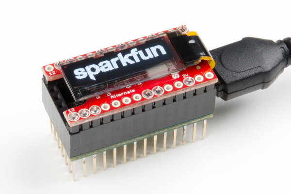
The TeensyView is an SSD1306 128x32 OLED screen breakout that matches the Teensy 3 form factor. It's great for displaying debug information and visualizing data on a Teensy, and it is compatible with the LC, 3.1, 3.2, 3.5, 3.6, Audio Board, Prop Shield, Prop Shield LC and XBee Adapter.
This guide shows how to connect the TeensyView to various Teensy-related products, then shows some examples with a library reference. The SSD1306 driver is quite popular and has a lot of support behind it. The TeensyView Arduino Library is like the Micro OLED Breakout's and the MicroView's libraries, so expect the same functions to work, just tuned for the Teensy and conveniently packaged.
Required Materials
To get started, you'll need the following things:
- A Teensy LC / 3.1 or higher
- A TeensyView
- A soldering iron and soldering tools
- A pair of scissors
- Your option of connecting headers
- Normal Female Headers
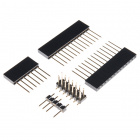
- Stackable headers, such as the Teensy Header Kit
- Break Away Headers --- Straight
- Long Break Away Headers
- An add-on board such as the Audio Board or Prop Shield can be handy to run the examples with
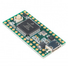
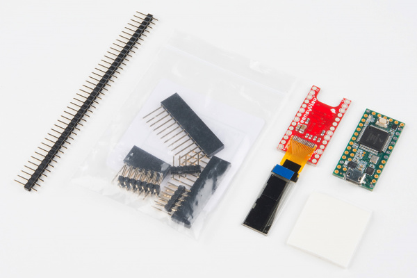
This guide uses a Teensy 3.2, Straight Break Away Headers and a Teensy Header Kit.
Teensy 3.2
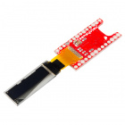
DEV-13736SparkFun TeensyView
LCD-14048Suggested Reading
If you aren't familiar with the following concepts, we recommend checking out these tutorials before continuing.
How to Solder: Through-Hole Soldering
Installing an Arduino Library
Installing Arduino IDE
Hardware Overview and Assembly
The hardware comes as a headerless PCB with OLED soldered on. There are jumpers on one side to configure how the OLED communicates with the attached Teensy. You'll need to set the jumpers, solder the TeensyView to the Teensy or to headers, then affix the OLED.
This section instructs the use of male headers on the TeensyView, with stackable headers on the Teensy.
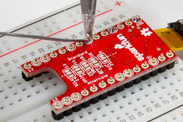
The TeensyView has two available connections for the OLED communication lines, to allow compatibility with various boards. One side (factory configuration/'Standard') is all connected by copper jumpers, with the 'Alternate' side available to reconfigure the connections.
Use this table to determine which pins to use for the TeensyView, or leave them set by copper to the standard pins if no other resources are in use.
Jumper Default Copper Jumpers
(Standard)Audio Board Compatible
(Alternate)Prop Shield Compatible RST 15 2 15 (Std.) D/C 5 21 21 (Alt.) CS 10 20 20 (Alt.) SCLK 13 14 13 (Std.) DATA 11 7 11 (Std.) If necessary, carefully cut the copper jumper on the board and apply solder to reroute the signal.
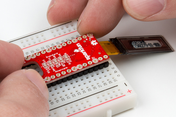
Cutting the copper traces: Make two cuts, one on each end of the copper link, then remove the excess copper with a slight twist of the knife. Solder connections are not shown here, but if you remove the copper link you will need to apply a solder jump between two of the pads of the jumper!Separate two 14-pin lengths of straight male header and fit them into the breadboard, then set the PCB onto them with the jumpers facing up and the LCD facing down. The LCD will fold over and cover the jumpers.
Notice that the OLED is soldered to the back side and folds around the edge of the PCB, covering the selection jumpers. This is so the jumpers can still be accessed if the TeensyView is more permanently attached to a Teensy.Next, solder the headers onto the TeensyView using a flux core solder. The silkscreen rings denote pins that are electrically connected to the TeensyView circuitry. You can choose to either solder all pins, for better mechanical stability, or just the connected pins, if you foresee removal of the pins in the future. This board is assumed to be the top of a stack and may not need all of the Teensy's signals passing through.
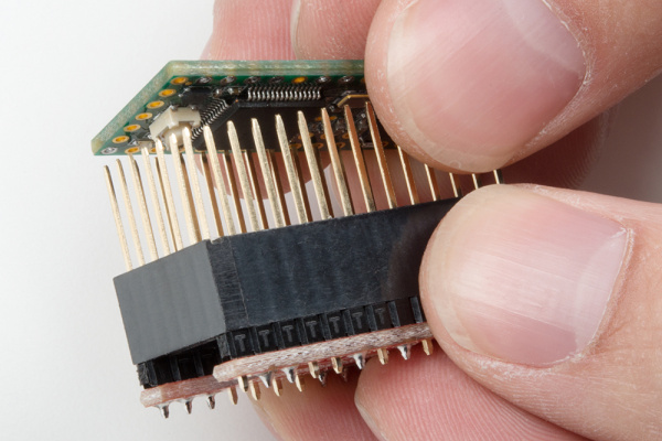
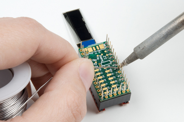
Attaching the straight headers to the Teensy using a breadboard.Note: There are 12x silkscreen rings highlighted. You will only be using 5x of the standard pins and 2x for power on the Teensy as shown earlier in the table of the jumpers. 5x of the remaining pins are the alternate pin connections.Now that the TeensyView has headers, it can be used to help keep the Teensy Stackable Headers in place for assembly. Put the 6 long and two 13 long headers onto the TeensyView, then place the Teensy on and apply solder.
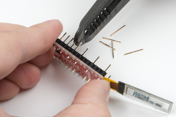
Using the TeensyView as a soldering jigAttaching the Teensy Header KitIf you've decided to only solder the electrically connected pins, now's a good time to pull the spare pins. Hold the TeensyView firmly with one hand and give a steady pull with pliers or wire strippers. To double check, there should only be pins left in the holes with silkscreen rings.
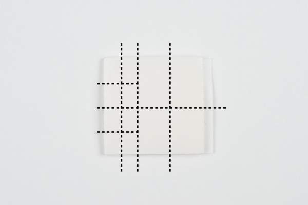
Pulling the pinsApply the screen using the double-sided foam. It's best to start with little pieces until you're sure of the configuration you would like. Visualize how the foam will be divided or draw on it with a pen. Then use your scissors to cut off strips, and subdivide from there.
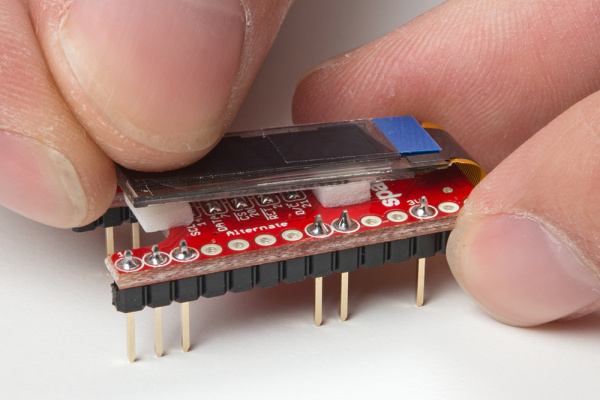
A way to divide the square of foam tapeA couple small pieces go a long way to keep it in place, while a large piece can keep it there on a more permanent basis. Reasons to remove the screen may be to adjust left-right justification (to match a chassis cutout, for example) or to change the configuration of the pins. It can be tempting to just start with a large piece, but don't! The foam is extremely grippy once it's set.
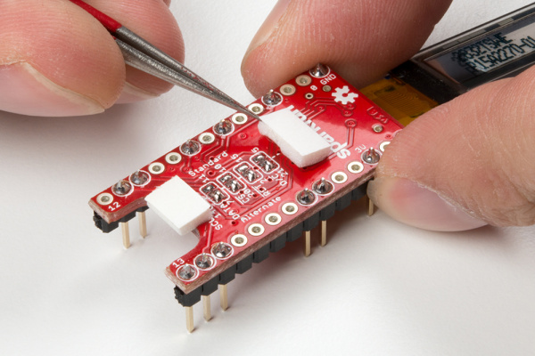
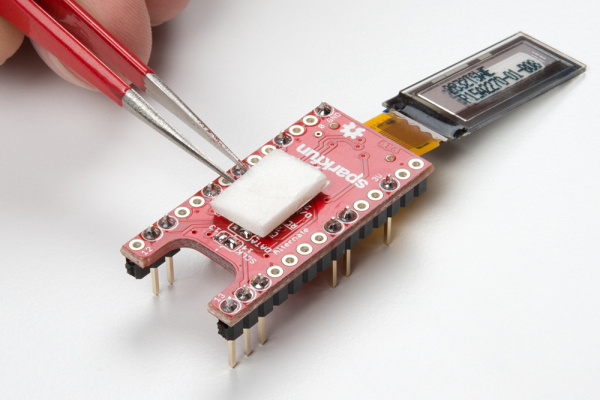
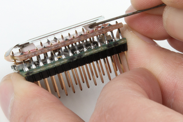
Two small pieces keep the screen from flopping around. A large piece can be used as a permanent solution. Carefully set down the glass.Oh no! You've put your screen down too early and need to adjust something! Don't worry, but don't just pry up the glass either. Use a thin, blunt tool to push the meat of the foam out from the side.
Breaking the foam structure without applying force to the OLED glass.Attach the TeensyView and USB cable. Then run the examples. The TeensyView has a few pins (labeled
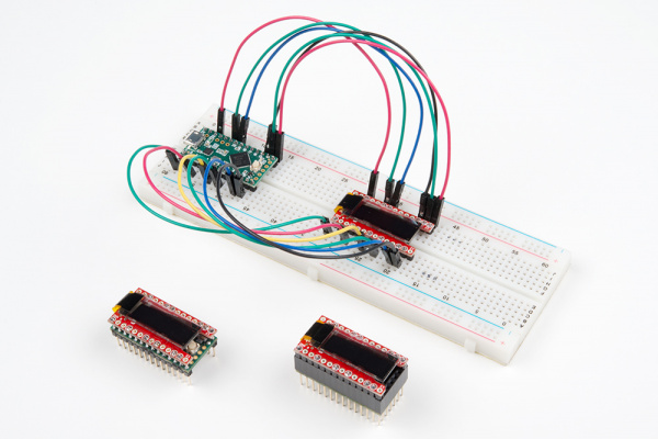
0,13,14,3VandGND) to help make sure it's oriented the right way. Here's what the final stack should look like on the Teensy 3.2 and Teensy 3.6. As you can see, the bend of the OLED's flex cable is on the side of the Teensy's USB connector.
 |
 |
| TeensyView on Teensy 3.2 | TeensyView on Teensy 3.6 |
Software Installation
The Teensy line doesn't rely on Arduino's compiler and libraries. Instead, the Teensyduino add-on supplies the resource.
To use the TeensyView, you'll need:
- A compatible Arduino IDE
- A version of Teensyduino to match your Arduino IDE
- The TeensyView Arduino Library
Getting the Arduino IDE and Teensyduino
Follow these steps to get what you need to compile for the Teensy.
Install a nonweb-based Arduino.
See PJRC Teensyduino page for Arduino compatibility information.
Download compatible Arduino software and install to a directory -- click on previous version of the current release for older releases.
Windows Tip: The "Windows Installer" installs to your program directory and is fine for general use without version information. It expects only one installation to be present. When uisng Teensyduino with older versions of Teensy, use the "Windows ZIP file for non admin" and install it to a directory with version number in the name, and make an extra shortcut in your start menu. This will allow you to choose the latest Arduino for general use, or a particular installation for Teensy (or other boards).Install Teensyduino to your new Arduino installation
Get Teensyduino installer from PJRC Teensyduino page (same as above). Run the installer. It will ask for:
- The newly installed Arduino folder
- Which libraries to include (all recommended)
Older versions of Teensyduino can be obtained by changing the version number in the download link.
Test your installation by selecting your Teensy board from the dropdown menu and then running the Blink example.
Getting the TeensyView Arduino Library
To get the Arduino library, download from GitHub or use the Arduino Library Manager.
Download the GitHub repository
Visit the GitHub repository to download the most recent version of the library, or click the button below:
Use the library manager or install in the Arduino IDE
For help installing the library, check out our Installing an Arduino Library tutorial.
If you don't end up using the manager, you'll need to move the SparkFun_TeensyView_Arduino_Library folder into a libraries folder within your Arduino sketchbook. You can remove "master" from the name if you like.
TeensyView Library Reference
Operating the Library
With Teensyduino and the TeensyView library installed, there's a few things to do in order to start drawing on the screen.
- Include the TeensyView header file --
#include <TeensyView.h> - Create an object in the global space to use the TeensyView, and pass the desired pin numbers to the constructor. --
TeensyView oled(PIN_RESET, PIN_DC, PIN_CS, PIN_SCK, PIN_MOSI); - Run the
begin()function
Now you're ready to start controlling the screen. To draw a frame,
- Erase all or part of the screen.
- Draw new objects
- Use
.display()to send all data to the screen.
This example shows including the library, creating the object, then repeatedly drawing a frame. The drawing commands are kept terse to serve as a good modifiable template. This example is also available from within the Arduino library.
language:c
/******************************************************************************
  Template.ino
  A useful starting place when adding a TeensyView to an existing project.

  Marshall Taylor @ SparkFun Electronics, March 15, 2017
  https://github.com/sparkfun/SparkFun_TeensyView_Arduino_Library

  This example sets up the TeensyView and draws a test frame repeatedly.
  The objects in the frame were selected to give copy-paste examples for various
  common operations without a lot of chaff.  See TeensyView.h for specifics.

  Compatible with:
  Teensy LC
  Teensy 3.1
  Teensy 3.2
  Teensy 3.5
  Teensy 3.6

  Development environment specifics:
  Arduino IDE 1.6.12 w/ Teensyduino 1.31
  Arduino IDE 1.8.1 w/ Teensyduino 1.35
  TeensyView v1.0

  This code is released under the [MIT License](http://opensource.org/licenses/MIT).

  Please review the LICENSE.md file included with this example. If you have any questions
  or concerns with licensing, please contact techsupport@sparkfun.com.

  Distributed as-is; no warranty is given.
******************************************************************************/
#include <TeensyView.h>  // Include the SFE_TeensyView library

///////////////////////////////////
// TeensyView Object Declaration //
///////////////////////////////////
//Standard
#define PIN_RESET 15
#define PIN_DC    5
#define PIN_CS    10
#define PIN_SCK   13
#define PIN_MOSI  11

//Alternate (Audio)
//#define PIN_RESET 2
//#define PIN_DC    21
//#define PIN_CS    20
//#define PIN_SCK   14
//#define PIN_MOSI  7


TeensyView oled(PIN_RESET, PIN_DC, PIN_CS, PIN_SCK, PIN_MOSI);

void setup()
{
  oled.begin();    // Initialize the OLED
  oled.clear(ALL); // Clear the display's internal memory
  oled.display();  // Display what's in the buffer (splashscreen)
  delay(1000);     // Delay 1000 ms
  oled.clear(PAGE); // Clear the buffer.

}

void loop()
{
  oled.clear(PAGE);  // Clear the page

  oled.rect(5, 5, 20, 20);  // Draw a rectangle
  oled.rectFill(35, 16, 23, 11);  // Draw a filled rectangle
  oled.circle(22, 20, 7);  // Draw the circle:
  oled.pixel(40, 7, WHITE, NORM);  // Draw a white pixel
  oled.pixel(48, 21, BLACK, NORM);  // Draw a black pixel (on the above rectange)

  oled.setFontType(1);  // Set font to type 1
  oled.setCursor(73, 17); // move cursor
  oled.print("world!");  // Write a byte out as a character
  oled.setFontType(0);  // Set font to type 0
  oled.setCursor(67, 12); // move cursor
  oled.print("Hello");  // Write a byte out as a character

  oled.display();  // Send the PAGE to the OLED memory

  delay(200);
}
TeensyView Class Reference
Below, you'll find a complete list of available TeensyView classes that can be called in your code.
Initialization
void begin(void)--- Initialize TeensyView Library.Setup I/O pins for SPI port, then send initialization commands to the SSD1306 controller inside the OLED.void end (void)--- Power off the OLED display. Reset display control signals and prepare the SSD1306 controller for power off, then power off the 3.3V regulator.
Display Actions, Settings and Orientation
void display(void)--- Transfer display memory. Bulk move the screen buffer to the SSD1306 controller's memory so that images/graphics drawn on the screen buffer will be displayed on the OLED.void clear(* uint8_t mode)--- Clear screen buffer or SSD1306's memory. To clear GDRAM inside the LCD controller, pass in the variable mode = ALL and to clear screen page buffer pass in the variable mode = PAGE.void clear(* uint8_t mode, * uint8_t c)--- Clear or replace screen buffer or SSD1306's memory with a character. To clear GDRAM inside the LCD controller, pass in the variable mode = ALL with c character and to clear screen page buffer, pass in the variable mode = PAGE with c character.void invert(boolean inv)-- Invert display. The WHITE color of the display will turn to BLACK, and the BLACK will turn to WHITE.void contrast(* uint8_t contrast)--- Set OLED contrast value from 0 to 255. Note: Contrast level is not very obvious.void setCursor(* uint8_t x, * uint8_t y)--- Set TeensyView's cursor position to x,y.void flipVertical(boolean flip)--- Flip the graphics on the OLED vertically.void flipHorizontal(boolean flip)--- Flip the graphics on the OLED horizontally.uint8_t getLCDWidth(void)--- The width of the LCD return as byte.uint8_t getLCDHeight(void)--- The height of the LCD return as byte.
Display Scrolling
void scrollRight(* uint8_t start, * uint8_t stop)--- Right scrolling. Set row start to row stop on the OLED to scroll right.void scrollLeft(* uint8_t start, * uint8_t stop)--- Left scrolling. Set row start to row stop on the OLED to scroll left.void scrollVertRight(* uint8_t start, * uint8_t stop)--- Right vertical scrolling. Set column start to row stop on the OLED to scroll right.void scrollVertLeft(* uint8_t start, * uint8_t stop)--- Left vertical scrolling. Set column start to row stop on the OLED to scroll left.void scrollStop(void)--- Stop the scrolling of graphics on the OLED.
Font Functions
uint8_t getFontWidth(void)--- Get font width. The current font's width return as byte.uint8_t getFontHeight(void)--- Get font height. The current font's height return as byte.uint8_t getTotalFonts(void)--- Get total fonts. Return the total number of fonts loaded into the TeensyView's flash memory.uint8_t getFontType(void)--- Get font type. Return the font type number of the current font.uint8_t setFontType(* uint8_t type)--- Set font type. Set the current font type number (i.e., changing to different fonts based on the type provided).uint8_t getFontStartChar(void)--- Get font starting character. Return the starting ASCII character of the current font; not all fonts start with ASCII character 0. Custom fonts can start from any ASCII character.uint8_t getFontTotalChar(void)--- Get font total characters. Return the total characters of the current font.
Drawing Pixels
void pixel(* uint8_t x, * uint8_t y)--- Draw pixel using the current fore color and current draw mode in the screen buffer's x,y position.void pixel(* uint8_t x, * uint8_t y, * uint8_t color, * uint8_t mode)--- Draw color pixel in the screen buffer's x,y position with NORM or XOR draw mode.
Drawing Lines
void line(* uint8_t x0, * uint8_t y0, * uint8_t x1, * uint8_t y1)--- Draw line using current fore color and current draw mode from x0,y0 to x1,y1 of the screen buffer.void line(* uint8_t x0, * uint8_t y0, * uint8_t x1, * uint8_t y1, * uint8_t color, * uint8_t mode)--- Draw line using color and mode from x0,y0 to x1,y1 of the screen buffer.void lineH(* uint8_t x, * uint8_t y, * uint8_t width)--- Draw horizontal line using current fore color and current draw mode from x,y to x+width,y of the screen buffer.void lineH(* uint8_t x, * uint8_t y, * uint8_t width, * uint8_t color, * uint8_t mode)--- Draw horizontal line using color and mode from x,y to x+width,y of the screen buffer.void lineV(* uint8_t x, * uint8_t y, * uint8_t height)--- Draw vertical line using current fore color and current draw mode from x,y to x,y+height of the screen buffer.void lineV(* uint8_t x, * uint8_t y, * uint8_t height, * uint8_t color, * uint8_t mode)--- Draw vertical line using color and mode from x,y to x,y+height of the screen buffer.
Drawing Rectangles
void rect(* uint8_t x, * uint8_t y, * uint8_t width, * uint8_t height)--- Draw rectangle using current fore color and current draw mode from x,y to x+width,y+height of the screen buffer.void rect(* uint8_t x, * uint8_t y, * uint8_t width, * uint8_t height, * uint8_t color, * uint8_t mode)--- Draw rectangle using color and mode from x,y to x+width,y+height of the screen buffer.void rectFill(* uint8_t x, * uint8_t y, * uint8_t width, * uint8_t height)--- Draw filled rectangle using current fore color and current draw mode from x,y to x+width,y+height of the screen buffer.void rectFill(* uint8_t x, * uint8_t y, * uint8_t width, * uint8_t height, * uint8_t color, * uint8_t mode)--- Draw filled rectangle using color and mode from x,y to x+width,y+height of the screen buffer.
Drawing Circles
void circle(* uint8_t x, * uint8_t y, * uint8_t radius)--- Draw circle with radius using current fore color and current draw mode at x,y of the screen buffer.void circle(* uint8_t x, * uint8_t y, * uint8_t radius, * uint8_t color, * uint8_t mode)--- Draw circle with radius using color and mode at x,y of the screen buffer.void circleFill(* uint8_t x0, * uint8_t y0, * uint8_t radius)--- Draw filled circle with radius using current fore color and current draw mode at x,y of the screen buffer.void circleFill(* uint8_t x0, * uint8_t y0, * uint8_t radius, * uint8_t color, * uint8_t mode)--- Draw filled circle with radius using color and mode at x,y of the screen buffer. Uses the Bresenham's circle algorithm with a few modifications to paint the circle without overlapping draw operations.
Misc. Drawing
void drawChar(* uint8_t x, * uint8_t y, * uint8_t c)--- Draw character c using current color and current draw mode at x,y.void drawChar(* uint8_t x, * uint8_t y, * uint8_t c, * uint8_t color, * uint8_t mode)--- Draw character c using color and draw mode at x,y.void drawBitmap(void)--- Draw bitmap image stored elsewhere in the program to the OLED screen.void setColor(* uint8_t color)--- Set the current draw's color. Only WHITE and BLACK available.void setDrawMode(* uint8_t mode)--- Set current draw mode with NORM or XOR.
Misc. Under-the-Hood Functions
virtual size_t write(uint8_t)--- Override Arduino's Print so that we can use uView.print().void data(uint8_t c);--- SPI data. Send 1 data byte via SPI to SSD1306 controller.void setColumnAddress(uint8_t add)--- Set SSD1306 column address. Send column address command and address to the SSD1306 OLED controller.void setPageAddress(uint8_t add)--- Set SSD1306 page address. Send page address command and address to the SSD1306 OLED controller.void command(uint8_t c)--- Send 1 command byte.uint8_t * getScreenBuffer(void)--- Get pointer to screen buffer. Return a pointer to the start of the RAM screen buffer for direct access.
System-Level Reference
TeensyView(uint8_t rst, uint8_t dc, uint8_t cs, uint8_t sck, uint8_t mosi)--- Construct TeensyView object with the pins specified in the arguments.static void begin()--- SPI Initialization. Set up I/O pins for SPI port, then send initialization commands to the SSD1306 controller inside the OLED. Pins to use have been specified in the constructor.
Example: ScreenDemo With Default Configuration
This demo shows off the graphic and text commands that are within the TeensyView library.
Hardware Requirements
- Teensy 3.1 to 3.6, or LC
- TeensyView set to default jumpers (factory)
Choose the example ScreenDemo from the menu, compile and run. You should see all sorts of graphic demos go by on the screen. (Note: These can progress at different speeds depending on which Teensy is used.)
Alternately, copy the code from here:
language:c
/******************************************************************************
   TeensyView_Demo.ino
   SFE_TeensyView Library Demo
   Jim Lindblom @ SparkFun Electronics
   Original Creation Date: October 27, 2014
   Modified Febuary 2, 2017

   This sketch uses the TeensyView library to draw a 3-D projected
   cube, and rotate it along all three axes.

   Development environment specifics:
   Arduino IDE 1.6.12 w/ Teensyduino 1.31
   Arduino IDE 1.8.1 w/ Teensyduino 1.35
   TeensyView v1.0

   This code is beerware; if you see me (or any other SparkFun employee) at the
   local, and you've found our code helpful, please buy us a round!

   Distributed as-is; no warranty is given.
 ******************************************************************************/
#include <TeensyView.h>  // Include the SFE_TeensyView library

///////////////////////////////////
// TeensyView Object Declaration //
///////////////////////////////////
//Standard
#define PIN_RESET 15
#define PIN_DC    5
#define PIN_CS    10
#define PIN_SCK   13
#define PIN_MOSI  11

//Alternate (Audio)
//#define PIN_RESET 2
//#define PIN_DC    21
//#define PIN_CS    20
//#define PIN_SCK   14
//#define PIN_MOSI  7


TeensyView oled(PIN_RESET, PIN_DC, PIN_CS, PIN_SCK, PIN_MOSI);

void setup()
{
  oled.begin();    // Initialize the OLED
  oled.clear(ALL); // Clear the display's internal memory
  oled.display();  // Display what's in the buffer (splashscreen)
  delay(1000);     // Delay 1000 ms
  oled.clear(PAGE); // Clear the buffer.

  randomSeed(analogRead(A0) + analogRead(A1));
}

void pixelExample()
{
  printTitle("Pixels", 1);

  for (int i = 0; i < 1024; i++)
  {
    oled.pixel(random(oled.getLCDWidth()), random(oled.getLCDHeight()));
    oled.display();
  }
}

void lineExample()
{
  int middleX = oled.getLCDWidth() / 2;
  int middleY = oled.getLCDHeight() / 2;
  int xEnd, yEnd;
  int lineWidth = min(middleX, middleY);

  printTitle("Lines!", 1);

  for (int i = 0; i < 3; i++)
  {
    for (int deg = 0; deg < 360; deg += 15)
    {
      xEnd = lineWidth * cos(deg * PI / 180.0);
      yEnd = lineWidth * sin(deg * PI / 180.0);

      oled.line(middleX, middleY, middleX + xEnd, middleY + yEnd);
      oled.display();
      delay(10);
    }
    for (int deg = 0; deg < 360; deg += 15)
    {
      xEnd = lineWidth * cos(deg * PI / 180.0);
      yEnd = lineWidth * sin(deg * PI / 180.0);

      oled.line(middleX, middleY, middleX + xEnd, middleY + yEnd, BLACK, NORM);
      oled.display();
      delay(10);
    }
  }
}

void shapeExample()
{
  printTitle("Shapes!", 0);

  // Silly pong demo. It takes a lot of work to fake pong...
  int paddleW = 3;  // Paddle width
  int paddleH = 15;  // Paddle height
  // Paddle 0 (left) position coordinates
  int paddle0_Y = (oled.getLCDHeight() / 2) - (paddleH / 2);
  int paddle0_X = 2;
  // Paddle 1 (right) position coordinates
  int paddle1_Y = (oled.getLCDHeight() / 2) - (paddleH / 2);
  int paddle1_X = oled.getLCDWidth() - 3 - paddleW;
  int ball_rad = 2;  // Ball radius
  // Ball position coordinates
  int ball_X = paddle0_X + paddleW + ball_rad;
  int ball_Y = random(1 + ball_rad, oled.getLCDHeight() - ball_rad);//paddle0_Y + ball_rad;
  int ballVelocityX = 1;  // Ball left/right velocity
  int ballVelocityY = 1;  // Ball up/down velocity
  int paddle0Velocity = -1;  // Paddle 0 velocity
  int paddle1Velocity = 1;  // Paddle 1 velocity

  //while(ball_X >= paddle0_X + paddleW - 1)
  while ((ball_X - ball_rad > 1) &&
         (ball_X + ball_rad < oled.getLCDWidth() - 2))
  {
    // Increment ball's position
    ball_X += ballVelocityX;
    ball_Y += ballVelocityY;
    // Check if the ball is colliding with the left paddle
    if (ball_X - ball_rad < paddle0_X + paddleW)
    {
      // Check if ball is within paddle's height
      if ((ball_Y > paddle0_Y) && (ball_Y < paddle0_Y + paddleH))
      {
        ball_X++;  // Move ball over one to the right
        ballVelocityX = -ballVelocityX; // Change velocity
      }
    }
    // Check if the ball hit the right paddle
    if (ball_X + ball_rad > paddle1_X)
    {
      // Check if ball is within paddle's height
      if ((ball_Y > paddle1_Y) && (ball_Y < paddle1_Y + paddleH))
      {
        ball_X--;  // Move ball over one to the left
        ballVelocityX = -ballVelocityX; // change velocity
      }
    }
    // Check if the ball hit the top or bottom
    if ((ball_Y <= ball_rad) || (ball_Y >= (oled.getLCDHeight() - ball_rad - 1)))
    {
      // Change up/down velocity direction
      ballVelocityY = -ballVelocityY;
    }
    // Move the paddles up and down
    paddle0_Y += paddle0Velocity;
    paddle1_Y += paddle1Velocity;
    // Change paddle 0's direction if it hit top/bottom
    if ((paddle0_Y <= 1) || (paddle0_Y > oled.getLCDHeight() - 2 - paddleH))
    {
      paddle0Velocity = -paddle0Velocity;
    }
    // Change paddle 1's direction if it hit top/bottom
    if ((paddle1_Y <= 1) || (paddle1_Y > oled.getLCDHeight() - 2 - paddleH))
    {
      paddle1Velocity = -paddle1Velocity;
    }

    // Draw the Pong Field
    oled.clear(PAGE);  // Clear the page
    // Draw an outline of the screen:
    oled.rect(0, 0, oled.getLCDWidth() - 1, oled.getLCDHeight());
    // Draw the center line
    oled.rectFill(oled.getLCDWidth() / 2 - 1, 0, 2, oled.getLCDHeight());
    // Draw the Paddles:
    oled.rectFill(paddle0_X, paddle0_Y, paddleW, paddleH);
    oled.rectFill(paddle1_X, paddle1_Y, paddleW, paddleH);
    // Draw the ball:
    oled.circle(ball_X, ball_Y, ball_rad);
    // Actually draw everything on the screen:
    oled.display();
    delay(25);  // Delay for visibility
  }
  delay(1000);
}

void textExamples()
{
  printTitle("Text!", 1);

  // Demonstrate font 0. 5x8 font
  oled.clear(PAGE);     // Clear the screen
  oled.setFontType(0);  // Set font to type 0
  oled.setCursor(0, 0); // Set cursor to top-left
  // There are 255 possible characters in the font 0 type.
  // Lets run through all of them and print them out!
  for (int i = 0; i <= 255; i++)
  {
    // You can write byte values and they'll be mapped to
    // their ASCII equivalent character.
    oled.write(i);  // Write a byte out as a character
    oled.display(); // Draw on the screen
    delay(10);      // Wait 10ms
    // We can only display 60 font 0 characters at a time.
    // Every 60 characters, pause for a moment. Then clear
    // the page and start over.
    if ((i % 60 == 0) && (i != 0))
    {
      delay(500);           // Delay 500 ms
      oled.clear(PAGE);     // Clear the page
      oled.setCursor(0, 0); // Set cursor to top-left
    }
  }
  delay(500);  // Wait 500ms before next example

  // Demonstrate font 1. 8x16. Let's use the print function
  // to display every character defined in this font.
  oled.setFontType(1);  // Set font to type 1
  oled.clear(PAGE);     // Clear the page
  oled.setCursor(0, 0); // Set cursor to top-left
  // Print can be used to print a string to the screen:
  oled.print(" !\"#$%&'()*+,-./01234");
  oled.display();       // Refresh the display
  delay(1000);          // Delay a second and repeat
  oled.clear(PAGE);
  oled.setCursor(0, 0);
  oled.print("56789:;<=>?@ABCDEFGHI");
  oled.display();
  delay(1000);
  oled.clear(PAGE);
  oled.setCursor(0, 0);
  oled.print("JKLMNOPQRSTUVWXYZ[\\]^");
  oled.display();
  delay(1000);
  oled.clear(PAGE);
  oled.setCursor(0, 0);
  oled.print("_`abcdefghijklmnopqrs");
  oled.display();
  delay(1000);
  oled.clear(PAGE);
  oled.setCursor(0, 0);
  oled.print("tuvwxyz{|}~");
  oled.display();
  delay(1000);

  // Demonstrate font 2. 10x16. Only numbers and '.' are defined.
  // This font looks like 7-segment displays.
  // Lets use this big-ish font to display readings from the
  // analog pins.
  for (int i = 0; i < 25; i++)
  {
    oled.clear(PAGE);            // Clear the display
    oled.setCursor(0, 0);        // Set cursor to top-left
    oled.setFontType(0);         // Smallest font
    oled.print("A0: ");          // Print "A0"
    oled.setFontType(2);         // 7-segment font
    oled.print(analogRead(A0));  // Print a0 reading
    oled.setCursor(0, 16);       // Set cursor to top-middle-left
    oled.setFontType(0);         // Repeat
    oled.print("A1: ");
    oled.setFontType(2);
    oled.print(analogRead(A1));
    oled.setCursor(0, 32);
    oled.setFontType(0);
    oled.print("A2: ");
    oled.setFontType(2);
    oled.print(analogRead(A2));
    oled.display();
    delay(100);
  }

}

void loop()
{
  pixelExample();  // Run the pixel example function
  lineExample();   // Then the line example function
  shapeExample();  // Then the shape example
  textExamples();  // Finally the text example
}

// Center and print a small title
// This function is quick and dirty. Only works for titles one
// line long.
void printTitle(String title, int font)
{
  int middleX = oled.getLCDWidth() / 2;
  int middleY = oled.getLCDHeight() / 2;

  oled.clear(PAGE);
  oled.setFontType(font);
  // Try to set the cursor in the middle of the screen
  oled.setCursor(middleX - (oled.getFontWidth() * (title.length() / 2)),
                 middleY - (oled.getFontWidth() / 2));
  // Print the title:
  oled.print(title);
  oled.display();
  delay(1500);
  oled.clear(PAGE);
}
The loop() can be seen near the end of the code. It runs each of the drawing examples. If you're wondering how the code does a certain thing on the screen, examine the routine (such as shapeExample(){}) and consult the Library Reference.
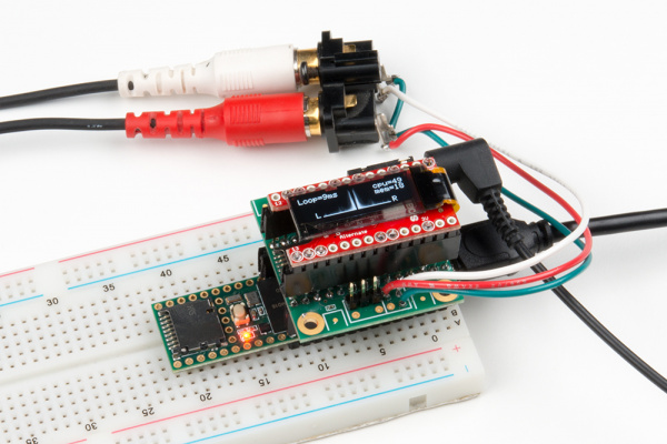
Example: Audio Board-Compatible Connection
This example shows off using the TeensyView with the audio platform. It takes incoming audio data on both line-in channels and displays a 40-bin FFT for each, plus some CPU usage info.
Hardware Requirements
- Teensy 3.1 to 3.6 (Note: CPU usage at 100% on the 3.1 with both FFTs enabled)
- TeensyView set to alternate jumpers
- Audio board with a line-in connection added
- Optional: Headphones attached to headphone out port (passes audio)
Choose the example TeensyViewAudio from the menu, compile and run. You should see all sorts of graphic demos go by on the screen. (Note: These can progress at different speeds depending on which Teensy is used.)
Alternately, copy the code from here:
language:c
/******************************************************************************
  TeensyViewAudio.ino
  Example using the TeensyView with the Teensy Audio board

  Marshall Taylor @ SparkFun Electronics, December 6, 2016
  https://github.com/sparkfun/SparkFun_TeensyView_Arduino_Library

  This is modified FFT example software.  It passes L/R audio channels to the
  headphone output while displaying the FFTs as a bar graph on the OLED, with
  CPU usage reports.

  Compatible with:
  Teensy 3.1 + Teensy Audio Board (100% processor usage)
  Teensy 3.2 + Teensy Audio Board (100% processor usage)
  Teensy 3.5 + Teensy Audio Board
  Teensy 3.6 + Teensy Audio Board

  Resources:
  Requires the Teensy Audio library

  Development environment specifics:
  Arduino IDE 1.6.12 w/ Teensyduino 1.31
  Arduino IDE 1.8.1 w/ Teensyduino 1.35
  TeensyView v1.0

  This code is released under the [MIT License](http://opensource.org/licenses/MIT).

  Please review the LICENSE.md file included with this example. If you have any questions
  or concerns with licensing, please contact techsupport@sparkfun.com.

  Distributed as-is; no warranty is given.
******************************************************************************/
#include <Audio.h>
#include <Wire.h>
#include <SPI.h>
#include <SD.h>
#include <SerialFlash.h>

// GUItool: begin automatically generated code
AudioInputI2S            audioInput;     //xy=458,218
AudioAnalyzeFFT1024      LeftFFT;          //xy=672,138
AudioAnalyzeFFT1024      RightFFT;      //xy=683,295
AudioOutputI2S           audioOutput;    //xy=686,219
AudioConnection          patchCord1(audioInput, 0, LeftFFT, 0);
AudioConnection          patchCord2(audioInput, 0, audioOutput, 0);
AudioConnection          patchCord3(audioInput, 1, audioOutput, 1);
AudioConnection          patchCord4(audioInput, 1, RightFFT, 0);
AudioControlSGTL5000     audioShield;    //xy=467,310
// GUItool: end automatically generated code

const int myInput = AUDIO_INPUT_LINEIN;
//const int myInput = AUDIO_INPUT_MIC;

#include <TeensyView.h>  // Include the TeensyView library

///////////////////////////////////
// TeensyView Object Declaration //
///////////////////////////////////
//Standard
//#define PIN_RESET 15
//#define PIN_DC    5
//#define PIN_CS    10
//#define PIN_SCK   13
//#define PIN_MOSI  11

//Alternate (Audio)
#define PIN_RESET 2
#define PIN_DC    21
#define PIN_CS    20
#define PIN_SCK   14
#define PIN_MOSI  7

TeensyView oled(PIN_RESET, PIN_DC, PIN_CS, PIN_SCK, PIN_MOSI);

void setup()
{
  // Set up audio stuff:
  // Audio connections require memory to work.  For more
  // detailed information, see the MemoryAndCpuUsage example
  AudioMemory(20);

  // Enable the audio shield and set the output volume.
  audioShield.enable();
  audioShield.inputSelect(myInput);
  audioShield.volume(0.5); //Pass-through volume

  // Configure the window algorithm to use
  LeftFFT.windowFunction(AudioWindowHanning1024);
  RightFFT.windowFunction(AudioWindowHanning1024);

  //Initialize the OLED
  oled.begin();
  // clear(ALL) will clear out the OLED's graphic memory.
  // clear(PAGE) will clear the Arduino's display buffer.
  oled.clear(ALL);  // Clear the display's memory (gets rid of artifacts)
  // To actually draw anything on the display, you must call the
  // display() function.
  oled.display();
  // Give the splash screen some time to shine
  delay(2000);
}

unsigned long last_time = millis();
uint8_t overlayCounter = 0;
float lastLoopTime = 0;
uint16_t lastCPU = 0;
uint16_t lastMem = 0;

float leftBands[40] = {
  0, 0, 0, 0, 0, 0, 0, 0, 0, 0,
  0, 0, 0, 0, 0, 0, 0, 0, 0, 0,
  0, 0, 0, 0, 0, 0, 0, 0, 0, 0,
  0, 0, 0, 0, 0, 0, 0, 0, 0, 0
};

float RightBands[40] = {
  0, 0, 0, 0, 0, 0, 0, 0, 0, 0,
  0, 0, 0, 0, 0, 0, 0, 0, 0, 0,
  0, 0, 0, 0, 0, 0, 0, 0, 0, 0,
  0, 0, 0, 0, 0, 0, 0, 0, 0, 0
};

void loop()
{
  float loopTime;
  int i;

  //calc loopTime
  unsigned long this_time = millis();
  if (this_time > last_time)
  {
    loopTime = (this_time - last_time);
  }
  last_time = this_time;

  //Update data every 20 frames for readability
  overlayCounter++;
  if (overlayCounter > 20)
  {
    lastLoopTime = loopTime;
    lastCPU = AudioProcessorUsageMax();
    AudioProcessorUsageMaxReset();
    lastMem = AudioMemoryUsageMax();
    AudioMemoryUsageMaxReset();

    overlayCounter = 0;
  }

  //Draw a frame
  oled.clear(PAGE);

  //Draw left bands
  for (i = 0; i < 40; i++)
  {
    if (leftBands[i] > 0.5) leftBands[i] = 0.25;
    oled.line(62 - i, 31, 62 - i, 31 - (leftBands[i] * 127));
  }

  //Draw Right bands
  for (i = 0; i < 40; i++)
  {
    if (RightBands[i] > 0.5) RightBands[i] = 0.25;
    oled.line(65 + i, 31, 65 + i, 31 - (RightBands[i] * 127));
  }

  //Overlay info
  //  loop time
  oled.setCursor(0, 0);
  oled.print("Loop=");
  oled.print((uint8_t)lastLoopTime);
  oled.print("ms");
  //  Teensy Audio info
  oled.setCursor(83, 0);
  oled.print("cpu=");
  oled.print(lastCPU);
  oled.setCursor(91, 8);
  oled.print("mem=");
  oled.print(lastMem);
  //  L/R letters
  oled.setCursor(15, 24);
  oled.print("L");
  oled.setCursor(108, 24);
  oled.print("R");

  if (LeftFFT.available()) {
    // each time new FFT data is available
    for (i = 0; i < 40; i++) {
      leftBands[i] = LeftFFT.read(i);
    }
  }
  if (RightFFT.available()) {
    // each time new FFT data is available
    for (i = 0; i < 40; i++) {
      RightBands[i] = RightFFT.read(i);
    }
  }

  oled.display();

}
The important lesson from this sketch is that the constructor is passed the alternate set of pins, and can be used concurrently with the Audio board.
Use the same command from the ScreenDemo and paint the screen with whatever you need to display!
Example: Prop Shield-Compatible Connection
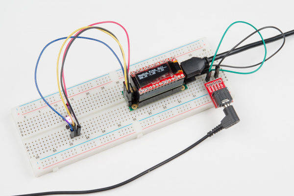
This example shows off using the TeensyView with the Prop Shield. This is a demonstration and test of all features on the Prop Shield and won't work on the LC prop shield, which doesn't have motion sensors.
The example:
- Creates a test file on the Flash (you may lose existing data) that contains RGB data
- Initializes the IMUs
- Initializes the Audio platform
- Displays heading, pitch and roll on the screen
- Generates a sine wave of pitch and filter based on physical orientation --- kind of like a Theremin!
- Continuously reads flash data from the test file and applies it to the APA102 LED
Wire the LED and speaker to the Prop Shield using the connection table:
| Prop Shield |
Function |
|---|---|
| G | APA102 Ground (Pin 3) |
| C | APA102 Clock In (Pin 2) |
| D | APA102 Data In (Pin 1) |
| 5 | APA102 VCC (Pin 4) |
| - | Headphone ring |
| + | Headphone tip |
Hardware Requirements
- Teensy 3.1 to 3.6
- TeensyView set to the following:
- RST set to default
- DC set to alternate
- CS set to alternate
- CLK set to default
- mosi set to default
- Prop Shield with:
- (optional) 1 AP102 attached to LED port -- 1m APA102 Strip or 5m APA102 Strip shown
- (optional) Speaker attached to speaker port -- Audio Jack and Audio Jack Breakout shown
Choose the example TeensyViewProp from the menu, compile and run. After the splash screen, the sketch will start, and the display will switch to orientation information. (Note: With so many included libraries, this can take awhile to compile!)
Alternately, copy the code from here:
language:c
/******************************************************************************
  TeensyViewProp.ino
  Example using the TeensyView with the Teensy Prop Shield.

  Marshall Taylor @ SparkFun Electronics, December 6, 2016
  https://github.com/sparkfun/SparkFun_TeensyView_Arduino_Library

  This enables all resources on the Teensy Prop Shield and operates them with
  the TeensyView.

  Accelerometer data is used to drive Teensy Audio system (bends pitch)
  Flash is programmed with LED data at boot (note: comment out flash erasor if necessary)
  LED continuously reads flash file for color information (Driven raw by SPI)
  TeensyView continuously updated with pitch, roll, and heading information.

  Compatible with:
  Teensy 3.1 + Prop Shield
  Teensy 3.2 + Prop Shield
  Teensy 3.5 + Prop Shield
  Teensy 3.6 + Prop Shield

  Resources:
  Requires the Teensy Audio library
  NXPMotionSense Library
  EEPROM Library
  SerialFlash Library


  Development environment specifics:
  Arduino IDE 1.6.12
  TeensyView v1.0

  This code is released under the [MIT License](http://opensource.org/licenses/MIT).

  Please review the LICENSE.md file included with this example. If you have any questions
  or concerns with licensing, please contact techsupport@sparkfun.com.

  Distributed as-is; no warranty is given.
******************************************************************************/


//********************IMU test*******************//
#include <NXPMotionSense.h>
#include <Wire.h>
#include <EEPROM.h>
NXPMotionSense imu;
NXPSensorFusion filter;
//********************IMU test*******************//

//********************Audio test*******************//
#include <Audio.h>
#include <Wire.h>
#include <SPI.h>
#include <SD.h>
#include <SerialFlash.h>
// GUItool: begin automatically generated code
AudioSynthWaveformSine   sine4;          //xy=321,367
AudioSynthWaveformSine   sine3;          //xy=323,314
AudioSynthWaveformSine   sine2;          //xy=324,264
AudioSynthWaveformSine   sine1;          //xy=325,213
AudioMixer4              mixer1;         //xy=506,303
AudioSynthWaveformDc     dc1;            //xy=517,382
AudioFilterStateVariable filter1;        //xy=695,311
AudioFilterStateVariable filter2;        //xy=851,342
AudioOutputAnalog        dac1;           //xy=1028,366
AudioConnection          patchCord1(sine4, 0, mixer1, 3);
AudioConnection          patchCord2(sine3, 0, mixer1, 2);
AudioConnection          patchCord3(sine2, 0, mixer1, 1);
AudioConnection          patchCord4(sine1, 0, mixer1, 0);
AudioConnection          patchCord5(mixer1, 0, filter1, 0);
AudioConnection          patchCord6(dc1, 0, filter1, 1);
AudioConnection          patchCord7(dc1, 0, filter2, 1);
AudioConnection          patchCord8(filter1, 0, filter2, 0);
AudioConnection          patchCord9(filter2, 0, dac1, 0);
// GUItool: end automatically generated code
//********************Audio test*******************//

//********************Flash Test*******************//
//#include <SerialFlash.h>
//#include <SPI.h>
const int FlashChipSelect = 6; // digital pin for flash chip CS pin
SerialFlashFile file; //Working file
uint16_t fileIndex = 0;
//********************Flash Test*******************//

//********************TeensyView*******************//
#include <TeensyView.h>  // Include the SFE_TeensyView library

///////////////////////////////////
// TeensyView Object Declaration //
///////////////////////////////////
//Standard
#define PIN_RESET 15
//#define PIN_DC    5
//#define PIN_CS    10
#define PIN_SCK   13
#define PIN_MOSI  11

//Alternate (Audio)
//#define PIN_RESET 2
#define PIN_DC    21
#define PIN_CS    20
//#define PIN_SCK   14
//#define PIN_MOSI  7

TeensyView oled(PIN_RESET, PIN_DC, PIN_CS, PIN_SCK, PIN_MOSI);
//********************TeensyView*******************//

void setup()
{
  // These three lines of code are all you need to initialize the
  // OLED and print the splash screen.
  Serial.begin(115200);
  // Before you can start using the OLED, call begin() to init
  // all of the pins and configure the OLED.
  oled.begin();
  // clear(ALL) will clear out the OLED's graphic memory.
  // clear(PAGE) will clear the Arduino's display buffer.
  oled.clear(ALL);  // Clear the display's memory (gets rid of artifacts)
  // To actually draw anything on the display, you must call the
  // display() function.
  oled.display();

  delay(2000);
  oled.clear(PAGE);
  oled.setCursor(0, 0);
  oled.print("Heading");
  oled.setCursor(50, 0);
  oled.print("Pitch");
  oled.setCursor(90, 0);
  oled.print("Roll");
  oled.line(0, 9, 127, 9);
  oled.display();

  //********************Audio test*******************//
  AudioMemory(40);
  mixer1.gain(0, 0.1);
  mixer1.gain(1, 0.1);
  mixer1.gain(2, 0.1);
  mixer1.gain(3, 0.1);
  filter1.frequency(500);
  filter1.octaveControl(2);
  filter1.resonance(2);
  filter2.frequency(500);
  filter1.octaveControl(2);
  filter2.resonance(2);
  dc1.amplitude(0);
  setSines(110);
  pinMode(5, OUTPUT);
  digitalWrite(5, HIGH); // turn on the amplifier
  delay(10);
  //********************Audio test*******************//

  Serial.begin(9600);

  //********************IMU test*******************//
  imu.begin();
  filter.begin(100);
  //********************IMU test*******************//

  //********************RAW APA102*******************//
  pinMode(7, OUTPUT); //Configure chip select pin
  //********************RAW APA102*******************//

  //********************Flash Test*******************//
  if (!SerialFlash.begin(FlashChipSelect)) {
    Serial.println("Unable to access SPI Flash chip");
  }
  uint8_t id[5];
  SerialFlash.readID(id);
  Serial.println("ID word:");
  Serial.print("0x");
  Serial.println(id[0], HEX);
  Serial.print("0x");
  Serial.println(id[1], HEX);
  Serial.print("0x");
  Serial.println(id[2], HEX);
  Serial.print("0x");
  Serial.println(id[3], HEX);
  //clearFlash();  //Use this to erase all... this holds the program in a while loop when done.
  prepareTestFile();  //This creates a test file IF it doesn't exist
  listTestFile();
  //********************Flash Test*******************//

}
//********************RAW APA102*******************//
void setLED( uint8_t r, uint8_t g, uint8_t b )
{
  uint8_t brightness = 0b00001000; //Quarter bright
  SPI.beginTransaction(SPISettings(4000000, MSBFIRST, SPI_MODE0));
  digitalWrite(7, HIGH);  // enable access to LEDs
  SPI.transfer(0);
  SPI.transfer(0);
  SPI.transfer(0);
  SPI.transfer(0);
  SPI.transfer(0b11100000 | brightness);
  SPI.transfer(b);
  SPI.transfer(g);
  SPI.transfer(r);
  digitalWrite(7, LOW);  // enable access to LEDs
  SPI.endTransaction();
  //This sends data to the LED
}
//********************RAW APA102*******************//

//********************Flash Test*******************//
//Test data for mem R/W (also LED display data, as r1, g1, b1, r2, g2, b2...)
uint8_t const colorwheel[128 * 3] = {
  64, 22, 10, 63, 21, 11, 63, 19, 12, 63, 18, 14, 63, 16, 15, 63, 15, 16, 62, 14, 18, 62, 12, 19,
  61, 11, 21, 60, 10, 22, 60, 9, 24, 59, 8, 25, 58, 7, 27, 57, 6, 28, 56, 5, 30, 55, 4, 32,
  54, 3, 33, 53, 3, 35, 52, 2, 36, 51, 1, 38, 49, 1, 39, 48, 0, 41, 47, 0, 42, 45, 0, 44,
  44, 0, 45, 42, 0, 47, 41, 0, 48, 39, 0, 49, 38, 0, 51, 36, 0, 52, 35, 0, 53, 33, 0, 54,
  32, 1, 55, 30, 1, 56, 28, 2, 57, 27, 3, 58, 25, 3, 59, 24, 4, 60, 22, 5, 60, 21, 6, 61,
  19, 7, 62, 18, 8, 62, 16, 9, 63, 15, 10, 63, 14, 11, 63, 12, 12, 63, 11, 14, 63, 10, 15, 64,
  9, 16, 63, 8, 18, 63, 7, 19, 63, 6, 21, 63, 5, 22, 63, 4, 24, 62, 3, 25, 62, 3, 27, 61,
  2, 28, 60, 1, 30, 60, 1, 32, 59, 0, 33, 58, 0, 35, 57, 0, 36, 56, 0, 38, 55, 0, 39, 54,
  0, 41, 53, 0, 42, 52, 0, 44, 51, 0, 45, 49, 0, 47, 48, 0, 48, 47, 1, 49, 45, 1, 51, 44,
  2, 52, 42, 3, 53, 41, 3, 54, 39, 4, 55, 38, 5, 56, 36, 6, 57, 35, 7, 58, 33, 8, 59, 32,
  9, 60, 30, 10, 60, 28, 11, 61, 27, 12, 62, 25, 14, 62, 24, 15, 63, 22, 16, 63, 21, 18, 63, 19,
  19, 63, 18, 21, 63, 16, 22, 64, 15, 24, 63, 14, 25, 63, 12, 27, 63, 11, 28, 63, 10, 30, 63, 9,
  32, 62, 8, 33, 62, 7, 35, 61, 6, 36, 60, 5, 38, 60, 4, 39, 59, 3, 41, 58, 3, 42, 57, 2,
  44, 56, 1, 45, 55, 1, 47, 54, 0, 48, 53, 0, 49, 52, 0, 51, 51, 0, 52, 49, 0, 53, 48, 0,
  54, 47, 0, 55, 45, 0, 56, 44, 0, 57, 42, 0, 58, 41, 0, 59, 39, 1, 60, 38, 1, 60, 36, 2,
  61, 35, 3, 62, 33, 3, 62, 32, 4, 63, 30, 5, 63, 28, 6, 63, 27, 7, 63, 25, 8, 63, 24, 9
};
void clearFlash( void )
{
  Serial.print("Erasing flash");
  SerialFlash.eraseAll();
  while (SerialFlash.ready() == false)
  {
    // wait, 30 seconds to 2 minutes for most chips
    Serial.print(".");
    delay(100);
  }
  Serial.println("Done!");
  Serial.println("Program held.  Now comment out clearFlash(); and recompile");
  while (1);
}

void prepareTestFile( void )
{
  //Check if file exists, if not, create it.
  if (SerialFlash.exists("testfile.dat") == 0)
  {
    //File doesn't exist
    if (SerialFlash.create("testfile.dat", 128 * 3) == true)
    {
      Serial.println("Created testfile.dat");
    }
    else
    {
      Serial.println("File creation failed!!!");
    }
  }
  if (SerialFlash.exists("testfile.dat"))
  {
    Serial.println("File Exists, trying to open...");
    file = SerialFlash.open("testfile.dat");
    if (file)
    { // true if the file exists
      Serial.println("testfile.dat opened");
      uint8_t buffer[3];
      for (int i = 0; i < (128 * 3); i = i + 3)
      {
        buffer[0] = colorwheel[i];
        buffer[1] = colorwheel[i + 1];
        buffer[2] = colorwheel[i + 2];
        file.seek(i);
        file.write(buffer, 3);
        Serial.print(".");
      }
      file.close();
      Serial.println("Test data generation complete");
    }
    else
    {
      Serial.println("testfile.dat not opened!!!");
    }
  }
}

void listTestFile( void )
{
  file = SerialFlash.open("testfile.dat");
  if (file)
  { // true if the file exists
    Serial.println("testfile.dat opened");
    uint8_t buffer[3];
    fileIndex = 0;
    for (int i = 0; i < 128; i++)
    {
      file.seek(fileIndex);
      fileIndex = fileIndex + 3;
      file.read(buffer, 3);
      Serial.println(buffer[0], HEX);
      Serial.println(buffer[1], HEX);
      Serial.println(buffer[2], HEX);
    }
    file.close();
  }
  else
  {
    Serial.println("testfile.dat not opened!!!");
  }
}
//********************Flash Test*******************//

//********************Audio test*******************//
void setSines(float root)
{
  sine1.frequency(root);
  sine1.amplitude(0.25);
  sine2.frequency(root * 2);
  sine2.amplitude(0.25);
  sine3.frequency(root * 3);
  sine3.amplitude(0.25);
  sine4.frequency(root * 4);
  sine4.amplitude(0.25);
}
//********************Audio test*******************//

void loop()
{
  //********************IMU test*******************//
  float ax, ay, az;
  float gx, gy, gz;
  float mx, my, mz;
  float roll, pitch, heading;
  if (imu.available())
  {
    // Read the motion sensors
    imu.readMotionSensor(ax, ay, az, gx, gy, gz, mx, my, mz);
    // Update the SensorFusion filter
    filter.update(gx, gy, gz, ax, ay, az, mx, my, mz);
    // print the heading, pitch and roll
    roll = filter.getRoll();
    pitch = filter.getPitch();
    heading = filter.getYaw();
    Serial.print("Orientation: ");
    Serial.print(heading);
    Serial.print(" ");
    Serial.print(pitch);
    Serial.print(" ");
    Serial.println(roll);

    //********************Audio test*******************//
    dc1.amplitude(pitch / 20);
    setSines(55 + (roll * 10));
    //********************Audio test*******************//

    //********************TeensyView*******************//
    oled.setCursor(0, 13);
    oled.print("                     ");
    oled.setCursor(0, 13);
    oled.print(heading);
    oled.setCursor(43, 13);
    oled.print(pitch);
    oled.setCursor(83, 13);
    oled.print(roll);
    oled.display();
    //********************TeensyView*******************//
  }
  //********************IMU test*******************//

  //********************Flash Test*******************//
  if (fileIndex >= (128 * 3)) fileIndex = 0;
  fileIndex = fileIndex + 3;
  if (!SerialFlash.begin(FlashChipSelect)) {
    Serial.println("Unable to access SPI Flash chip");
  }
  file = SerialFlash.open("testfile.dat");
  if (file)
  { // true if the file exists
    uint8_t buffer[3];
    file.seek(fileIndex);
    file.read(buffer, 3);
    file.close();
    //Serial.println(buffer[0], HEX); //Show red channel to serial console
    //********************RAW APA102*******************//
    setLED( buffer[0], buffer[1], buffer[2] );
    //********************RAW APA102*******************//
  }
  //********************Flash Test*******************//
}
After compiling and uploading, the TeensyView will display heading, pitch and roll, while the LED proves flash communication and the speaker proves that the audio system is functioning.
Resources and Going Further
The TeensyView was designed to be as flexible as possible while still being able to nest down into a low-profile addition to the Teensy.
The TeensyView works with some really heavy examples, but they're really only demonstrations. What to do with it is up to you! They're great for adding simple debug info to a mobile project, while a diligent pixel artist could implement a whole menu system.
More information about the SSD1306 controller and the TeensyView design can be found here:
- Product GitHub Repository
- Library GitHub Repository
- Drawing Bitmaps --- How to make a bitmap array
- OLED Memory Map --- Talks about screen geometry and making fonts
Additional projects and sketches that use the TeensyView:
- The HighSpeedTest, in the examples folder, draws alternating pixels as fast as possible. This can be used to experiment with the limits of the TeensyView's OLED.
For additional inspiration, check out these other tutorials based on displays:
