MiniGen Hookup Guide
 SFUptownMaker
Introduction
The MiniGen was designed to be used either as a stand-alone board or as a shield that can be placed on top of an Arduino Pro Mini. It's capable of generating sine, square, or triangle waves at up to 3MHz, and approximately 1Vp-p. The output is at a DC offset of Vcc/2. Neither the offset nor the amplitude can be varied.
By default, the MiniGen ships configured with a 3.3V regulator enabled, and thus, should only be used with 3.3V signals(or 3.3V Pro Minis, as linked above). There's a jumper on the back that can be soldered over to bypass the regulator for 5V use; just be careful not to power the board with more than 5V if you bypass the regulator!
For more information about the MiniGen, please see the GitHub repository, where you'll find a library, example code, and design files.
Suggested Reading
Before using the MiniGen, here are a few tutorials you should be familiar with:
- AC vs DC
- Analog vs Digital signals
- The SPI interface
- Some soldering is required, so you may want to brush up on those skills.
- What is a Shield?
- Using an Arduino Library - You'll want the MiniGen Library installed, so if you're unsure how to do that, check out this tutorial.
Connections
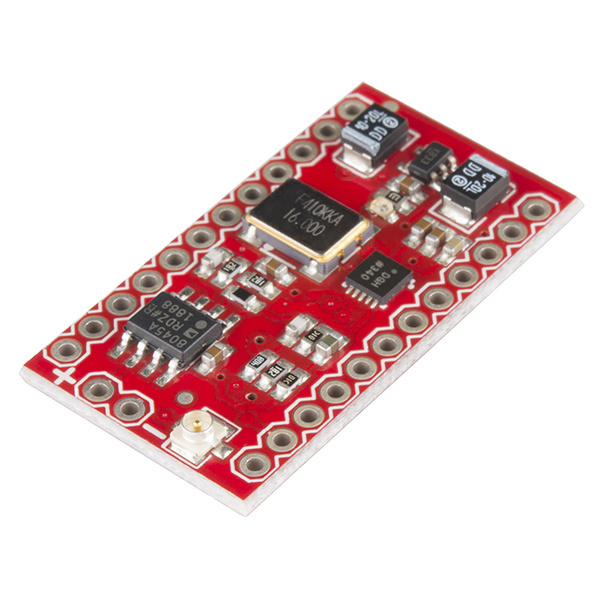
Top
Here's the top of the board. Due to the tight layout and lack of space on this shield, the labels had to live on the bottom side of the PCB.

There are two output sources: a 2x1 0.1" spaced header and a u.FL connector. The u.FL connector is shield as ground.
The output end of the board should be at the opposite end from the FTDI connector when installed on a Pro Mini.
Bottom
Take a look at the picture above. Let's go through the labeled connections one at a time.
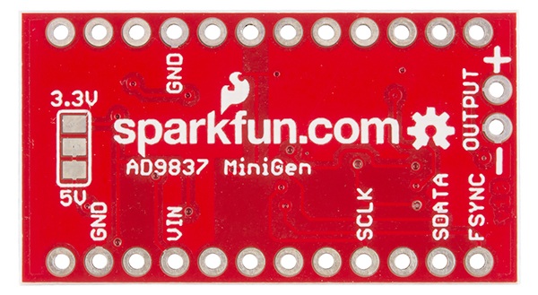
- GND - Only one of these needs to be connected at a time; that means you can get away with headers on one side only.
VIN - By default, this goes to a 3.3V regulator. If you want to use the board with a 5V Pro Mini, you should put a blob of solder on the jumper pads on the back to connect all three together.
Danger! Adding a solder jumper will bypass the 3.3V voltage regulator, you will be powering the board at 5V. While most of the components on the board can handle 5V, the 16MHz crystal oscillator is not. It can only handle 3.3V. You would need to find a way to cut the trace connecting to the 16MHz and 3.3V voltage regulator in order to reroute 3.3V to the 16MHz crystal oscillator's circuit.- OUTPUT+ - This is the anti-aliased output from the AD9837. Expect to see a 1Vp-p signal, offset from ground by 1/2 Vin.
- OUTPUT- - Connected to ground.
- SCLK - SPI clock input. The SPI bus can handle up to 40MHz input.
- SDATA - Input from the master device. Note that register contents cannot be read out from the AD9837 part; it lacks a DOUT pin.
- FSYNC - Equivalent to chip select.
SPI interface
As mentioned above, the SPI interface can be driven at up to 40MHz. The SPI interface should be at or close to the supply voltage for the chip (3.3V by default).
If you elect to write your own SPI control for this, the clock idles low (CPOL = 0), and data is latched on the rising edge (CPHA = 1). This corresponds to SPI Mode 2.
Assembly
The MiniGen works as both a normal breakout board and as an add-on to the Arduino Pro Mini boards. Note that the SparkFun Pro Micro, Arduino Nano, and other similar form-factor boards won't work, as they don't have the necessary SPI pins in the same location.
Output connection
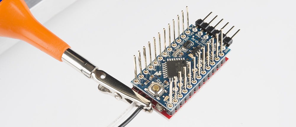
Before you go any further, think about what you're going to do with the output of the MiniGen. Do you want bare wires (as I've done, here) on the output pads? Are you going to use the u.FL connector? .1" header pins? Make that decision now, and put your desired connector on the board.
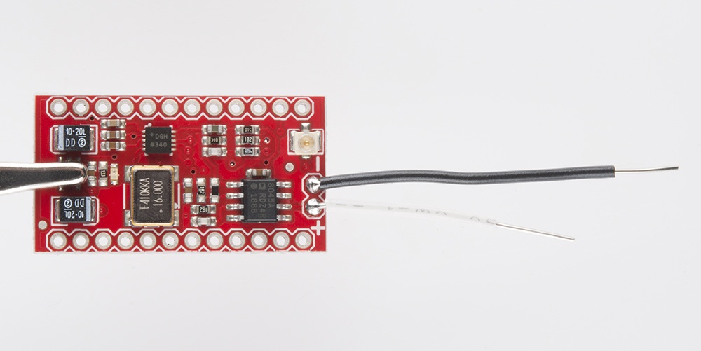
I've elected to put two solid-core wires on this board, so I can plug the ends into a breadboard or clip a scope probe onto them. I left the lengths uneven to avoid having them touch and short.
Adding headers
We'll start by explaining how to put male pin headers on the MiniGen. This will let us plug it into a breadboard easily, or into female headers soldered onto an Arduino Pro Mini (which we'll go over later).
Start by trimming the pin headers to the right length. You'll need 12 pins per side.
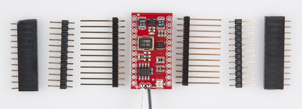
You can, of course, use any style of header you want: on display here are our female headers, our short male headers, and our long male headers. I'll show you some options with each of these.
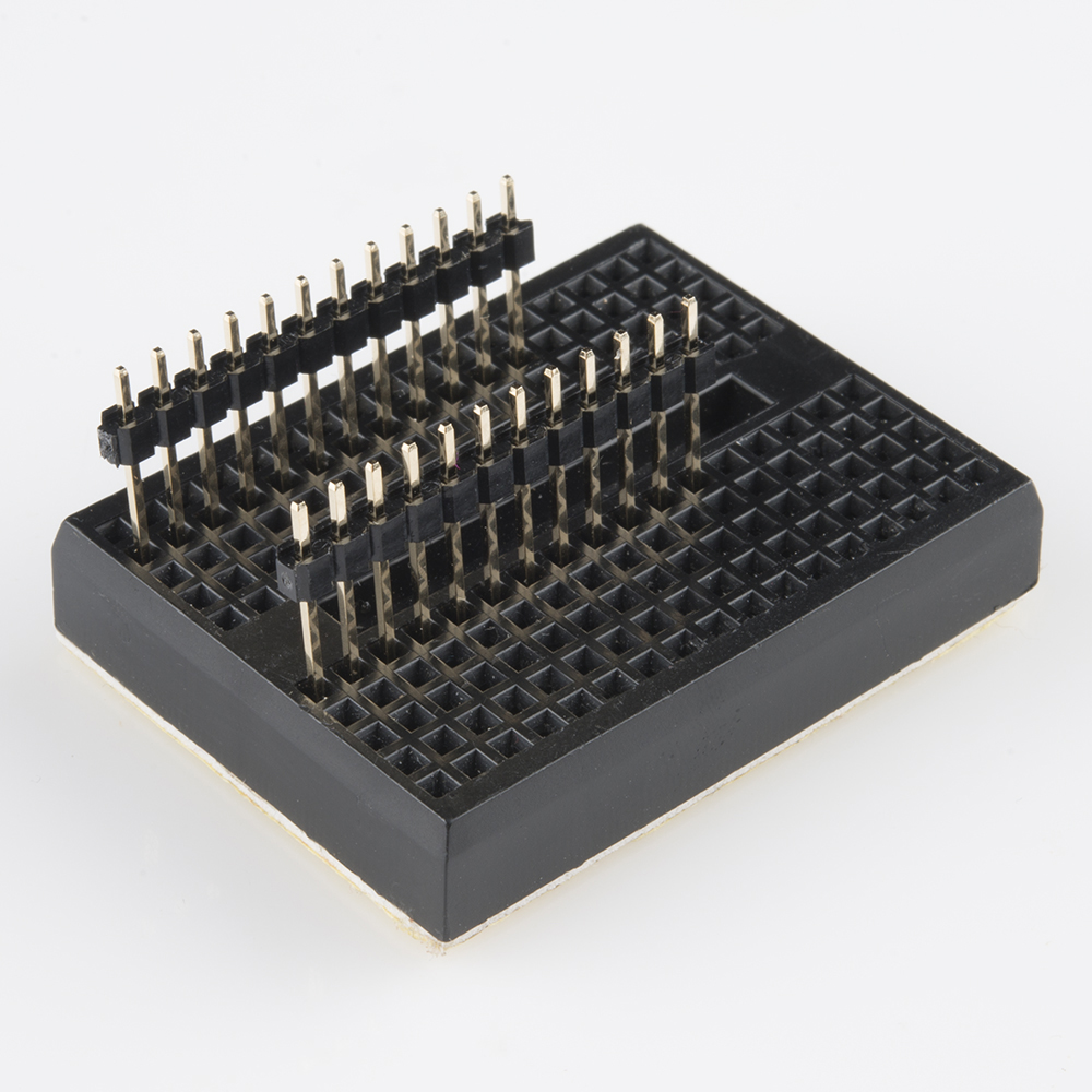
The easiest way to ensure that the pins are nicely perpendicular to your board (and thus, will mate easily with another board or breadboard) is to insert them into a breadboard. The width of the MiniGen is such that one row of pins inserted right next to the center line will place the other row of pins one column off the edge on the other side, as pictured below.
Once the pin headers are in place, you can lower the MiniGen board onto them. The board can be soldered on component side up or component side down; depending on what you plan to do with it, one of those is likely to be better.
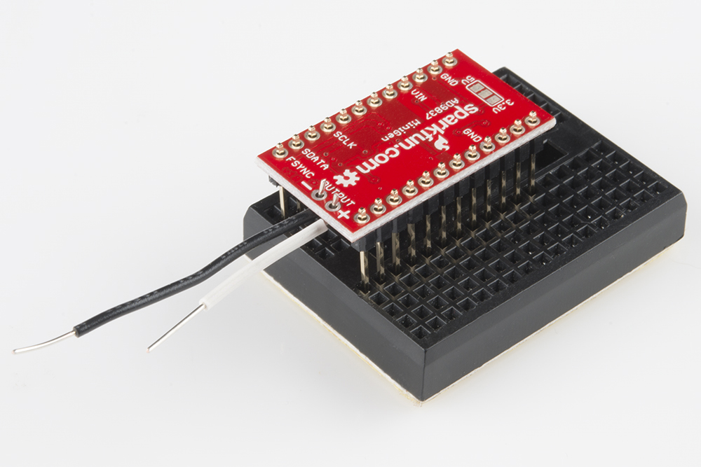
If you put the board on the headers component side down, as shown below, you can see the pin labels. That makes this method better for use as a breakout board; however, you'll be unable to put the board on the top side of a Pro Mini. We'll talk about that in a minute.
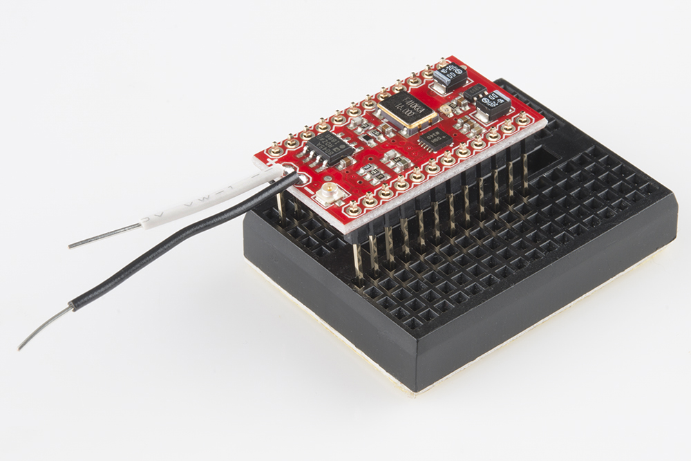
Flipping the board over, component side up, will allow you to mount it on a Pro Mini board that has female headers on its top side. I'll show you both of these cases fully assembled, so you can see the implications of each.
If you plan to put female headers on your Pro Mini, I strongly suggest that you solder down the male headers on the MiniGen, then use those to hold the female headers at an auspicious angle on the Pro Mini. That way, they'll mate smoothly in the future.
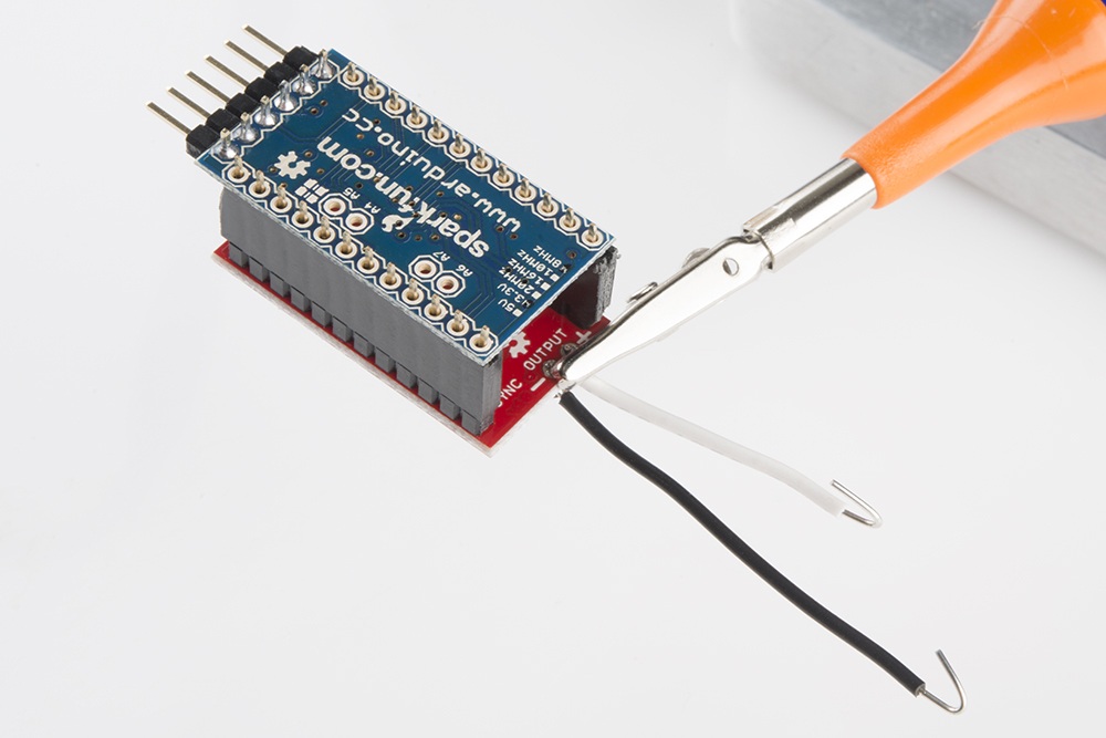
You can see a couple of points: the pin headers on the MiniGen have been soldered in with the long pins on the opposite side from the components, and the receptacles are on the component side of the Pro Mini.
As I mentioned above, if you elected to put your headers in with the components "down", you can't put the MiniGen on top of your Pro Mini. However, if you use our long breakaway male headers, you can put the pins in from the bottom, and they'll protrude on top enough for you to stack another board on top, such as the MiniFet Shield or a Pro Mini Protoshield. This has the disadvantage of covering up the u.FL connector on top of the board, but that may not be a problem for you.
If you use this method, be certain there's a gap between the bottom of the Pro Mini and the components on the top of the MiniGen.
Arduino Library
The MiniGen has a fairly comprehensive Arduino Library to help users write Arduino code easily.
Accessing the Library
The library can be downloaded as part of the Github repository for the MiniGen board. Simply download the zip file of the entire repository, then copy the "libraries" directory from the "Arduino" folder in the unzipped repository into your Arduino Sketchbook directory. The location of your Sketchbook can be found in the "Preferences" window of the Arduino IDE. If you have trouble installing the library, please consult our tutorial.
Using the Library
To use the library, add the following two lines to the top of your sketch:
language:c
#include <MiniGen.h>
#include <SPI.h>
Note that both lines must be present; failure to include the SPI library will cause code compilation to fail.
Once you've included the library, you must instantiate a MiniGen object in your sketch, like this:
language:c
MiniGen sig_gen;
You can replace the name sig_gen with any name you like; our example sketches will use that name, however.
If you're using the board with something other than an Arduino Pro Mini, you can change the chip select pin (referred to in the library and datasheet as the FSYNC pin) used by the code by calling the constructor like this, instead:
language:c
sig_gen = MiniGen(pin_number);
Change pin_number to the desired pin on the Arduino; note, however, that the SPI functionality of the Atmega requires that pin 10 be an output, so you'll lose the ability to do other things with that pin.
Library Commands
Once you've created your MiniGen object, there are several commands that you can send to the MiniGen board to operate it.
language:c
sig_gen.reset();
This command will reset the MiniGen to its default behavior: it clears the phase offset registers, resets the frequency to 100Hz, and disables the output, resulting in a DC voltage at approximately 1/2 the supply voltage on the output.
language:c
sig_gen.setMode(newMode);
The newMode parameter can be one of the following values: MiniGen::TRIANGLE, MiniGen::SINE, MiniGen::SQUARE, or MiniGen::SQUARE_2. The frequency of the output will depend on the value in the selected frequency register; more on that below. For the first three options, the frequency will be at the set frequency; for the fourth, it will be one-half the set frequency.
language:c
sig_gen.selectFreqReg(reg);
The AD9837 chip has two registers that store possible output frequencies. These can be selected by passing the parameters MiniGen::FREQ0 and MiniGen::FREQ1 to this function. This allows the user to adjust the frequency by swapping registers rather than writing to the active register; since a full adjust of the frequency requires two SPI writes, this allows the change to take effect at once with no intermediate frequency step.
The FREQ registers are divided into a low word and a high word, each of which is 14-bits long; the output frequency is equal to the low word times 0.0596Hz plus the high word times 976.5Hz. The total output frequency is equal to the sum of the two registers.
language:c
uint32_t freqRegVal = sig_gen.freqCalc(desiredFrequency);
This helper function returns a 32-bit value (an unsigned long Arduino data type, or uint32_t in more general terms), which, when written to the AD9837 frequency register, will result in an output at desiredFrequency. The value passed to the function should be a floating point number, in Hz. When this 32-bit value is written to the FREQ registers, the result will be (approximately) desiredFrequency.
To write the value to the FREQ registers, there are several functions of interest. The reason for this is simple: speed. Writing the frequency value to the AD9837 can take anywhere from one to three SPI transactions; using the appropriate function allows the user to save execution time where possible.
language:c
sig_gen.adjustFreq(reg, mode, newFreq);
This method takes the longest. reg can be either MiniGen::FREQ0 or MiniGen::FREQ1, depending on where the user wants to write the value. mode can be either MiniGen::FULL, MiniGen::COARSE, or MiniGen::FINE. For the first, newFreq should be an 32-bit unsigned value (as returned by freqCalc(), or calculated by the user elsewhere); in that case, the frequency setting operation will require three SPI transactions. For the second and third, 'newFreq' should be a 16-bit unsigned value, and the operation will require two SPI transactions.
When the mode parameter is MiniGen::FULL, the value of the output will be equal to the passed parameter times 0.0596 Hz. When mode is MiniGen::COARSE, you will be writing to the high word of the register, and each count will increase the frequency by 976.5Hz. When mode is MiniGen::FINE, you'll be writing to the low word, and each count will increase the frequency of the output by .0596Hz. Splitting the writes into coarse and fine allows the user to minimize the number of writes required to change the frequency.
language:c
sig_gen.FreqAdjustMode(newMode);
sig_gen.adjustFreq(reg, newFreq);
If speed is important, you can pre-select the mode. This reduces the write time to two SPI writes for FULL and one for COARSE or FINE. Note that this requires care on the part of the user to pass the appropriate value to adjustFreq(); if the mode is set to FULL and a 32-bit value isn't passed, or to COARSE or FINE and a 16-bit value isn't passed, the result will not be as desired.
language:c
sig_gen.selectPhaseReg(reg);
sig_gen.adjustPhaseShift(reg, newPhase);
It's possible to adjust the phase shift between the input clock and the output signal. As is the case with setting the frequency, there are two phase shift registers. They can be selected by passing MiniGen::PHASE0 or MiniGen::PHASE1 as the reg parameter in the above functions.
For the newPhase parameter, the value should be a 16-bit unsigned value. Only 12 bits of that value are used, so it should be a maximum of 4095. Each count represents .00153 radians (.551 degrees). However, since the phase is measured relative to the input frequency, this setting is of limited value.
Resources and Going Further
Here are some useful resources to look at for the MiniGen board:
- MiniGen product page - Product page on SparkFun.
- AD9837 product page at Analog Devices's website - Lots of good info here about the product, other related products, and direct digital synthesis in general.
- AD8045 product page - Information about the op-amp on the board.
- Analog Devices's FilterWizard - A nice online tool that will help you tweak the values in this circuit, if you decide you need a different filter design.
- GitHub repository - Contains board design files and the Arduino Library.
The MiniGen can be used for all kinds of signal synthesis, but one of the more intriguing possibilities it opens up is signal transmission by Frequency Shift Keying. By switching between the FREQ0 and FREQ1 registers, it's possible to encode data on the output.
If you make anything neat using FSK with the MiniGen, or any other projects, let us know!
For more SparkFun tutorial fun, check out these other offerings: