XBee Shield Hookup Guide
 jimblom
 Introduction
The XBee Shield gives your Arduino a seamless interface to XBee -- one of the most popular wireless platforms around. With XBee, instead of being tied down by a serial cable -- inches away from a paired device -- your Arduino can pass data over the air to another device hundreds of feet away.
Part of what makes XBee so popular is its simplicity. XBees are controlled over a serial UART interface -- in the most basic operation they can be used as a wireless serial cable. Setting up XBee networks and addresses is also simplified with Digi's free software -- XCTU -- which we explain in a separate tutorial.
Covered In This Tutorial
The goal of this tutorial is to set up wireless XBee communication between a computer and an Arduino/XBee Shield combo. Then, using a terminal program, we can remotely send data to an Arduino, or read data off of it.

We'll begin by examining the schematics and hardware of the XBee Shield, then move on to example code. First we'll set up a test program to make sure our XBees are communicating with each other. Then we'll move on to the remote control Arduino sketch.
Required Materials
To follow along with this tutorial, you will need the following materials. You may not need everything though depending on what you have. Add it to your cart, read through the guide, and adjust the cart as necessary.
- 1x XBee Shield -- The star of this tutorial.
- You'll also need headers to install into your shield. We recommend stackable headers.
- 1x Arduino -- The XBee Shield should work with any Arduino-compatible board -- Uno, RedBoard, Mega, you name it.
2x XBees -- XBees exist in a variety of series, frequencies, and ranges. If you're just getting started with XBee, we highly recommend going with Series 1 models -- either with a trace antenna, wire antenna or u.fl connector.
- For more help picking an XBee, check out our XBee Buying Guide.
Heads up! While this tutorial was written for XBee Series 1, you can still follow along using XBee Series 3 modules. Just make sure to configure it with the 802.15.4 (Series 1) firmware. For more information, check out the Exploring XBees and XCTU tutorial.- 1x Explorer -- The Explorer board allows you to connect an XBee to your computer. You can use either the Explorer USB, Explorer USB Dongle, or Explorer Serial.
- Depending on which explorer you have, you may also need a matching mini-B USB or serial cables.
- At least one computer with X-CTU installed.
- The latest version of X-CTU is available for both Mac and Windows!
Tools
You will need a soldering iron, solder, and general soldering accessories.


Weller WLC100 Soldering Station
TOL-14228Suggested Reading
Before reading through this tutorial, we highly recommend checking out the Exploring XBees and XCTU tutorial.
Exploring XBees and XCTU
That tutorial will introduce you to XCTU and explain how to configure XBee networks and addresses. In addition to that tutorial, we also recommend checking these guides out:
- Serial Communication -- Serial communication is critical to controlling and managing XBees.
- Arduino Shields -- The basics of Arduino Shields, including how to assemble a shield.
- XBee Buying Guide -- We highly recommend Series 1 XBee's, if this is your first time playing with them. If you're curious about other XBee classes, check out this guide!
How to Solder: Through-Hole Soldering
Serial Communication
Arduino Shields v2
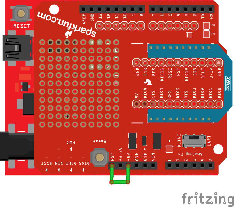
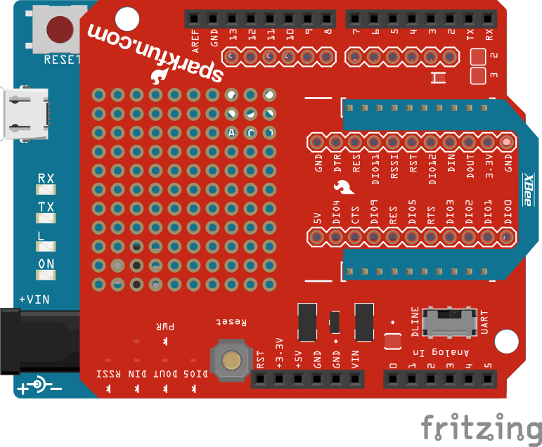
Hardware Overview
Here's a quick overview of the most components of the XBee Shield:
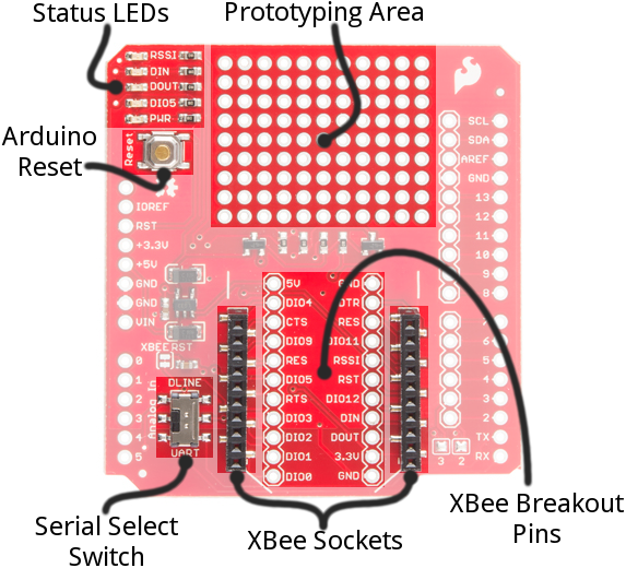
Below we'll go more in-depth on the most important components of the shield.
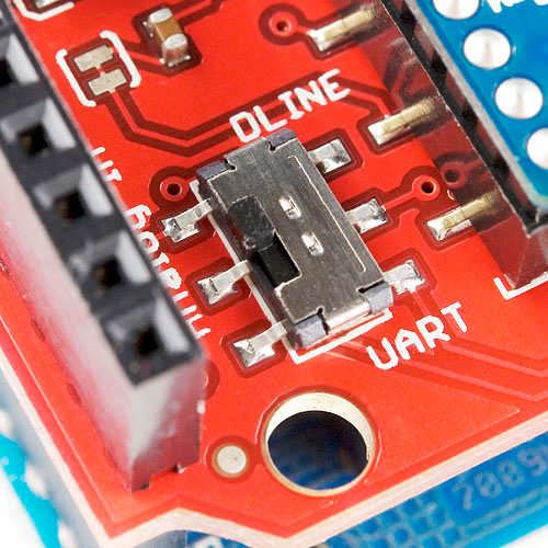
UART/Software Serial Switch
One of the most important components on the XBee Shield is the DLINE/UART switch. This switch controls which Arduino pins interface with the XBee.
The Arduino Uno has a single hardware UART, which is usually either used for programming (via the Arduino's serial bootloader) or communication with the serial monitor. That serial port can only be used to communicate with one device at any time, lest you run into problems of bus contention. There's also a chance that, during program upload, spurious -- even harmful -- data might be sent to any device attached to the Arduino's hardware UART.
So to avoid any problems that might arise from connecting the XBee to the Arduino's hardware UART, we usually take advantage of the Software Serial library, connecting the XBee's RX and TX pins to a pair of free digital pins on the Arduino.
To select between software and hardware serial, the XBee Shield includes a small, surface-mount slide switch. This switch allows you to select between the hardware serial port (UART position) and a software serial port connected to pins 2 (Arduino-side RX) and 3 (Arduino-side TX).
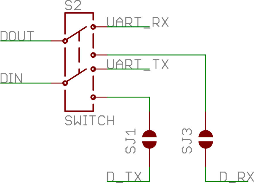
For all of our example sketches we'll assume the switch is in the DLINE position. At the very least, make sure the switch is in the "DLINE" position when uploading sketches.
Status LED Indicators
There are 5 LEDs on the XBee Shield. Each of these LEDs connects to a pin on the XBee, which does most of the LED driving. Here's a table explaining the operation of each LED:
| LED Label | LED Color | XBee Pin Connection | Default Operation Notes |
|---|---|---|---|
| PWR | Red | 3.3V | Indicates power is present. |
| DIO5 | Green | Associate/DIO5 | Associated indicator -- blinks when the XBee is associated with another XBee. |
| DOUT | Red | DOUT | Indicates wireless data is being received. |
| DIN | Green | DIN | Indicates wireless data is being transmitted. |
| RSSI | Green | PWM0/RSSI | Indicates relative signal strength (RSSI) of last received transmission. |
These LEDs can be very useful for debugging. The DIO5/Associate indicator should blink when the XBee is paired with a compatible device. The RSSI LED is actually PWM'd so it will be brighter when the paired XBee is closer (sending a stronger signal).
Assembly Tips
Before you can use the XBee Shield with your Arduino, you'll need to solder in some headers.
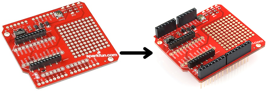
Check out the assembly page of our Shield tutorial for all of the tips and tricks related to header installation.
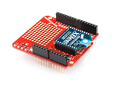
XBee Socket
There is some white silkscreen on the Shield PCB to help orient your XBee as you're plugging it in. Make sure to match up the XBee's two diagonal edges with the two diagonal lines on the PCB.
With everything installed, you're ready for the next step! Time to code...
Example: Communication Test
Double-Check Your XBee Network
Before continuing with this example, you'll need to make sure your XBee's are configured correctly -- they need to be on the same network and have compatible destination and MY addresses. By default, XBees will all be compatibly configured, but we recommend setting up unique network ID's and addresses. Check out the Configuring Networks page of our Exploring XBee's and XCTU tutorial for help with that.
Exploring XBees and XCTU
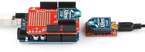
This example assumes you have XCTU installed and two compatibly-configured XBees -- one connected to your computer via a USB Explorer (or Dongle, or Serial Explorer) and another plugged into the Shield/Arduino.
The Arduino Sketch
Let's start simple. In this section, we'll upload a sketch which passes data between your serial monitor and the XBe using the serial UART. This sketch can be use to create a "portal of communication" between your Arduino's serial monitor, and another XBee (connected to a computer via a USB Explorer). The first uses software serial defined pins on an Arduino. The second example uses the native hardware serial defined pins.
Software Serial Passthrough
Here's the sketch we'll use. It makes use of the SoftwareSerial library, which is included with all of the recent Arduino releases. Before uploading this sketch, make sure the switch on the Shield is in the "DLINE" position!
Copy and upload the sketch below.
language:c
/*****************************************************************
XBee_Serial_Passthrough.ino

Set up a software serial port to pass data between an XBee Shield
and the serial monitor.

Hardware Hookup:
  The XBee Shield makes all of the connections you'll need
  between Arduino and XBee. If you have the shield make
  sure the SWITCH IS IN THE "DLINE" POSITION. That will connect
  the XBee's DOUT and DIN pins to Arduino pins 2 and 3.

*****************************************************************/
// We'll use SoftwareSerial to communicate with the XBee:
#include <SoftwareSerial.h>

//For Atmega328P's
// XBee's DOUT (TX) is connected to pin 2 (Arduino's Software RX)
// XBee's DIN (RX) is connected to pin 3 (Arduino's Software TX)
SoftwareSerial XBee(2, 3); // RX, TX

//For Atmega2560, ATmega32U4, etc.
// XBee's DOUT (TX) is connected to pin 10 (Arduino's Software RX)
// XBee's DIN (RX) is connected to pin 11 (Arduino's Software TX)
//SoftwareSerial XBee(10, 11); // RX, TX

void setup()
{
  // Set up both ports at 9600 baud. This value is most important
  // for the XBee. Make sure the baud rate matches the config
  // setting of your XBee.
  XBee.begin(9600);
  Serial.begin(9600);
}

void loop()
{
  if (Serial.available())
  { // If data comes in from serial monitor, send it out to XBee
    XBee.write(Serial.read());
  }
  if (XBee.available())
  { // If data comes in from XBee, send it out to serial monitor
    Serial.write(XBee.read());
  }
}
Software Serial Note
The demo code was originally designed for the ATmega328P on the Arduino Uno. Not all the pins can support change interrupts for a serial Rx pin depending on what Arduino microcontroller is used. If you were using it with ATmega2560 (i.e. Arduino Mega 2560) or ATmega32U4 (i.e. Arduino Leonardo, Pro Micro 5V/16MHz, Pro Micro 3.3V/8Mhz, FioV3, etc.), you would need to re-define the software serial pin definitions, remove the solder jumpers for pin 3 & 2, and reroute the pins. For more information about the limitations, try looking at the Arduino reference language for the Software Serial library.Pin Definitions
To use re-define the software serial pins on an Arduino Mega 2560 or Arduino Leonardo, you would just need to comment out the line where it says: SoftwareSerial XBee(2, 3); // RX, TX
//SoftwareSerial XBee(10, 11); // RX, TXReroute Pins
To reroute the pins, on an Arduino Mega 2560 or Leonardo, you would need to remove the solder jumper and reroute pads to the respective pins. |
 |
| Pins Rerouted for ATmega2560-Based Arduino | Pins Rerouted for ATmega32U4-Based Arduino |
Basically when the XCTU or serial terminal opens a COM port to the Arduino, computer resets the microcontroller while looking for the XBee. Therefore, it can’t communicate with the XBee because the Arduino is rebooting.
Hardware Serial Passthrough
This example is for those trying to use the hardware UART on an ATmega32U4-based Arduino. Copy and upload the sketch below. You can also download it here.
language:c
/*****************************************************************
Leonardo_XBee_Serial_Passthrough.ino

Set up a serial port to pass data between an XBee Shield
and the serial monitor.

Hardware Hookup:
  The XBee Shield makes all of the connections you'll need
  between Arduino and XBee. If you have the shield make
  sure the SWITCH IS IN THE "UART" POSITION. That will connect
  the XBee's DOUT and DIN pins to Arduino pins 0 and 1.
*****************************************************************/

// Leonardo Serial  is the USB port
// Leonardo Serial1 is pins 0 and 1

void setup()
{
  // Set up both ports at 9600 baud. This value is most important
  // for the XBee. Make sure the baud rate matches the config
  // setting of your XBee.
  Serial1.begin(9600);  //XBee/UART1/pins 0 and 1
  Serial.begin(9600);   //USB

}

void loop()
{
  if (Serial.available()) //USB
  { // If data comes in from serial monitor, send it out to XBee
  Serial1.write(Serial.read()); //XBee/UART1/pins 0 and 1

  }
  if (Serial1.available())   //XBee/UART1/pins 0 and 1
  { // If data comes in from XBee, send it out to serial monitor
    Serial.write(Serial1.read());  //Serial port

  }
}
What You Should See
After you've uploaded the code, follow this series of steps to verify that everything is working:
- Open the Arduino's Serial Monitor. Make sure the baud rate is set to 9600.
- Switch to XCTU and click over to console mode.
- Type something in the console view, it should show up on the Serial Monitor.
- Type something into the Serial Monitor (and press "Send"), it should show up in the console view.
- Yay!
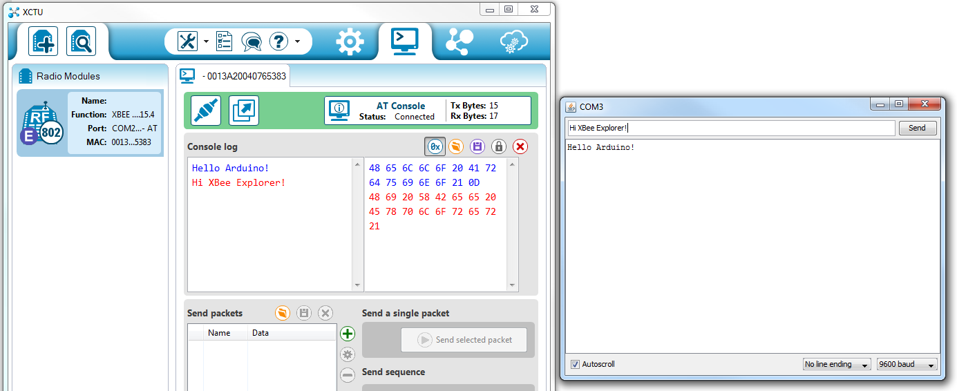
You can use this setup to create a chat system. If you have another computer nearby, try to see how far your XBees can be from each other while still reliably communicating.
If your XBee's aren't communicating with each other, try getting them closer together (if they were far apart to begin with). Otherwise, check out our troubleshooting section of the Exploring XBee tutorial.
Example: Remote Control Arduino
Setting up a chat system is fun, but where XBees and the XBee Shield really shine is in passing data to and from an Arduino, so you can remotely control it or receive data from it. In this example, we'll create a simple serial interface, which can be used to set and read analog and digital pins.
Example Sketch
Here's the sketch. Copy and paste from below, or click here to download it.
language:c
/*****************************************************************
XBee_Remote_Control.ino
Write your Arduino's pins (analog or digital) or read from those
pins (analog or digital) using a remote XBee.
Jim Lindblom @ SparkFun Electronics
Original Creation Date: May 7, 2014

This sketch requires an XBee, XBee Shield and another XBee tied to
your computer (via a USB Explorer). You can use XCTU's console, or
another serial terminal program (even the serial monitor!), to send
commands to the Arduino.

Example usage (send these commands from your computer terminal):
    w#nnn - analog WRITE pin # to nnn
      e.g. w6088 - write pin 6 to 88
    d#v   - digital WRITE pin # to v
      e.g. ddh - Write pin 13 High
    r#    - digital READ digital pin #
      e.g. r3 - Digital read pin 3
    a#    - analog READ analog pin #
      e.g. a0 - Read analog pin 0

    - Use hex values for pins 10-13
    - Upper or lowercase works
    - Use 0, l, or L to write LOW
    - Use 1, h, or H to write HIGH

Hardware Hookup:
  The Arduino shield makes all of the connections you'll need
  between Arduino and XBee. Make sure the SWITCH IS IN THE
  "DLINE" POSITION.

Development environment specifics:
    IDE: Arduino 1.0.5
    Hardware Platform: SparkFun RedBoard
    XBee Shield & XBee Series 1 1mW (w/ whip antenna)
        XBee USB Explorer connected to computer with another
          XBee Series 1 1mW connected to that.

This code is beerware; if you see me (or any other SparkFun
employee) at the local, and you've found our code helpful, please
buy us a round!

Distributed as-is; no warranty is given.
*****************************************************************/
// SoftwareSerial is used to communicate with the XBee
#include <SoftwareSerial.h>

SoftwareSerial XBee(2, 3); // Arduino RX, TX (XBee Dout, Din)

void setup()
{
  // Initialize XBee Software Serial port. Make sure the baud
  // rate matches your XBee setting (9600 is default).
  XBee.begin(9600);
  printMenu(); // Print a helpful menu:

}

void loop()
{
  // In loop() we continously check to see if a command has been
  //  received.
  if (XBee.available())
  {
    char c = XBee.read();
    switch (c)
    {
    case 'w':      // If received 'w'
    case 'W':      // or 'W'
      writeAPin(); // Write analog pin
      break;
    case 'd':      // If received 'd'
    case 'D':      // or 'D'
      writeDPin(); // Write digital pin
      break;
    case 'r':      // If received 'r'
    case 'R':      // or 'R'
      readDPin();  // Read digital pin
      break;
    case 'a':      // If received 'a'
    case 'A':      // or 'A'
      readAPin();  // Read analog pin
      break;
    }
  }
}

// Write Digital Pin
// Send a 'd' or 'D' to enter.
// Then send a pin #
//   Use numbers for 0-9, and hex (a, b, c, or d) for 10-13
// Then send a value for high or low
//   Use h, H, or 1 for HIGH. Use l, L, or 0 for LOW
void writeDPin()
{
  while (XBee.available() < 2)
    ; // Wait for pin and value to become available
  char pin = XBee.read();
  char hl = ASCIItoHL(XBee.read());

  // Print a message to let the control know of our intentions:
  XBee.print("Setting pin ");
  XBee.print(pin);
  XBee.print(" to ");
  XBee.println(hl ? "HIGH" : "LOW");

  pin = ASCIItoInt(pin); // Convert ASCCI to a 0-13 value
  pinMode(pin, OUTPUT); // Set pin as an OUTPUT
  digitalWrite(pin, hl); // Write pin accordingly
}

// Write Analog Pin
// Send 'w' or 'W' to enter
// Then send a pin #
//   Use numbers for 0-9, and hex (a, b, c, or d) for 10-13
//   (it's not smart enough (but it could be) to error on
//    a non-analog output pin)
// Then send a 3-digit analog value.
//   Must send all 3 digits, so use leading zeros if necessary.
void writeAPin()
{
  while (XBee.available() < 4)
    ; // Wait for pin and three value numbers to be received
  char pin = XBee.read(); // Read in the pin number
  int value = ASCIItoInt(XBee.read()) * 100; // Convert next three
  value += ASCIItoInt(XBee.read()) * 10;     // chars to a 3-digit
  value += ASCIItoInt(XBee.read());          // number.
  value = constrain(value, 0, 255); // Constrain that number.

  // Print a message to let the control know of our intentions:
  XBee.print("Setting pin ");
  XBee.print(pin);
  XBee.print(" to ");
  XBee.println(value);

  pin = ASCIItoInt(pin); // Convert ASCCI to a 0-13 value
  pinMode(pin, OUTPUT); // Set pin as an OUTPUT
  analogWrite(pin, value); // Write pin accordingly
}

// Read Digital Pin
// Send 'r' or 'R' to enter
// Then send a digital pin # to be read
// The Arduino will print the digital reading of the pin to XBee.
void readDPin()
{
  while (XBee.available() < 1)
    ; // Wait for pin # to be available.
  char pin = XBee.read(); // Read in the pin value

  // Print beggining of message
  XBee.print("Pin ");
  XBee.print(pin);

  pin = ASCIItoInt(pin); // Convert pin to 0-13 value
  pinMode(pin, INPUT); // Set as input
  // Print the rest of the message:
  XBee.print(" = ");
  XBee.println(digitalRead(pin));
}

// Read Analog Pin
// Send 'a' or 'A' to enter
// Then send an analog pin # to be read.
// The Arduino will print the analog reading of the pin to XBee.
void readAPin()
{
  while (XBee.available() < 1)
    ; // Wait for pin # to be available
  char pin = XBee.read(); // read in the pin value

  // Print beginning of message
  XBee.print("Pin A");
  XBee.print(pin);

  pin = ASCIItoInt(pin); // Convert pin to 0-6 value
  // Printthe rest of the message:
  XBee.print(" = ");
  XBee.println(analogRead(pin));
}

// ASCIItoHL
// Helper function to turn an ASCII value into either HIGH or LOW
int ASCIItoHL(char c)
{
  // If received 0, byte value 0, L, or l: return LOW
  // If received 1, byte value 1, H, or h: return HIGH
  if ((c == '0') || (c == 0) || (c == 'L') || (c == 'l'))
    return LOW;
  else if ((c == '1') || (c == 1) || (c == 'H') || (c == 'h'))
    return HIGH;
  else
    return -1;
}

// ASCIItoInt
// Helper function to turn an ASCII hex value into a 0-15 byte val
int ASCIItoInt(char c)
{
  if ((c >= '0') && (c <= '9'))
    return c - 0x30; // Minus 0x30
  else if ((c >= 'A') && (c <= 'F'))
    return c - 0x37; // Minus 0x41 plus 0x0A
  else if ((c >= 'a') && (c <= 'f'))
    return c - 0x57; // Minus 0x61 plus 0x0A
  else
    return -1;
}

// printMenu
// A big ol' string of Serial prints that print a usage menu over
// to the other XBee.
void printMenu()
{
  // Everything is "F()"'d -- which stores the strings in flash.
  // That'll free up SRAM for more importanat stuff.
  XBee.println();
  XBee.println(F("Arduino XBee Remote Control!"));
  XBee.println(F("============================"));
  XBee.println(F("Usage: "));
  XBee.println(F("w#nnn - analog WRITE pin # to nnn"));
  XBee.println(F("  e.g. w6088 - write pin 6 to 88"));
  XBee.println(F("d#v   - digital WRITE pin # to v"));
  XBee.println(F("  e.g. ddh - Write pin 13 High"));
  XBee.println(F("r#    - digital READ digital pin #"));
  XBee.println(F("  e.g. r3 - Digital read pin 3"));
  XBee.println(F("a#    - analog READ analog pin #"));
  XBee.println(F("  e.g. a0 - Read analog pin 0"));
  XBee.println();
  XBee.println(F("- Use hex values for pins 10-13"));
  XBee.println(F("- Upper or lowercase works"));
  XBee.println(F("- Use 0, l, or L to write LOW"));
  XBee.println(F("- Use 1, h, or H to write HIGH"));
  XBee.println(F("============================"));
  XBee.println();
}
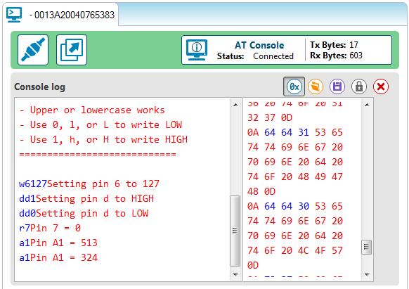
Upload that, then switch over to your XCTU console window. You'll use the XBee connected to your computer to control and read data from your Arduino.
All of the XBee magic occurs in serial prints and reads. To send data from the Arduino XBee, XBee.print() and XBee.println()'s are used to write strings and other data. To read data from the computer XBee, we can use XBee.read(), adding XBee.available() tests to check if data has come in. That's all there is to it!
Check out the comments in the code for a line-by-line dissection.
Remote Controlling/Receiving
When the Arduino sketch first starts up, it will print a helpful usage menu. After that's printed, follow the directions to send commands to your Arduino. To control pins 10, 11, 12, and 13, send the hexadecimal equivalent characters (A, B, C, and D).
w#nnn-- analog write pin#tonnn. Use leading zeros for single- and double-digit values.- Example:
w6088will write pin 6 to 88
- Example:
d#v-- digital write pin#tov.vcan be 1, h, or H for HIGH, and 0, l, or L for LOW.- Example:
ddhwill write pin 13 High
- Example:
r#- digital read digital pin#- Example:
r3will digtally read from pin 3.
- Example:
a#-- analog read analog pin#- Example:
a0will read analog pin 0
- Example:
In each case, the Arduino will respond with the action it's taken after you've sent a viable string.
As an initial test, try turning the D13 LED on and off, by sending dd1 and dd0.
Then try setting analog values, or reading from pins. Maybe try making it more advanced -- have a button press trigger an XBee communication. Or send an alert when an analog input rises past a certain threshold.
This example barely scrapes the surface of what the Arduino-XBee combination is capable of. XBee's allow you to remotely control your robot from the comfy confines of your computer. Or you can set up a network of XBees to monitor carbon-monoxide conditions in every room, while logging to a single computer.
The power of XBees comes from their simplicity -- they make your projects wireless by simply "serial printing".
Resources and Going Further
That should be enough to get you started. If you're looking for more XBee and XBee Shield info, check out these resources:
- Schematic -- If you confused about the layout of the schematic, check out this PDF.
- XBee Series 1 Manual -- For more advanced users, if you really want to take advantage of the XBee's unique abilities, check out this guide.
- XBee Wireless Class Materials -- Check out our teaching materials for the XBee class we lead every once-in-a-while.
- GitHub Repo -- This is where you'll find the latest PCB design files.
With XBee and the XBee Shield you have all of the tools necessary to take your project to the airwaves. What are you going to make? Need some inspiration? Check out these related tutorials:
- XBee WiFi Hookup Guide -- Take the next step with XBees, using the XBee WiFi. These modules allow you to connect to a wireless network and give your Arduino Internet access!
- Internet Datalogging with XBee WiFi -- Need to do a little "cloud"-based data logging. Check out this tutorial, which shows you how to stick sensor readings on the Internet using an XBee WiFi, XBee Shield, and Arduino?
- Simon Splosion Wireless -- This tutorial demonstrates one of many techniques to "hack" the Simon Says -- use XBee's to make the Simon game wireless!
- Getting Started With the RedBot -- The RedBot is our popular, Arduino-based robot platform. Once you get it rolling, you can take it a step further by controlling it with an XBee!
Simon Splosion Wireless
XBee WiFi Hookup Guide
Experiment Guide for RedBot with Shadow Chassis
Wireless Gesture Controlled Robot
Or check out this blog post for more ideas.