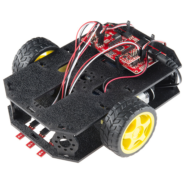
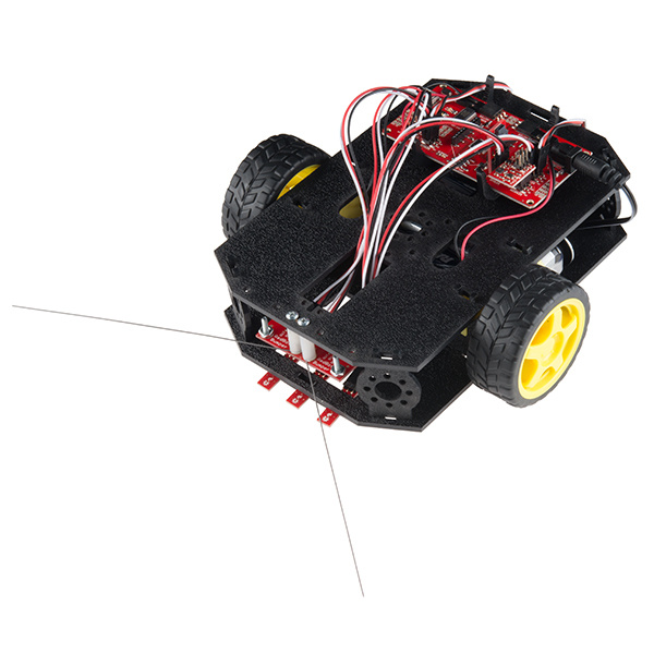
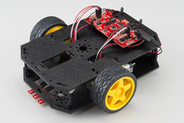
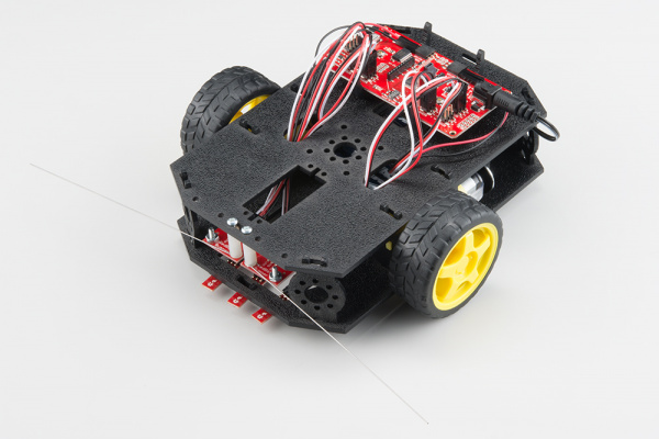
Experiment Guide for RedBot with Shadow Chassis
Introduction
The SparkFun RedBot is a great way to get your feet wet in the world of robotics. However, once you have assembled your RedBot, you may be at a loss as to where to go from there. This guide will go through nine different experiments, ranging from learning how to drive your RedBot to using an accelerometer to trigger your RedBot to move. Once you've mastered each experiment, you can take what you've learned in this guide and apply it to creating your own robot platform.
RedBot Basic Kit vs. SIK for RedBot
This tutorial will cover how to use everything in the SparkFun RedBot Basic Kit and the SparkFun Inventor's Kit for RedBot (SIK for RedBot).
SparkFun RedBot Basic Kit
ROB-13166SparkFun Inventor's Kit for RedBot
ROB-12649The SIK for RedBot contains a few extra parts in addition to the RedBot Kit that are covered in this tutorial. Sections pertaining to these extra parts will be marked with (SIK).
RedBot Basic Kit
If you have the RedBot Basic Kit, you can skip the steps marked with (SIK).
Alternatively, you can pick up additional sensors to install on your RedBot. These parts include the Wheel Encoder Kit, RedBot Buzzer, and two RedBot Mechanical Bumpers. Follow the sections in this guide that cover any of the extra sensors you might have.
SIK for RedBot
If you have the SIK for RedBot, you can follow all the sections in this guide, including those marked with (SIK).
Experiment List:
Here is a breakdown of each experiment presented in this tutorial. Click on the link to jump to that section, or continue reading to learn more about the hardware and library before starting on Experiment 1.
- Software Install and Basic Test
- Drive Forward
- Turning
- Push to Start & Making Sounds
- Bumpers
- Line Following with IR Sensors
- Encoder
- Accelerometer
- Remote Control
Extra Supplies Needed
- 4x AA batteries (if not using the SIK for RedBot)
- USB miniB cable
- Tape, paint, markers, pencils, etc for IR Sensors
Suggested Reading
If you still need to assemble your RedBot, visit our RedBot Assembly Guide for detailed instructions. Please note that are a couple of versions of the assembly guide. For an older version of the RedBot Kit, please see this assembly guide.
Assembly Guide for RedBot with Shadow Chassis
Already put together the RedBot? Great! It's a good idea to double-check the wiring. If you hooked up the RedBot differently, you can either change the example code to reflect your changes or rewire your bot as per the assembly guide.
Before you go any further, you should probably make certain that you're familiar with these other topics:
- What is an Arduino? - Since the RedBot is based off the Arduino platform, it's a good idea to understand what that means.
- Installing the Arduino IDE - If you don't have the Arduino software installed, this guide will help you out.
- Installing an Arduino Library - To get the most out of the RedBot, you'll want to install our RedBot library. This tutorial will show you how to install any library.
- Accelerometer basics - One of the core sensors for the RedBot is an accelerometer. To find out more about accelerometers, check out this guide.
- Analog to digital conversion - Many useful sensors for the RedBot will be analog. This guide will help you interface with them and make the most of the data you get back.
- Pulse width modulation (PWM) - The RedBot includes two headers with PWM signals, and uses PWM to control the speed of the motors. It's probably a good idea to be familiar with the concept.
- I2C - The RedBot Accelerometer, which ships with the RedBot kit, uses I2C to communicate with the RedBot. While the accelerometer is accessible through the library with no knowledge of I2C required, if you want to get more out of it, you can check out this tutorial.


