Experiment Guide for RedBot with Shadow Chassis
 bri_huang,
  Shawn Hymel,
  SFUptownMaker
Experiment 9: Remote Control
At the heart of almost every robotics project is remote control. Up to this point, we have only looked at autonomous or pre-programmed control of the RedBot. Using a few simple commands, we will setup the RedBot to respond to Serial data that is transmitted from your computer.
Let’s load this experiment onto the RedBot. Go to File > Examples > SparkFun RedBot Library > Exp9_SerialDrive or copy and paste the example code below:
language:c
/***********************************************************************
* Exp9_SerialDrive -- RedBot Experiment 9
*
* The first step to controlling the RedBot remotely is to first drive it
* from the Serial Monitor in a tethered setup.
*
* Hardware setup:
* After uploading this sketch, keep the RedBot tethered to your computer with
* the USB cable. Open up the Seral Monitor to send commands to the RedBot to
* drive.
*
* This sketch was written by SparkFun Electronics, with lots of help from
* the Arduino community. This code is completely free for any use.
*
* 15 Dec 2014 B. Huang
*
* This experiment was inspired by Paul Kassebaum at Mathworks, who made
* one of the very first non-SparkFun demo projects and brought it to the
* 2013 Open Hardware Summit in Boston. Thanks Paul!
***********************************************************************/
#include <RedBot.h>
RedBotMotors motors;
int leftPower; // variable for setting the drive power
int rightPower;
int data; // variable for holding incoming data from PC to Arduino
void setup(void)
{
Serial.begin(9600);
Serial.print("Enter in left and right motor power values and click [Send].");
Serial.print("Separate values with a space or non-numeric character.");
Serial.println();
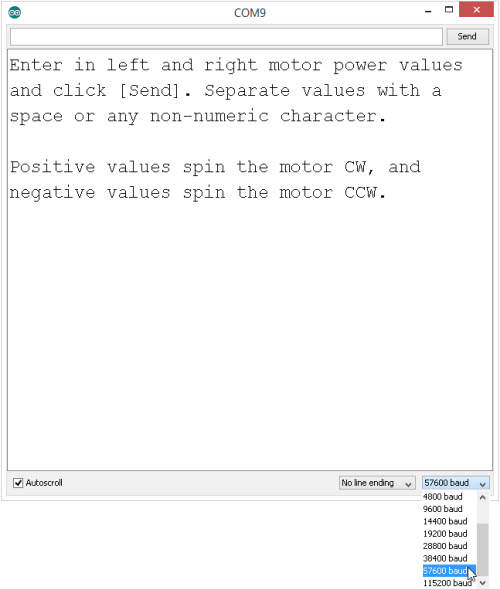
Serial.print("Positive values spin the motor CW, and negative values spin the motor CCW.");
}
void loop(void)
{
// if there is data coming in on the Serial monitor, do something with it.
if(Serial.available() > 0)
{
leftPower = Serial.parseInt(); // read in the next numeric value
leftPower = constrain(leftPower, -255, 255); // constrain the data to -255 to +255
rightPower = Serial.parseInt(); // read in the next numeric value
rightPower = constrain(rightPower, -255, 255); // constrain the data to -255 to +255
motors.leftMotor(leftPower);
motors.rightMotor(rightPower);
}
}
What You Should See
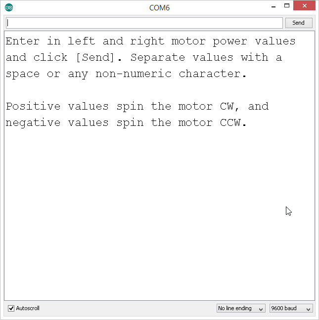
After uploading this sketch, open up the Serial Monitor.
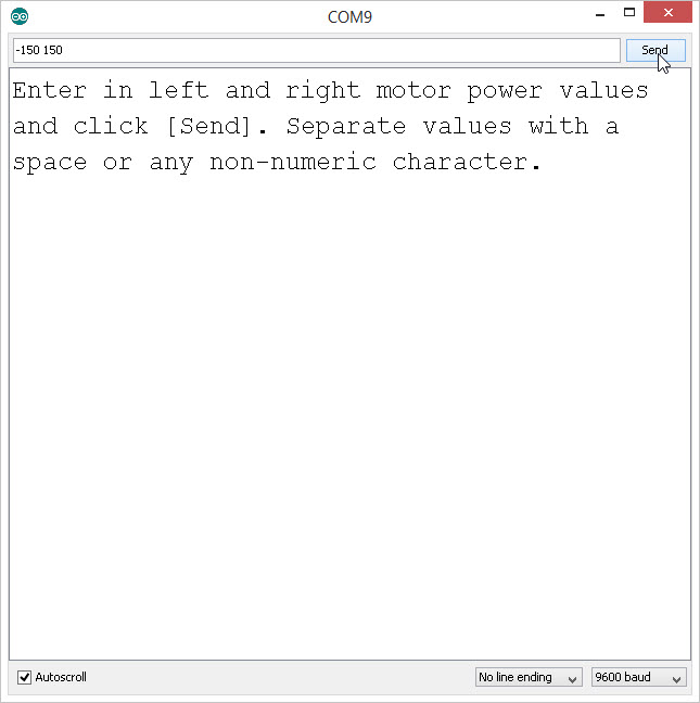
In the code, we print out a few lines in the setup() using the Serial.println() command. These are used as user-interface prompts. Type in one or two numbers into the input window and click [Send]. The motors should start spinning. The values that you send to the RedBot will drive the left and the right motors, respectively. What happens when you type in a negative value? How would you stop the motors?
Code to Note
language:c
Serial.begin(9600);
This first command in the setup() starts the Serial communication between the RedBot and your computer. The "9600" specifies the baud rate or speed that you can communicate. Did you notice that the RedBot response lagged a little from when you sent it commands to change speeds? Try changing the baud rate to 57600. Note that when you change the baud rate, you need to re-upload your code and change the speed on the Serial Monitor.
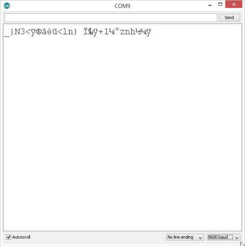
If you forget to change the baud rate in the Serial Monitor, all you'll see is gobbly-gook. Make sure the baud rate in the Serial Monitor matches what you have in your Serial.begin() in your code.
language:c
if(Serial.available() > 0)
{
}
In the loop() part of the code, we start with a simple if() conditional statement. Serial.available() returns the number of bytes waiting to be read in. Remember that this is on the RedBot. So, when we type in "-150 150" [Send], there are 8 characters worth of data being sent to the RedBot.
language:c
  leftPower = Serial.parseInt();  // read in the next numeric value
  leftPower = constrain(leftPower, -255, 255);  // constrain the data to -255 to +255

  rightPower = Serial.parseInt();   // read in the next numeric value
  rightPower = constrain(rightPower, -255, 255);  // constrain the data to -255 to +255
Next, we use a nifty function of the Serial object called .parseInt(). This function reads in the next numeric value and converts this to a number. Note that when we pass data back and forth on the Serial Monitor, we generally pass data as ASCII characters. Because these are not actually number values, we need to use this function to read in the data and convert them.
You can use this same method to send any number of data items. For this example, we're just sending two pieces of data (leftMotor power and rightMotor power). You can use this to signal turning on LEDs, making sounds, or moving motors.
Learn More: Serial
The Serial object in Arduino has many other methods, functions, and features. Serial communication is one of the simplest methods to send data, instructions, and commands between the RedBot and your computer. If you look closely at the RedBot, you should see two lights blinking back and forth whenever data is being sent or received.
One LED represents data being received (RX) and the other represents data being transmitted (TX). For the Arduino, all of this communication happens over two wires (one for RX and one for TX). We can send data at speeds up to 115200 baud (that's 115200 bytes per second!).
In today's world of GB/s data rates, this may not seem like that much, but this is remarkably fast given that it's just being sent over two very thin wires.
Going Further
Want to go wireless? Well -- you'll need a few things to get started. First, you'll need two XBee Series 1 and an XBee Explorer USB.
The XBee radio modules are ready to go with their default settings. The radios are on a generic network address (3332) and are broadcasting out to any and all radios that are on this network. Note: The default settings will not work in a classroom setting or where there may be more than one set of wireless RedBots.
To start, plug one XBee into the XBee Explorer USB. It is very important to make sure that the pins all line up and the XBee matches the white pentagonal outline on the XBee Explorer. Using a USB cable, connect this to your computer. Your computer may "find a new device" and attempt to install drivers. Allow your computer to complete this process before moving on.
Plug the other XBee into your RedBot. Again, make sure that the pins line up and the XBee matches the white pentagonal outline. Also, check to make sure that the switch next to the XBee header is set to XBEE HW SERIAL.
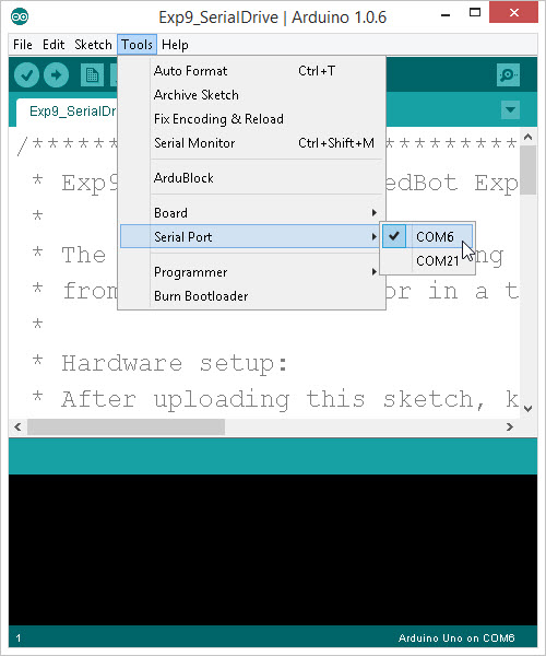
The RedBot should now be connected to your computer wirelessly: through the two XBees. The XBee Explorer will identify as a different Serial Port on your computer. Go to the Tools > Serial Port menu and change this to the Serial Port for the XBee.
Now, open up the Serial Monitor. Push the [Reset] button on the RedBot, and you should see text come across. Type in a couple numbers and see if your RedBot starts moving. With the default XBee configuration, you can only communicate at 9600 baud.
If you want to use a different baud rate, or you want to run multiple RedBots in a single classroom, you will need to re-configure each of the XBee radios. For this, you can use a program like XCTU. XCTU is a configuration tool made by Digi, the manufacturer of the XBee Wireless modules.
For more information on XBees or wireless projects check out our tutorial on Exploring XBees and XCTU to get started: