Experiment Guide for RedBot with Shadow Chassis
 bri_huang,
  Shawn Hymel,
  SFUptownMaker
Experiment 1: Software Install and Basic Test
Install Arduino IDE
In order to get your RedBot up and running, you'll first need to download the newest version of the Arduino software from www.arduino.cc. This software, known as the Arduino IDE (Integrated Development Environment), will allow you to program the board to do exactly what you want. It’s like a word processor for writing programs. Please visit our Installing Arduino IDE tutorial for step-by-step directions on installing the Arduino IDE.
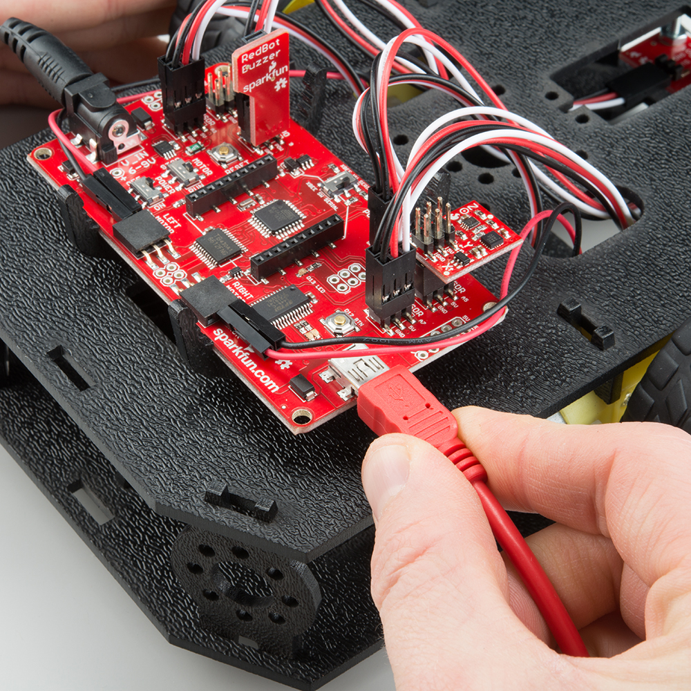
Connect your RedBot to your computer
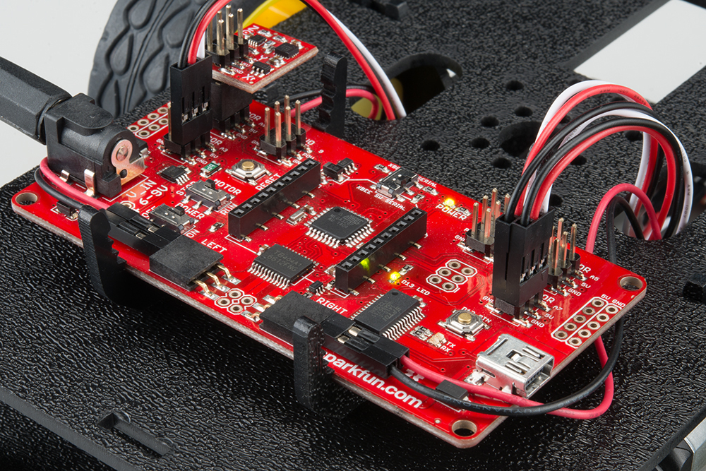
Use a USB miniB cable to connect the RedBot to one of your computer’s USB inputs. Make sure you have the four AA batteries in the battery holder.
Install FTDI drivers
Depending on your computer’s operating system, you will need to follow specific instructions. Please go to How to Install FTDI Drivers for specific instructions on how to install the FTDI drivers onto your RedBot.
Install the RedBot library
A library in Arduino is a set of files containing pre-written code that simplifies instructions and commands to perform certain tasks. We have written a specific library for the RedBot. Make sure you install the RedBot library. You will need it for all the example code. Click the button below to download it.
Unzip the downloaded file. Copy/Move the SparkFun RedBot Library folder to the libraries folder into your Arduino Documents folder. If you need a refresher on how to install an Arduino library, please see our library tutorial.
Example Code
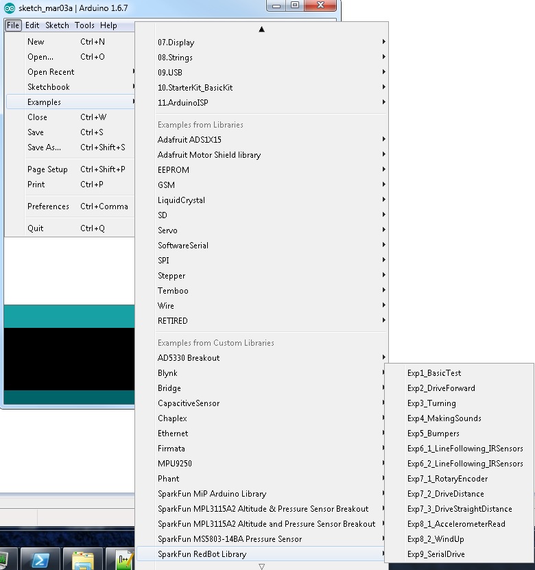
Included in the library are a set of examples for the 9 RedBot Experiments. Click on File > Examples > SparkFun RedBot Library, you should see a list of the 9 main Examples and 4 secondary examples we have created.
If you need to find the example code separately, click the button below
You can also find the RedBot Kit Experiments example code on the RedBot Github page. To download all the code, click the "Download ZIP" button on the right-hand side of the page.
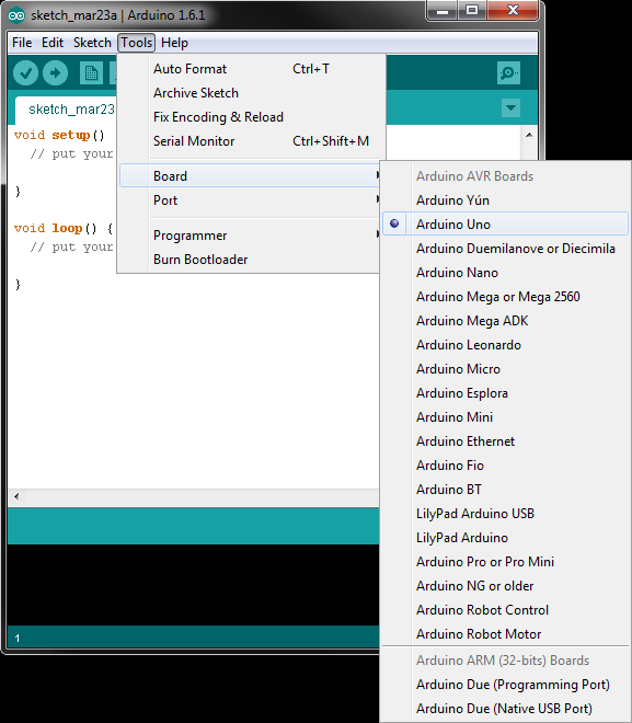
Open the Arduino IDE and select board:
Open the Arduino IDE software on your computer. This step is to set your IDE to identify your RedBot. You will want to select the board, Arduino Uno. To do this, go to Tools > Board > Arduino Uno.
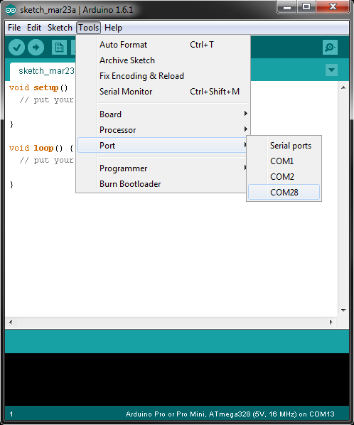
Select your Serial Port
Window users: Select the serial port for the RedBot from the Tools > Port menu. This is likely to be COM3 or higher (COM1 and COM2 are usually reserved for other internal devices). To check, disconnect your RedBot and re-open the menu; the entry that disappears is the one for the RedBot. Reconnect the board, and select that serial port.
Mac users: Select the serial device of the RedBot from the Tools > Serial Port menu. On the Mac, this should be something with /dev/tty.usbmodem or /dev/tty.usbserial in it. To find out, you can disconnect your RedBot and re-open the menu; the entry that disappears should be the RedBot. Reconnect the board and select that serial port.
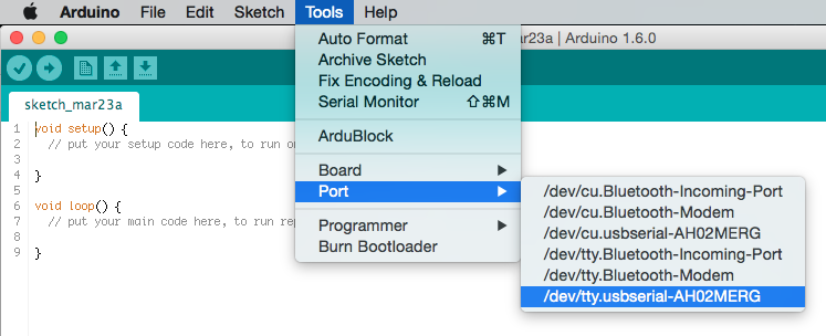
Note: If the Serial Port is not showing up, go back and re-install the FTDI drivers for your machine or try re-starting Arduino.
Experiment 1: Basic Test -- Hello World!
Time to make sure the electronics work! The "Hello World" of physical computing is generally a simple blink. On your RedBot Mainboard, there is a debug LED on pin 13. It's labeled on the board D13 LED.
We are going upload a simple program to the board to make sure everything is up and running.
Go to File > Examples > SparkFun RedBot Library > Exp1_BasicTest or copy and paste the example code below:
language:c
/***********************************************************************
 * Exp1_BasicTest -- RedBot Experiment 1
 *
 * Time to make sure the electronics work! To test everything out, we're
 * going to blink the LED on the board.
 *
 * This sketch was written by SparkFun Electronics, with lots of help from
 * the Arduino community.
 *
 * 23 Sept 2013 N. Seidle/M. Hord
 * 04 Oct 2014 B. Huang
 ***********************************************************************/

// setup() function runs once at the very beginning.
void setup()
{
  pinMode(13, OUTPUT); // The RedBot has an LED connected to pin 13.
  // Pins are all generic, so we have to first configure it
  // as an OUTPUT using this command.
}

// loop() function repeats over and over... forever!
void loop()
{
  // Blink sequence
  digitalWrite(13, HIGH); // Turns LED ON -- HIGH puts 5V on pin 13.
  delay(500);             // delay(500) "pauses" the program for 500 milliseconds
  digitalWrite(13, LOW);  // Turns LED OFF -- LOW puts 0V on pin 13.
  delay(500);             // delay(500) "pauses" the program for 500 milliseconds
  // The total delay period is 1000 ms, or 1 second.
}

/***********************************************************************
 * In Arduino, an LED is often connected to pin 13 for "debug" purposes.
 * This LED is used as an indicator to make sure that we're able to upload
 * code to the board. It's also a good indicator that your program is running.
 **********************************************************************/
What You Should See
Make sure the battery pack is plugged into the Mainboard, and turn the POWER switch to ON.

Click Upload in the Arduino IDE. The code will be compiled and converted into machine langage 1's and 0's. You should see two LEDs (TX and RX) blink rapidly back and forth - these indicate data being transmitted and received between the RedBot and your computer. After this is complete, you should see the D13 LED on the RedBot Mainboard flash on and off.
Learn More: LEDs
LEDs – short for light-emitting diodes – are the heart of every good, blinky electronics project. They are perfect for power indicators, debugging, or just adding a little zazz to your project.
LEDs have all sorts of light-related uses. You’re no-doubt used to seeing them in public displays (clocks, traffic lights, and signs) or as energy-efficient light-sources (flashlights, grocery store lighting, and accents), but they also have less obvious uses like infrared remote controls and computer mice.
In fact, recently the Nobel Prize in Physics was recently awarded to Isamu Akasaki, Hiroshi Amano and Shuji Nakamura for the invention of the Blue LED, which allows us to create white light with LEDs!
Code To Note
The RedBot has an LED connected to pin 13. Control of pin 13 can be accessed through the digitalWrite([pin], [HIGH\LOW]) command.
digitalWrite(13, HIGH) puts 5V on pin 13. In this case, this turns the LED on.
digitalWrite(13, LOW) puts 0V on pin 13, and turns the LED off.
The Arduino microcontroller runs at 16 MHz. This means it performs 16 Million operations per second. The digitalWrite() command takes less than 4 uS to execute. In order for us to see the LED turn on, we need to pause or delay the program flow. We do this with the command delay([time_ms]).
In our example, delay(500); 500 indicates the number of milliseconds the program is delayed for.
Going Further
Experiment around with the delay() function to change the rate of the blink. What is the fastest blink that you can still see? 10 ms? 20 ms?
Can you change the blink pattern to resemble a heart-beat? (Hint: You might need to add a second blink sequence to your loop.)
Troubleshooting
My code won't upload!
- Make sure your USB cable is plugged into both the robot and the computer you're using to write code.
- Make sure the "POWER" switch is switched to "ON."
- Double check that you have the right serial port selected under the "Tools" menu. The easiest way to check is to see which item disappears from the menu when you unplug the USB cable, and select that one when you plug the board back in.
- If you have an Xbee module plugged in, make sure the Serial Select switch at the top edge of the board is switched to "XBEE SW SERIAL."
- Check that you have the right board selected under the "Tools" menu. The RedBot is Arduino Uno-compatible, so select "Arduino Uno" from the list.
My motors aren't turning!
- This sketch does not turn on the motors; it just blinks. So, the motors should not be spinning.