Simon Splosion Wireless
 bri_huang
Introduction
Simon is an all-time classic game made by Milton Bradley. Kids have been playing this game for years - dating back to 1978. That's pretty impressive! I can't even imagine what kinds of electronics were available in 1978!
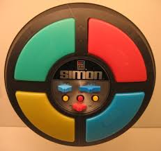
SparkFun created our own version of this game that now runs on the ATmega328 chip (the same microcontroller as the one on the Arduino Uno). This was originally designed as a simple soldering kit, but we quickly realized it had much more potential and could be used to teach programming as well. With a few header pins and an FTDI breakout, you can start reprogramming your Simon in Arduino.
Our basic game runs in a single-player mode. There have been many adaptations to the Simon Code - including a battle-mode that allows two players to challenge each other.
Easter Eggs?
If you haven’t discovered these yet - we have embedded two easter eggs into our code. The first is the Bee Gees Disco Mode. Hold down the Lower-Right button when you turn on the Simon to see this one.
There is also a "Battle-Mode" version that we programmed in as well. Hold the upper right button when you turn on the device. To start the game, the first player should hit a single button. Pass the Simon to your opponent. Your opponent repeats the button press, adds a second button, and then passes it back. Continue by mimicking the pattern and adding a new button for each round. This pattern repeats until someone loses.
Got it?
Wait! I bought my Simon Says kit a long time ago and it doesn't have this feature? No worries. We're going to show you how to update and modify your code.
Things you'll need to get started:
- At least one Simon Says PTH Kit
- FTDI Basic programmer
- USB Mini-B cable
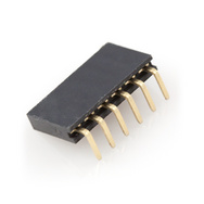
- These right-angle headers
You'll need a few more things to add wireless, but let's start with just making some easy modifications first.
Suggested Reading
Modifications
Step 1 -- Soldering Programming Headers
To program the Simon, we need access to the FTDI pins. Flip your Simon board upside down. To upload code, you will need to connect the silkscreen labelled GRN to GN and BLK to BLK.

|

|
There are six pins here. I like to solder these right-angle headers to the pins.
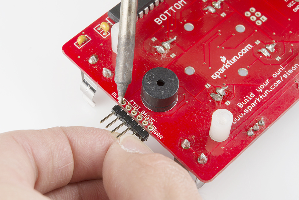
Alternatively, if you don’t have a soldering iron or you don’t want to solder, you can use straight pin headers. Just hold the connector in the holes while programming the device. The holes are what we call plated-through holes. This means that each hole has a cylinder of metal that connects to the pad. If you hold a straight pin header in at an angle, it should make a good electrical connection to the pins.
Step 2 -- Downloading the Default Example Code
If your Simon is an older version or if it doesn't have the two easter eggs, click here for the latest code from github. If you need a refresher on how to use GitHub, visit our tutorial.
Open / Unzip this file to your computer. Note: you must unzip the files in order to use them. Windows will often allow you to view the files within a compressed file, but you won't be able to access all of the files.
Under the folder \Simon-Says-master\Firmware\Simon_Says\ you should find the Arduino code -- Simon_Says.ino
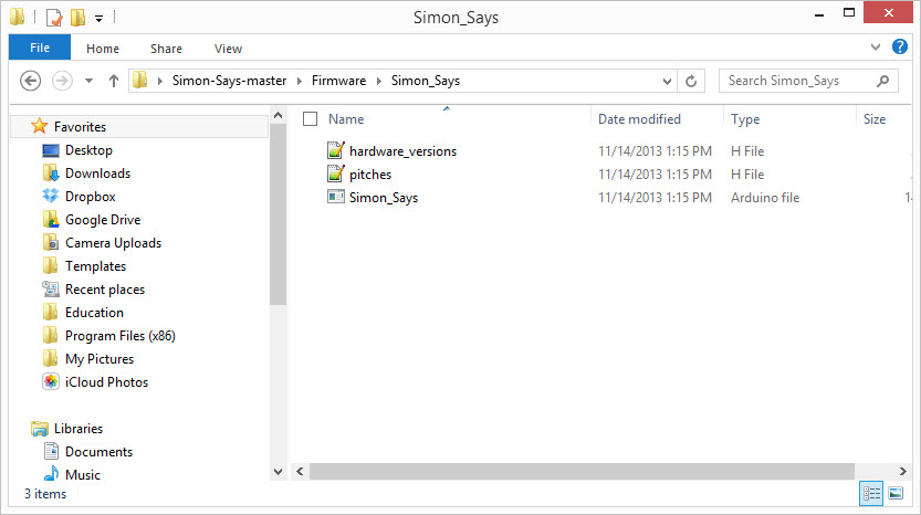
Open this file in Arduino.

Step 3 -- Upload to Simon Says
Using the FTDI Basic and your USB cable, connect the Simon to your computer.
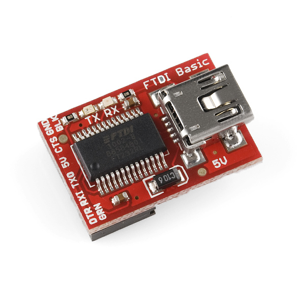
Be careful to line up the BLK and GRN markings on the FTDI Basic with the labels on the Simon.
Setting the Board Type
The Simon Says uses the LilyPad Arduino w/ ATMega328 bootloader. This is because we are using the internal oscillator on the ATMega328 instead of a separate crystal as on the Arduino Uno or on our RedBoard.
Under the Tools menu in Arduino, change the board type to Lilypad Arduino w/ ATMega328.
Select the proper Serial Port (generally the largest COM# for PCs and \dev\tty\usb-serialxxxx for Mac & Linux).
Make sure the Simon has batteries and is turned ON and click upload.
Now - remember there are two easter-eggs in this code. One is triggered by holding down the Lower-Right button when it turns on, the other is triggered by holding down the Upper-Right button.
Hacking the Simon Says Board
Now you're ready to start reprogramming your Simon.
A while back, we created a tutorial around tweaking the Simon Says board- https://www.sparkfun.com/tutorials/203. The images are of an older version but the experiments and documentation are all applicable to the current version of the Simon. You will also find example experiments to play around with here.
To help you out with hacking into the Simon Says board, here are a few notes about the LEDs, buttons, and the buzzer on the Plated Through Hole (PTH) Simon:
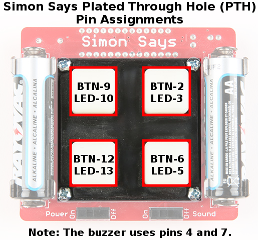
Pins 4 and 7 are tied to the buzzer. To use the tone() command, set both pin 4 and pin 7 as OUTPUTs, start with a digitalWrite(7, LOW), and use tone(4, freq); to drive the buzzer.
If you happened to get the SMD version of the Simon, the pin assignments are a little different. Here are the pin-outs for the LEDs and buttons on the Surface Mount Device (SMD) Simon:
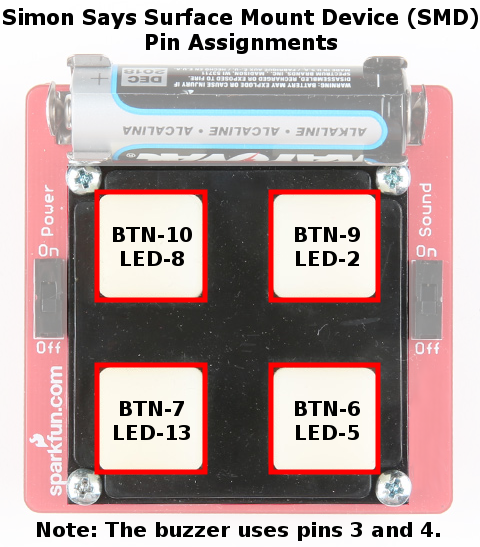
Buzzer is between pins 3 and 4.
If you're curious, check out Pete's tutorial and tinker around with the Simon. It has 4 buttons, 4 LEDs, a buzzer, and access to 6 additional I/O pins. What cool games or applications can you come up with for it? Be sure to share it back with us!
For now, we're going to show you how to add wireless XBee communication to your Simon Says.
Simon Says - Go Wireless (Part I)
Now that you have the latest firmware code on your Simon and you've challenged your friends at Battle-Mode Simon, what's next? Well, we thought it would be awesome to have a Wireless Battle-Mode version of the Simon game. So, we stepped things up and added an XBee wireless module to our device.
If you haven't played around with XBee, take a look at the materials from our Xciting Xbees class. For this we won't dig deep into the XBee side. In fact, we're going to just use two XBees with their standard factory settings. As a note - this will only work with two XBees in a single room. If you wish to have multiple Wireless Battle Simons you will need to configure and pair the XBees individually.
For now let's get started with hacking our Simon to go Wireless!
What you need:
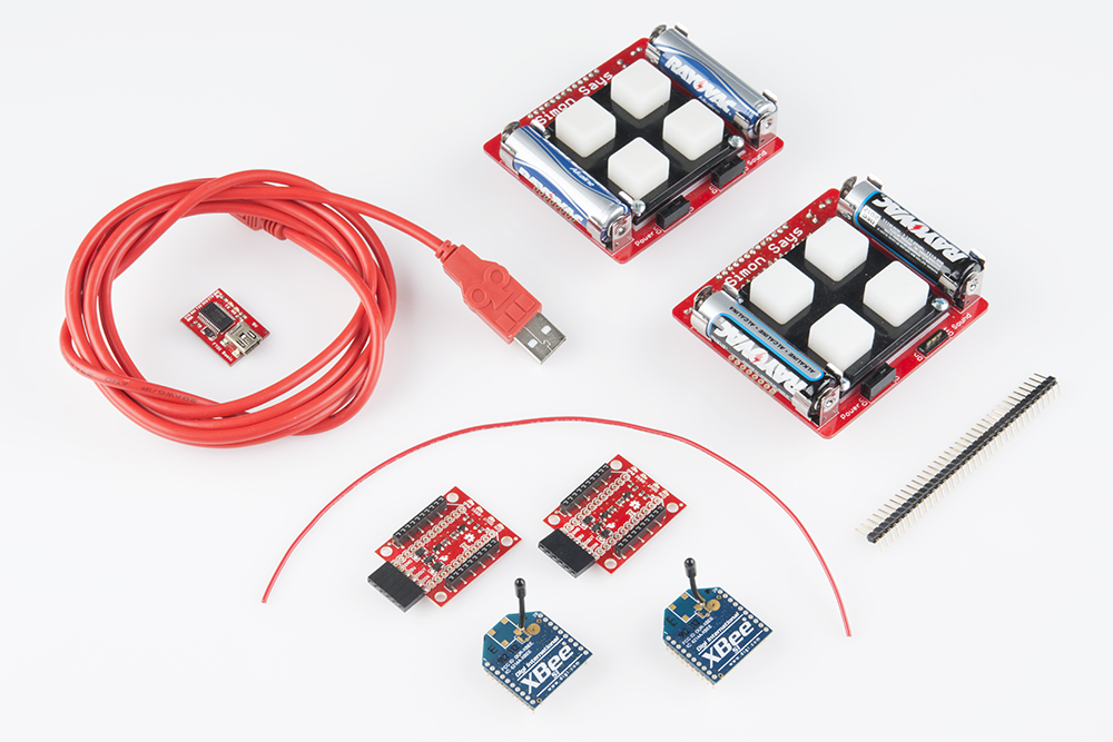
- 2x Simon Says PTH kits
- 2x XBee Wireless modules (Series 1 or Series 2)
- 2x XBee Xplorer
- 2x 6 pin female headers
- Solder / Soldering Iron
- Short length of 18 awg or smaller wire
- 1x Right angle Male headers
- FTDI Basic Breakout
Want to add this all to your shopping cart? Click here for the complete wishlist
Circuit Modifications / Soldering
Add male header pins to FTDI
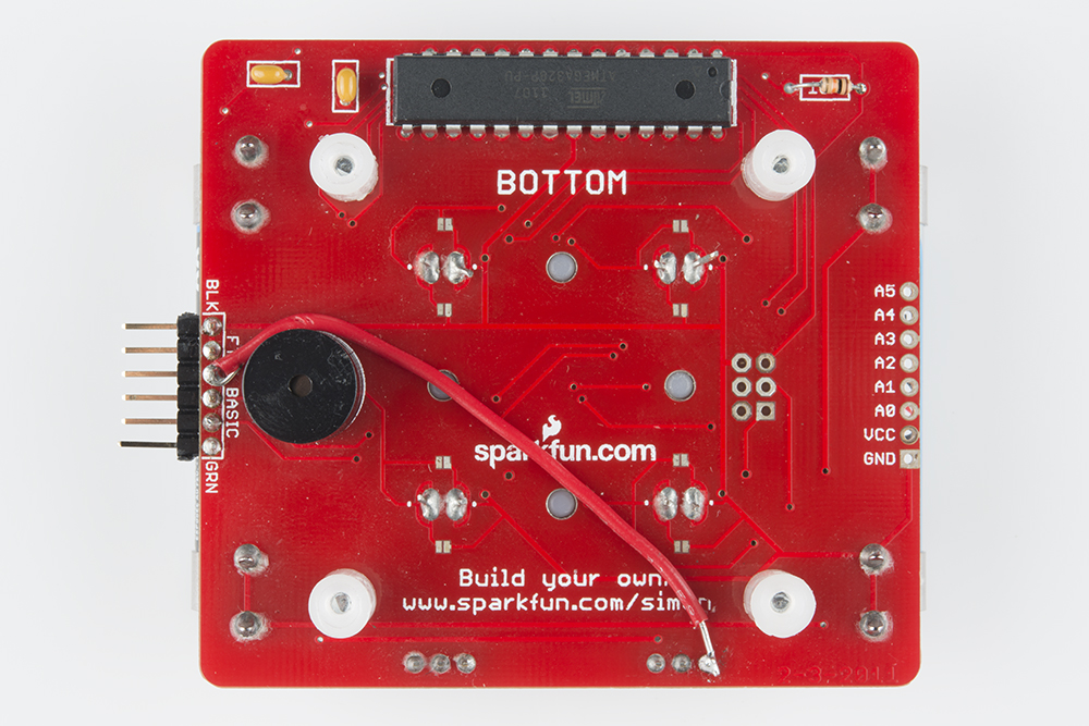
If you skipped ahead to this step make sure that you have male header pins soldered to the FTDI pins on the back of your Simon. Here's an image of one of the boards we did here:
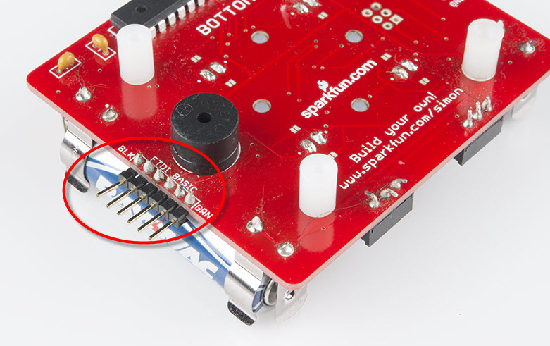
Generally, the FTDI header is tied to the main power of the board. For reasons I won't go into here, this was not done in our original board design. So, we need to add a small modification here. We need to solder a short length wire (~3 - 4 inches) from the Vcc (Power) pin on the FTDI header to the Vcc on the Simon.
Flip the Simon so that the side that you can see the side that says BOTTOM. Take a short length of solid core wire and solder this to the third pin from the top of the FTDI header (labeled BLK). If you look closely, you can see that I used needle-nose pliers to make a small hook on the end of the wire. I found this to be easier to hold the wire in place while I was soldering it. Be careful not to melt the buzzer housing while you're doing this. The buzzer is really close to these pins!
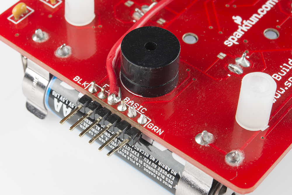
Now, take the other end of the wire and solder this to the outside pin on the POWER swtich (this is also the right side - when the board is upside down). It should look like this when you're done. I'd suggest using a slightly longer length of wire than I show here:
Repeat these steps for your other Simon.
New Firmware
If you haven't downloaded the firmware code yet, download it here from github.
Under the firmware subfolder there is a folder called Simon_Wireless. Open the file Simon_Wireless.ino and upload this to both of your Simons. Remember that the ATMega328 should be programmed using the LilyPad Arduino w/ ATMega328 board setting.
Simon Says - Go Wireless (Part II)
Now you have the headers soldered, the modifications made, and the new firmware on both of your Simons. Just a few more steps and you can start wirelessly battling Simon Says!
Configuring the XBees
The factory settings of the XBees will work for this tutorial as is. However, if you want to configure your XBees you will need to get an XBee USB Exporer. You can change the settings of the XBee with either AT Commands from a terminal window or using a program like XCTU.
If you change the settings just make sure that you have two XBees that are directly paired with each other.
Soldering headers to the XBee Explorer
The XBee Explorer comes unpopulated with header pins. So, we'll need to solder right angle female headers to this board.
 +
+ 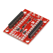
Solder the 6 pin right angle headers to the holes on the edge of the XBee Explorer. There should be exactly six pins there.
Let's Play!
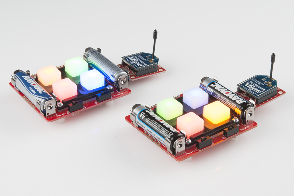
Plug the XBees into the FTDI header pins you soldered in earlier. Your two Simons should look like this:
How to play
Turn on both Simons. Each unit will power on and play an "attract" sequence of blinking LEDs. This will continue until one player presses a button. That player's unit will then go dark and wait for a first button in the sequence to be pressed. So, here's how to play:
- Player 1 – Hit any button to start.
- Player 1 – Hit first button to begin a pattern.
- Player 2 – Wait and watch the pattern to light up. Press the button that lights up, and add another button to the sequence.
- Player 1 - Repeat
This sequence will repeat over and over until one player makes a mistake. This unit will play the "You lost!" tune while the other unit will play the "Winner!" tune.
Want to modify or change the code? Well - you've got it. If you want the original program back, upload the Simon_Says.ino file.
Resources and Going Further
What's next? With an XBee and the Simon, you now have a remote controller. Use it to add remote control to a robot or to an LED Arduino project. Modify the code and use it to send messages to another Simon across a room! Maybe signal a partner when you're ready to leave a party?
For some project ideas, check out these other SparkFun tutorials: