Simon Splosion Wireless
 bri_huang
Simon Says - Go Wireless (Part I)
Now that you have the latest firmware code on your Simon and you've challenged your friends at Battle-Mode Simon, what's next? Well, we thought it would be awesome to have a Wireless Battle-Mode version of the Simon game. So, we stepped things up and added an XBee wireless module to our device.
If you haven't played around with XBee, take a look at the materials from our Xciting Xbees class. For this we won't dig deep into the XBee side. In fact, we're going to just use two XBees with their standard factory settings. As a note - this will only work with two XBees in a single room. If you wish to have multiple Wireless Battle Simons you will need to configure and pair the XBees individually.
For now let's get started with hacking our Simon to go Wireless!
What you need:
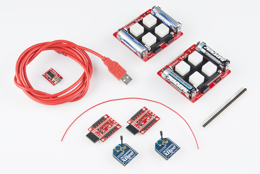
- 2x Simon Says PTH kits
- 2x XBee Wireless modules (Series 1 or Series 2)
- 2x XBee Xplorer
- 2x 6 pin female headers
- Solder / Soldering Iron
- Short length of 18 awg or smaller wire
- 1x Right angle Male headers
- FTDI Basic Breakout
Want to add this all to your shopping cart? Click here for the complete wishlist
Circuit Modifications / Soldering
Add male header pins to FTDI
If you skipped ahead to this step make sure that you have male header pins soldered to the FTDI pins on the back of your Simon. Here's an image of one of the boards we did here:
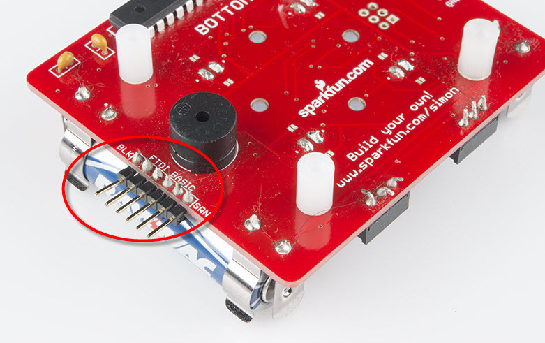
Generally, the FTDI header is tied to the main power of the board. For reasons I won't go into here, this was not done in our original board design. So, we need to add a small modification here. We need to solder a short length wire (~3 - 4 inches) from the Vcc (Power) pin on the FTDI header to the Vcc on the Simon.
Flip the Simon so that the side that you can see the side that says BOTTOM. Take a short length of solid core wire and solder this to the third pin from the top of the FTDI header (labeled BLK). If you look closely, you can see that I used needle-nose pliers to make a small hook on the end of the wire. I found this to be easier to hold the wire in place while I was soldering it. Be careful not to melt the buzzer housing while you're doing this. The buzzer is really close to these pins!
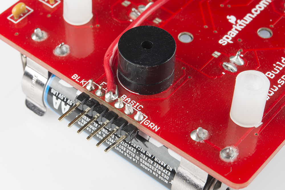
Now, take the other end of the wire and solder this to the outside pin on the POWER swtich (this is also the right side - when the board is upside down). It should look like this when you're done. I'd suggest using a slightly longer length of wire than I show here:
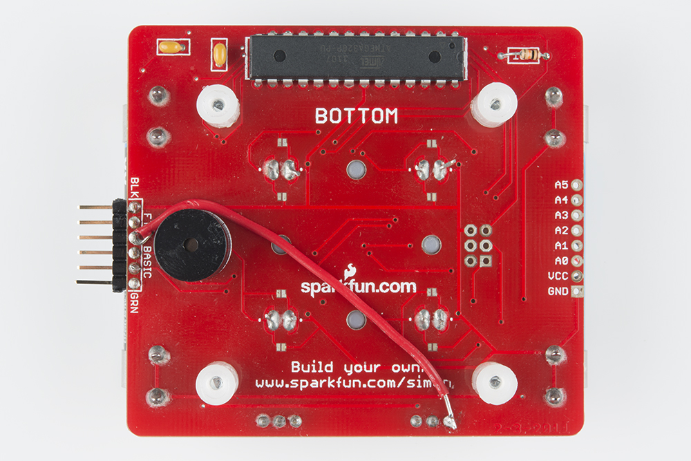
Repeat these steps for your other Simon.
New Firmware
If you haven't downloaded the firmware code yet, download it here from github.
Under the firmware subfolder there is a folder called Simon_Wireless. Open the file Simon_Wireless.ino and upload this to both of your Simons. Remember that the ATMega328 should be programmed using the LilyPad Arduino w/ ATMega328 board setting.