SparkFun Photodetector (MAX30101) Hookup Guide
Hardware Assembly
Arduino Examples
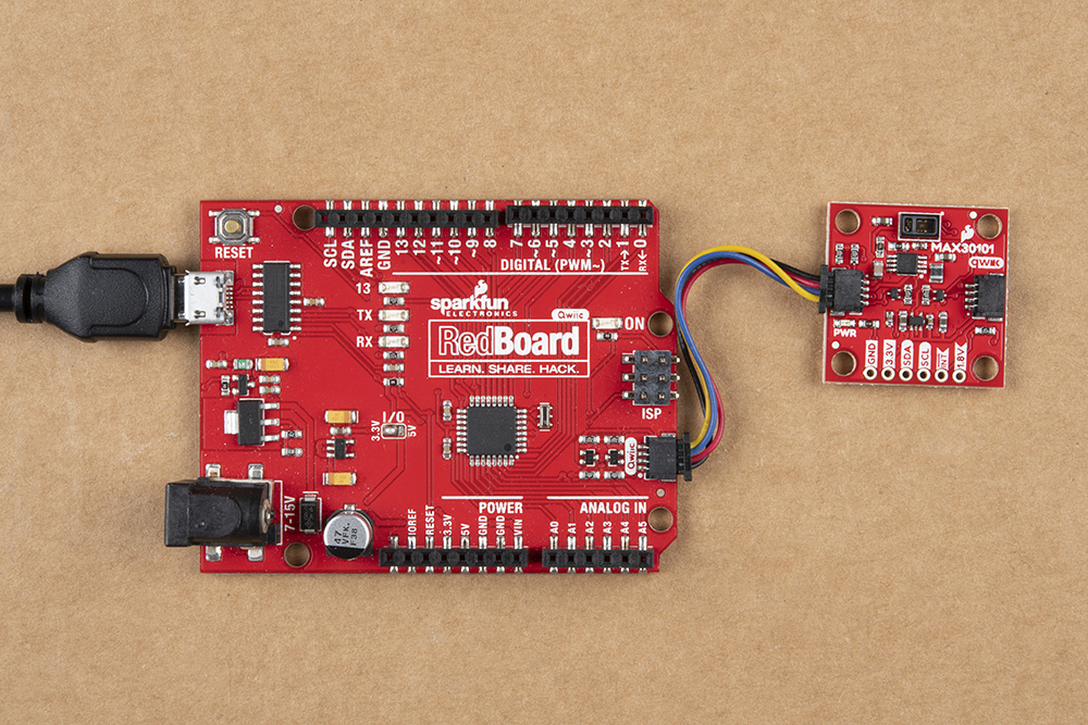
With the Qwiic connector system, assembling the hardware is simple. All you need to do is connect your SparkFun Photodetector -MAX30101 (Qwiic) to the RedBoard Qwiic with a Qwiic cable. Otherwise, you can use the I2C pins of your microcontroller; just be aware of logic levels.
Note: This tutorial assumes users are familiar with Arduino products and are using the latest stable version of the Arduino IDE on your desktop. If this is your first time using the Arduino IDE, please review our tutorial on installing the Arduino IDE.
Python Examples
With the Qwiic connector system, assembling the hardware is simple. In addition to the SparkFun Photodetector -MAX30101 (Qwiic), you will need: a Qwiic cable, a SparkFun Qwiic pHAT for Raspberry Pi, single board computer, monitor, and standard peripherals. (*If you are unfamiliar with the Qwiic pHAT, you can find the Hookup Guide here.)
There are two single board computer (SBC) options that we have tested on:
- Raspberry Pi setup with the Raspbian OS
- Jetson Nano running Nvidia's L4T image
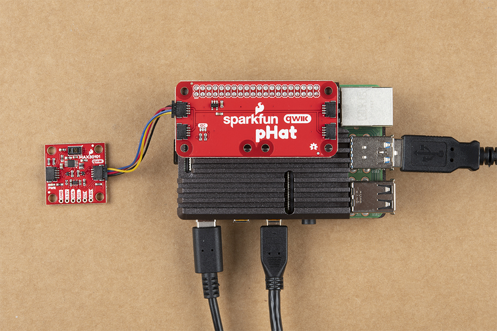
Raspberry Pi 4 (with heat sink case) connected the Qwiic Photodetector.
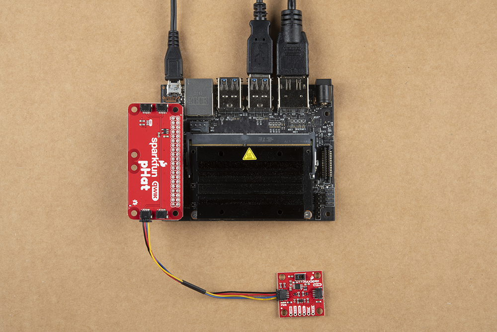 Jetson Nano connected the Qwiic Photodetector.
Note: This tutorial assumes users are familiar with using a Raspberry Pi and have the latest version of Raspbian OS (full... with recommended software) your Raspberry Pi. You can download the latest version of the Raspbian OS from the Raspberry Pi Foundation website.
If this is your first time using a Raspberry Pi, please head over to the Raspberry Pi Foundation website to use their quickstart guides. We have listed a few of them here:
Note: This tutorial assumes users are familiar with using a Jetson Nano and you have the latest version of L4T OS your Jetson Nano. You can download the latest version of the L4T OS from the Jetson Download Center on Nvidia's website.
If this is your first time using a Jetson Nano, please head over to the Nvidia website to use their quickstart guides. We have listed a few of them here:
Heart Beat Plotter and Heart Rate Examples
In both the Arduino and Python examples, there is are sample codes to demonstrate the MAX30101's biometric capability to detect a user's heart rate (or pulse). These are tricky examples to get working properly as the sensor can be finicky about the amount of pressure used along with the sensor's position on the finger.
Here are a few tips for users that may help:
- Relax in a comfortable position and keep you arm, hand, and finger as still as possible.
- A consistent amount of pressure should be used for more reliable readings.
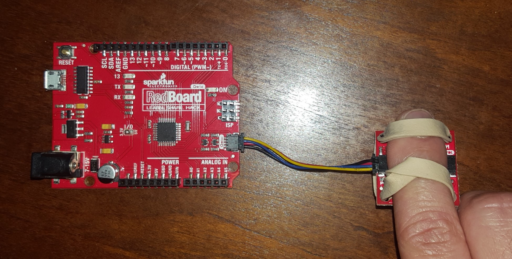
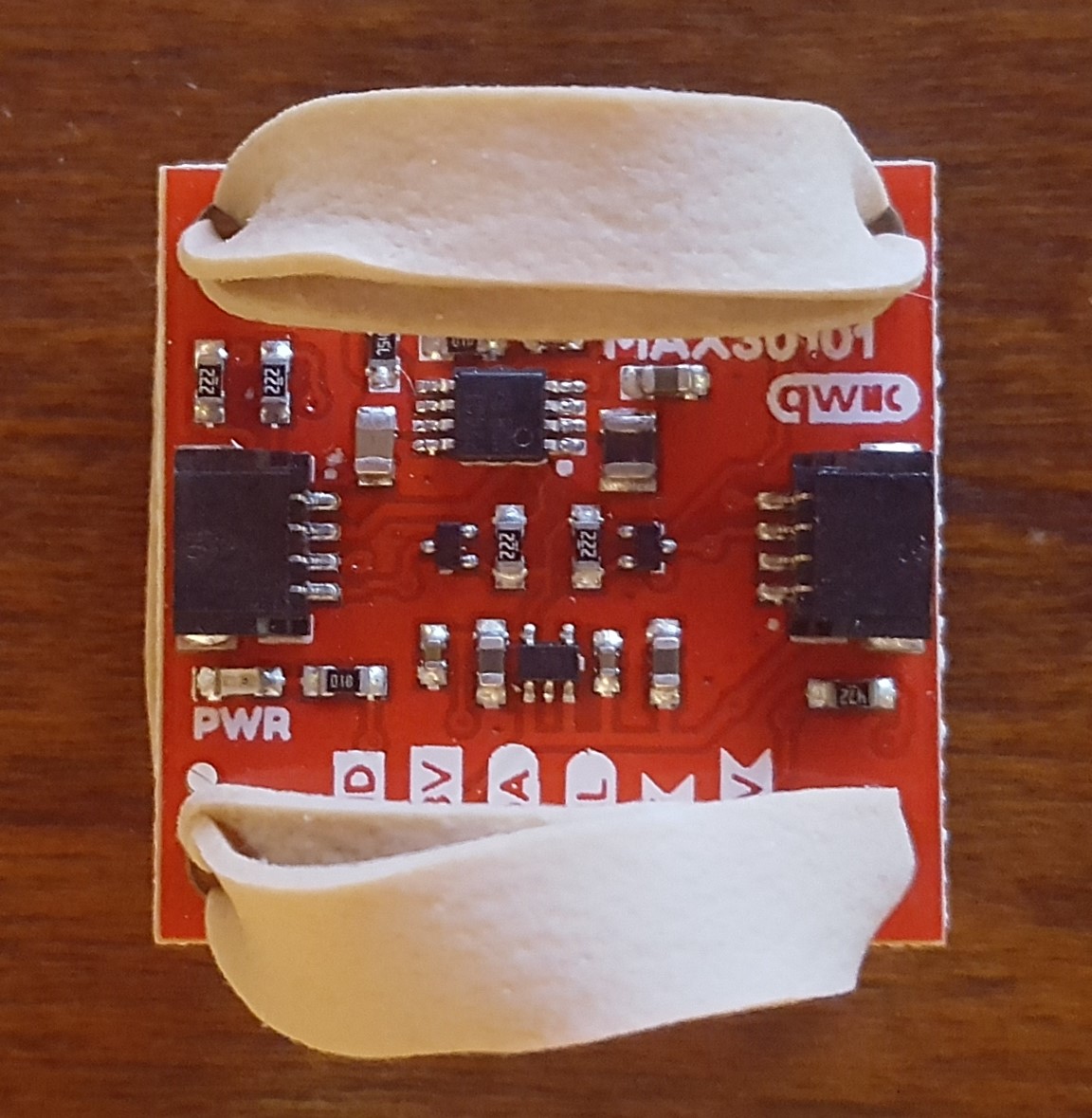
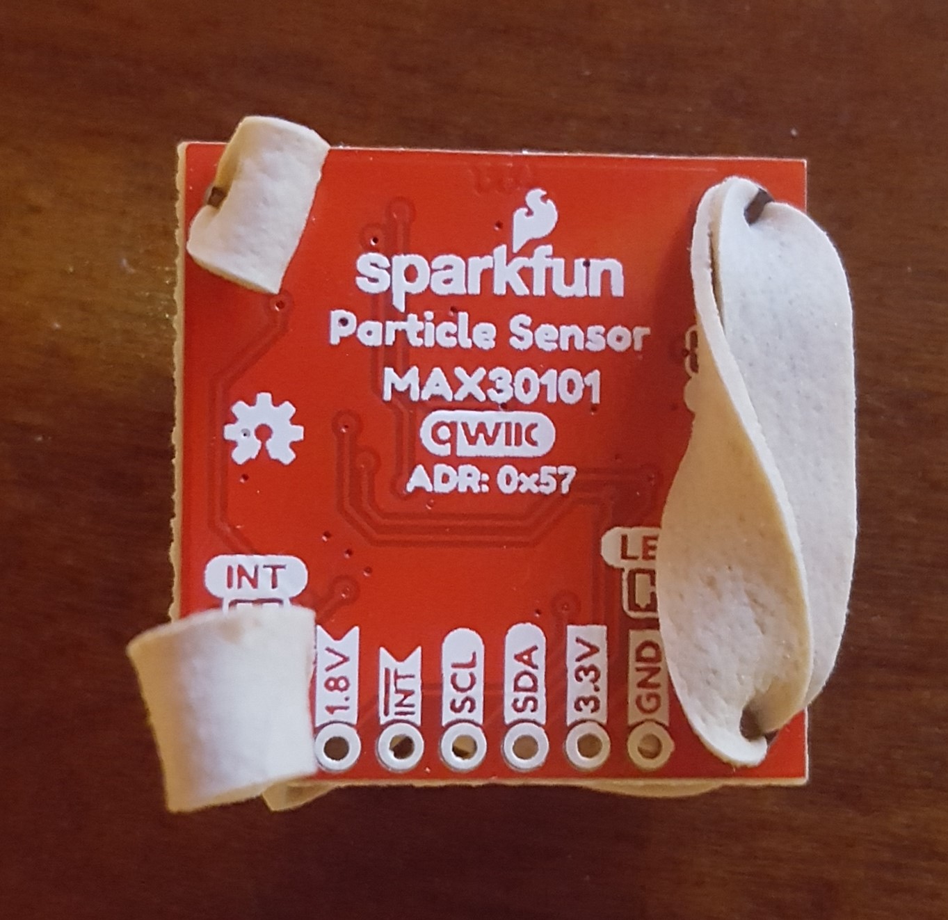
- Tape or a rubber band are recommended. The engineer for this product had the most success using a rubber band in this configuration:

 SparkFun Photodetector (MAX30101) with rubber band.
- Tape or a rubber band are recommended. The engineer for this product had the most success using a rubber band in this configuration:
- There is such a thing as too much pressure; use a fairly light amount of pressure. I found taping the board down, resting my arm on a table, and with just placing my finger's weight on the sensor worked fairly well for getting a consistent waveform.
- The photodetector on the MAX30101 is highly sensitive and light passing from above the finger can also affect the sensor readings.
- The sensor can be finicky for some users... and there isn't an easy way to troubleshoot this situation when you are getting poor readings. Keep trying. It took me 5 days of fiddling to get just the right combination of position and pressure for a proper reading. That being said, if you struggle that far, it will be a light bulb moment when you discover that combination and it becomes easier to repeat.
- Try to get the plotter working first, with the blips/bumps as that is how the heart rate example calculates your pulse.