SparkFun Photodetector (MAX30101) Hookup Guide
Introduction
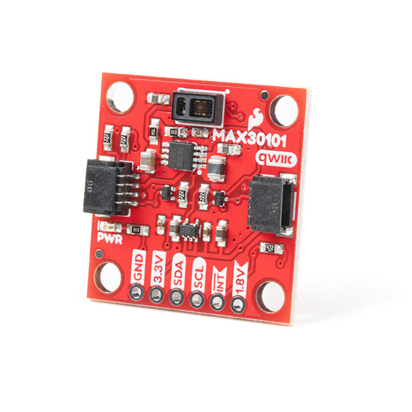
The SparkFun Photodetector - MAX30101 (Qwiic) is the successor to the MAX30105 particle sensor, a highly sensitive optical sensor. This tutorial will get you up and running to retrieve the raw data from the MAX30101 sensor.
The MAX30101 includes three LEDs and an optical detector in a single package, which can be utilized as a wearable, biosensor for pulse oximeter and heart-rate measurements. For accurate and reliable biometric readings, we recommend the SparkFun Pulse Oximeter and Heart Rate Sensor, which utilizes proprietary algorithms programmed on the MAX32664 Biometric Sensor Hub. Other possible applications include proximity sensing and particle detection by measuring the changes in light that is reflected back from the LEDs.
Required Materials
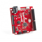
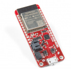
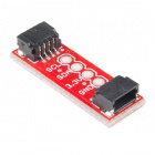
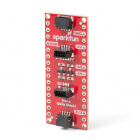
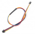
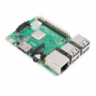
The Qwiic Photodetector Sensor does need a few additional items for you to get started. The RedBoard Qwiic will be used for the Arduino examples. A single board computer and the Qwiic pHAT are required for the Python examples (see note below). You may already have a few of these items, including the required Qwiic cable, so feel free to modify your cart based on your needs. Additionally, there are also alternative parts options that are available as well (click button below to toggle options).
SparkFun Thing Plus - ESP32 WROOM
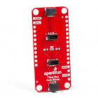
WRL-14689SparkFun Qwiic Shield for Arduino Nano
DEV-16130SparkFun Qwiic Shield for Thing Plus
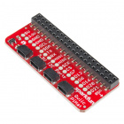
DEV-16138SparkFun Qwiic pHAT for Raspberry Pi
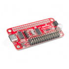
DEV-15351SparkFun Top pHAT for Raspberry Pi
DEV-16301Qwiic Cable - 100mm
PRT-14427Qwiic Cable - 50mm
PRT-14426Qwiic Cable - 200mm
PRT-14428Qwiic Cable - 500mm
PRT-14429pi-topCEED (Green)
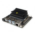
KIT-14035NVIDIA Jetson Nano Developer Kit (V3)
DEV-16271SparkFun DLI Kit (without Jetson Nano)
KIT-16389Rubber Band
Note: For the heart beat plotter examples, users will require a small to medium size rubber band.
Suggested Reading
If you're unfamiliar with serial terminals, jumper pads, or I2C be sure to checkout some of these foundational tutorials. The MAX30105 is designed for a handful of uses including Pulse Oximetry. If you're unfamiliar with optical pulse detection there are some very good application notes from TI and NXP that have great starter information.
Installing an Arduino Library
Logic Levels
I2C
Serial Terminal Basics
MAX30105 Particle and Pulse Ox Sensor Hookup Guide
How to Work with Jumper Pads and PCB Traces
RedBoard Qwiic Hookup Guide
SparkFun Pulse Oximeter and Heart Rate Monitor Hookup Guide
Raspberry Pi SPI and I2C Tutorial
Python Programming Tutorial: Getting Started with the Raspberry Pi
Qwiic pHAT for Raspberry Pi Hookup Guide
Working with Qwiic on a Jetson Nano through Jupyter Notebooks
The Qwiic Photodetector utilizes the Qwiic connect system. We recommend familiarizing yourself with the Logic Levels and I2C tutorials (above) before using it. Click on the banner above to learn more about our Qwiic products.
Note: First time Raspberry Pi users should also head over to the Raspberry Pi Foundation website and check out their quickstart guides:
- Blog Post: Getting started with your Raspberry Pi
- Raspberry Pi Foundation Getting Stared Guides:
- MagPi Books and Guides:
- Article: Get started with your new Raspberry Pi
- The Offical Raspberry Pi Beginner’s Book (December 2017)
- Get Started with Raspberry Pi (November 2019)
- The Offical Raspberry Pi Beginner’s Guide: How to use your new computer
1st Edition (December 2018)
2nd Edition (June 2019)
3rd Edition (November 2019)
We have also listed a few additional resources for users to familiarize themselves with the Raspberry Pi:
Note: First time Nvidia Jetson Nano users should also head over to the Nvidia website and check out their guides and tutorials:
Hardware Overview
Dimensions
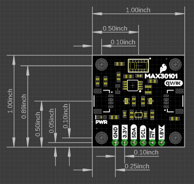
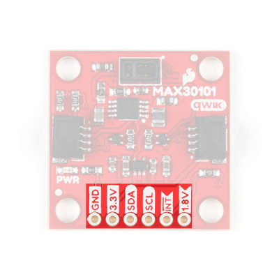
The Qwiic Photodetector Sensor is laid out on the standardized 1" x 1" (2.54 x 2.54 cm) Qwiic breakout board and includes the standard four 0.13" mounting holes, which are compatible with M3 screws.
Power LED
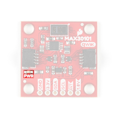
There is a power status LED to help make sure that your Qwiic Photodetector Sensor is getting power. You can power the board either through the polarized Qwiic connector system or the breakout pins (3.3V and GND) provided. The Qwiic system is meant to run on 3.3V, be sure that you are NOT using another voltage when using the Qwiic system. A jumper is available on the back of the board to remove power to the LED for low-power applications (see Jumpers section below).
MAX30101
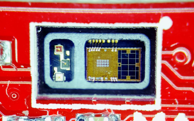
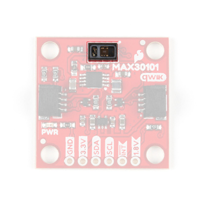
The MAX30101 includes three LEDs and an optical detector in a single package. Behind the window on the left, are red, green, and IR LEDs. While behind the window on the right, is a highly sensitive photon detector.
The working principle of the sensor is that the optical detector measures the changes in the reflected light that was emitted from the LEDs. This is great for various application like detecting particles or for photoplethysmography.
(*For more details on the MAX30101, users can check out the datasheet.)
| Characteristic | Description |
|---|---|
| Power |
Supply Voltage: 1.7 - 2.0V Supply Cuurent: 0.6 - 1.1mA LED Driver:
|
| ADC | Resolution: 18-bits (65536 Counts) |
| LEDs |
Wavelength:
Power:
|
| Photodetector | Spectral Range: 640 - 980nm |
| Temperature Sensor |
Range: -40 - 85°C Accuracy: ±1°C |
| I2C Address | 0x57 |
Application Notes
Note: Particle detection, heart rate measurement, and photoplethysmography (for pulse oximetry) are applications of the MAX30101. These applications are detailed in the notes below; however, they require an understanding of the operating principles of the sensor and a conceptual knowledge of the application(s). Although, we provided the information below for interested users and may provide some examples of the application in our software; these applications are, unfortunately, not supported by SparkFun and the examples are primarily for demonstration purposes only.
Here are additional resources on how the MAX30101 functions for HR detection and pulse oximetry:
- Basic Concept: The sensor relies on the reflection and scattering of the red and IR light that penetrates into the subcutaneous tissue.
- Penetration Depth Guide For Biosensor Applications
- Guidelines for SpO2 Measurement Using the Maxim® MAX32664 Sensor Hub
- Recommended Configurations and Operating Profilesfor MAX30101/MAX30102 EV Kits
- Multi-wavelength photoplethysmography method for skin arterial pulse extraction
- Signal-to-Noise Ratio as a Quantitative Measure for Optical Biosensors
For more information on particulate matter and their detection, check out these resources:
- Basic Concept: The sensor relies on the reflection and scattering of the red and IR light from particles to detect their presence.
Maxim's Original Firmware for the MAX30102 adapted in our Arduino Library:
- MAXREFDES117 firmware for Arduino platforms
- Video Demonstration of the MAX30102 using the firmware above (video courtesy of Maxim Integrated.):
Qwiic and I2C
I2C Address
The Qwiic Photodetector Sensor’s I2C address, 0x57, is factory set.
Qwiic Connectors
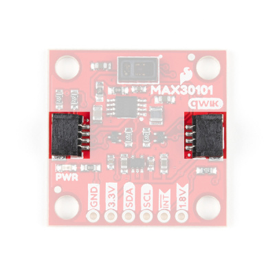
The simplest way to use the Qwiic Photodetector Sensor is through the Qwiic connect system. The connectors are polarized for the I2C connection and power. (*They are tied to the corresponding power and I2C breakout pins.)
Breakout Pins
The board also provides six labeled breakout pins. You can connect these lines to the I2C bus of your microcontroller and power pins (3.3V and GND), if it doesn't have a Qwiic connector. The interrupt pin is also broken out to use for triggered events.
Interrupt Pin
The interrupt pins (active high) are used to indicate various states of the ADXL313, depending on how they are configured and if they are enabled. The INT pins are pulled down with a 4.7kΩ resistor.
Jumpers
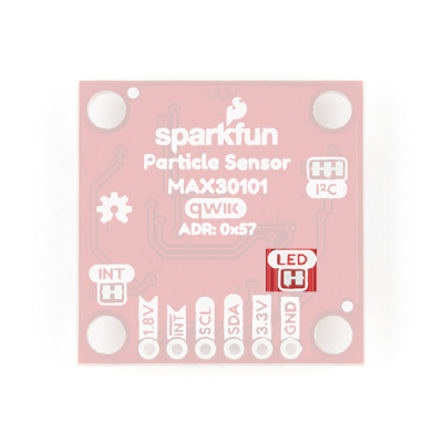
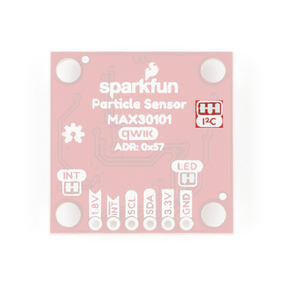
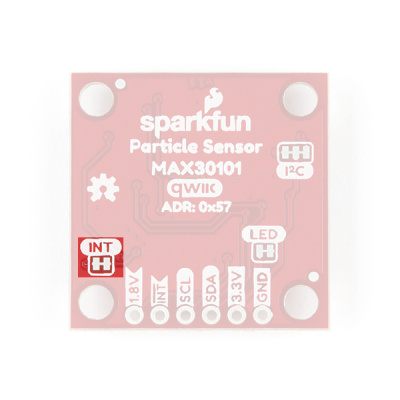
There are three jumpers on the board. Not sure how to cut a jumper? Read here!
Power LED
Cutting the LED jumper will remove the 1kΩ resistors and PWR LED from the 3.3V power. This is useful for low power applications
I2C Pull-Up
Cutting the I2C jumper will remove the 2.2kΩ pull-up resistors from the I2C bus. If you have many devices on your I2C bus you may want to remove these jumpers. Be aware that these resistors are also part of the transistor logic level shifting circuit.
Interrupt Pull-up
Cutting the INT jumper will remove the 4.7kΩ pull-up resistors from the interrupt pin.
Hardware Assembly
Arduino Examples
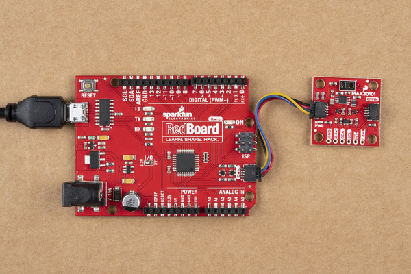
With the Qwiic connector system, assembling the hardware is simple. All you need to do is connect your SparkFun Photodetector -MAX30101 (Qwiic) to the RedBoard Qwiic with a Qwiic cable. Otherwise, you can use the I2C pins of your microcontroller; just be aware of logic levels.
Note: This tutorial assumes users are familiar with Arduino products and are using the latest stable version of the Arduino IDE on your desktop. If this is your first time using the Arduino IDE, please review our tutorial on installing the Arduino IDE.
Python Examples
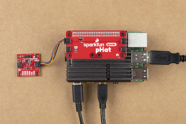
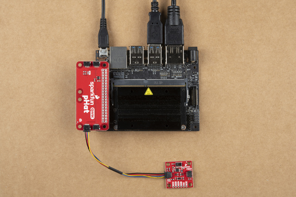
With the Qwiic connector system, assembling the hardware is simple. In addition to the SparkFun Photodetector -MAX30101 (Qwiic), you will need: a Qwiic cable, a SparkFun Qwiic pHAT for Raspberry Pi, single board computer, monitor, and standard peripherals. (*If you are unfamiliar with the Qwiic pHAT, you can find the Hookup Guide here.)
There are two single board computer (SBC) options that we have tested on:
- Raspberry Pi setup with the Raspbian OS
- Jetson Nano running Nvidia's L4T image
Note: This tutorial assumes users are familiar with using a Raspberry Pi and have the latest version of Raspbian OS (full... with recommended software) your Raspberry Pi. You can download the latest version of the Raspbian OS from the Raspberry Pi Foundation website.
If this is your first time using a Raspberry Pi, please head over to the Raspberry Pi Foundation website to use their quickstart guides. We have listed a few of them here:
Note: This tutorial assumes users are familiar with using a Jetson Nano and you have the latest version of L4T OS your Jetson Nano. You can download the latest version of the L4T OS from the Jetson Download Center on Nvidia's website.
If this is your first time using a Jetson Nano, please head over to the Nvidia website to use their quickstart guides. We have listed a few of them here:
Heart Beat Plotter and Heart Rate Examples
In both the Arduino and Python examples, there is are sample codes to demonstrate the MAX30101's biometric capability to detect a user's heart rate (or pulse). These are tricky examples to get working properly as the sensor can be finicky about the amount of pressure used along with the sensor's position on the finger.
Here are a few tips for users that may help:
- Relax in a comfortable position and keep you arm, hand, and finger as still as possible.
- A consistent amount of pressure should be used for more reliable readings.
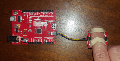
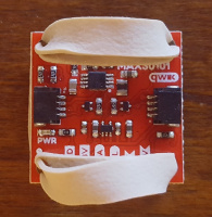
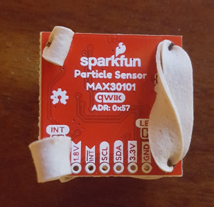
- Tape or a rubber band are recommended. The engineer for this product had the most success using a rubber band in this configuration:
SparkFun Photodetector (MAX30101) with rubber band.
- Tape or a rubber band are recommended. The engineer for this product had the most success using a rubber band in this configuration:
- There is such a thing as too much pressure; use a fairly light amount of pressure. I found taping the board down, resting my arm on a table, and with just placing my finger's weight on the sensor worked fairly well for getting a consistent waveform.
- The photodetector on the MAX30101 is highly sensitive and light passing from above the finger can also affect the sensor readings.
- The sensor can be finicky for some users... and there isn't an easy way to troubleshoot this situation when you are getting poor readings. Keep trying. It took me 5 days of fiddling to get just the right combination of position and pressure for a proper reading. That being said, if you struggle that far, it will be a light bulb moment when you discover that combination and it becomes easier to repeat.
- Try to get the plotter working first, with the blips/bumps as that is how the heart rate example calculates your pulse.
Arduino Library
Note: This example assumes you are using the latest version of the Arduino IDE on your desktop. If this is your first time using Arduino, please review our tutorial on installing the Arduino IDE. If you have not previously installed an Arduino library, please check out our installation guide.
(*Users can also check out the steps shown in the MAX30105 hookup guide. For the heart beat plotter example, the Arduino IDE must be version 1.6.6 or higher.)
We've written a library to easily get setup and take readings from the SparkFun Photodetector -MAX30101 (Qwiic). However, before we jump into getting data from the sensor, let's take a closer look at the available functions in the library. You can install this library through the Arduino Library Manager. Search for SparkFun MAX3010X Arduino Library and you should be able to install the latest version. If you prefer manually downloading the libraries from the GitHub repository, you can grab them here:
Let's get started by looking at the functions that set up the Qwiic Atmospheric Sensor:
Class
In the global scope, construct your sensor object (such as mySensor) without arguments.
MAX30105 mySensor;
Object Parameters and setup()
Rather that passing a bunch of data to the constructor, configuration is accomplished by setting the values of the MAX30105 type in the setup() function. They are exposed by being public: so use the myName.aVariable = someValue; syntax.
Settable variables of the class MAX30105:
language:c
// Status Registers
uint8_t MAX30105_INTSTAT1 =     0x00;
uint8_t MAX30105_INTSTAT2 =     0x01;
uint8_t MAX30105_INTENABLE1 =       0x02;
uint8_t MAX30105_INTENABLE2 =       0x03;

// FIFO Registers
uint8_t MAX30105_FIFOWRITEPTR =     0x04;
uint8_t MAX30105_FIFOOVERFLOW =     0x05;
uint8_t MAX30105_FIFOREADPTR =  0x06;
uint8_t MAX30105_FIFODATA =     0x07;

// Configuration Registers
uint8_t MAX30105_FIFOCONFIG =       0x08;
uint8_t MAX30105_MODECONFIG =       0x09;
uint8_t MAX30105_PARTICLECONFIG =   0x0A;    // Note, sometimes listed as "SPO2" config in datasheet (pg. 11)
uint8_t MAX30105_LED1_PULSEAMP =    0x0C;
uint8_t MAX30105_LED2_PULSEAMP =    0x0D;
uint8_t MAX30105_LED3_PULSEAMP =    0x0E;
uint8_t MAX30105_LED_PROX_AMP =     0x10;
uint8_t MAX30105_MULTILEDCONFIG1 = 0x11;
uint8_t MAX30105_MULTILEDCONFIG2 = 0x12;

// Die Temperature Registers
uint8_t MAX30105_DIETEMPINT =       0x1F;
uint8_t MAX30105_DIETEMPFRAC =  0x20;
uint8_t MAX30105_DIETEMPCONFIG =    0x21;

// Proximity Function Registers
uint8_t MAX30105_PROXINTTHRESH =    0x30;

// Part ID Registers
uint8_t MAX30105_REVISIONID =       0xFE;
uint8_t MAX30105_PARTID =           0xFF;    // Should always be 0x15. Identical to MAX30102.

// MAX30105 Commands
// Interrupt configuration (pg 13, 14)
uint8_t MAX30105_INT_A_FULL_MASK =      (byte)~0b10000000;
uint8_t MAX30105_INT_A_FULL_ENABLE =    0x80;
uint8_t MAX30105_INT_A_FULL_DISABLE =   0x00;

uint8_t MAX30105_INT_DATA_RDY_MASK = (byte)~0b01000000;
uint8_t MAX30105_INT_DATA_RDY_ENABLE =  0x40;
uint8_t MAX30105_INT_DATA_RDY_DISABLE = 0x00;

uint8_t MAX30105_INT_ALC_OVF_MASK = (byte)~0b00100000;
uint8_t MAX30105_INT_ALC_OVF_ENABLE =   0x20;
uint8_t MAX30105_INT_ALC_OVF_DISABLE = 0x00;

uint8_t MAX30105_INT_PROX_INT_MASK = (byte)~0b00010000;
uint8_t MAX30105_INT_PROX_INT_ENABLE = 0x10;
uint8_t MAX30105_INT_PROX_INT_DISABLE = 0x00;

uint8_t MAX30105_INT_DIE_TEMP_RDY_MASK = (byte)~0b00000010;
uint8_t MAX30105_INT_DIE_TEMP_RDY_ENABLE = 0x02;
uint8_t MAX30105_INT_DIE_TEMP_RDY_DISABLE = 0x00;

uint8_t MAX30105_SAMPLEAVG_MASK =   (byte)~0b11100000;
uint8_t MAX30105_SAMPLEAVG_1 =  0x00;
uint8_t MAX30105_SAMPLEAVG_2 =  0x20;
uint8_t MAX30105_SAMPLEAVG_4 =  0x40;
uint8_t MAX30105_SAMPLEAVG_8 =  0x60;
uint8_t MAX30105_SAMPLEAVG_16 =     0x80;
uint8_t MAX30105_SAMPLEAVG_32 =     0xA0;

uint8_t MAX30105_ROLLOVER_MASK =    0xEF;
uint8_t MAX30105_ROLLOVER_ENABLE = 0x10;
uint8_t MAX30105_ROLLOVER_DISABLE = 0x00;

uint8_t MAX30105_A_FULL_MASK =  0xF0;

// Mode configuration commands (page 19)
uint8_t MAX30105_SHUTDOWN_MASK =    0x7F;
uint8_t MAX30105_SHUTDOWN =         0x80;
uint8_t MAX30105_WAKEUP =           0x00;

uint8_t MAX30105_RESET_MASK =       0xBF;
uint8_t MAX30105_RESET =            0x40;

uint8_t MAX30105_MODE_MASK =        0xF8;
uint8_t MAX30105_MODE_REDONLY =     0x02;
uint8_t MAX30105_MODE_REDIRONLY =   0x03;
uint8_t MAX30105_MODE_MULTILED =    0x07;

// Particle sensing configuration commands (pgs 19-20)
uint8_t MAX30105_ADCRANGE_MASK =    0x9F;
uint8_t MAX30105_ADCRANGE_2048 =    0x00;
uint8_t MAX30105_ADCRANGE_4096 =    0x20;
uint8_t MAX30105_ADCRANGE_8192 =    0x40;
uint8_t MAX30105_ADCRANGE_16384 =   0x60;

uint8_t MAX30105_SAMPLERATE_MASK = 0xE3;
uint8_t MAX30105_SAMPLERATE_50 =    0x00;
uint8_t MAX30105_SAMPLERATE_100 =   0x04;
uint8_t MAX30105_SAMPLERATE_200 =   0x08;
uint8_t MAX30105_SAMPLERATE_400 =   0x0C;
uint8_t MAX30105_SAMPLERATE_800 =   0x10;
uint8_t MAX30105_SAMPLERATE_1000 = 0x14;
uint8_t MAX30105_SAMPLERATE_1600 = 0x18;
uint8_t MAX30105_SAMPLERATE_3200 = 0x1C;

uint8_t MAX30105_PULSEWIDTH_MASK = 0xFC;
uint8_t MAX30105_PULSEWIDTH_69 =    0x00;
uint8_t MAX30105_PULSEWIDTH_118 =   0x01;
uint8_t MAX30105_PULSEWIDTH_215 =   0x02;
uint8_t MAX30105_PULSEWIDTH_411 =   0x03;

//Multi-LED Mode configuration (pg 22)
uint8_t MAX30105_SLOT1_MASK =       0xF8;
uint8_t MAX30105_SLOT2_MASK =       0x8F;
uint8_t MAX30105_SLOT3_MASK =       0xF8;
uint8_t MAX30105_SLOT4_MASK =       0x8F;

uint8_t SLOT_NONE =                 0x00;
uint8_t SLOT_RED_LED =          0x01;
uint8_t SLOT_IR_LED =               0x02;
uint8_t SLOT_GREEN_LED =            0x03;
uint8_t SLOT_NONE_PILOT =           0x04;
uint8_t SLOT_RED_PILOT =            0x05;
uint8_t SLOT_IR_PILOT =             0x06;
uint8_t SLOT_GREEN_PILOT =      0x07;

uint8_t MAX_30105_EXPECTEDPARTID = 0x15;
Functions
The MAX30101 is highly configurable, and there are a large number of functions exposed in the library to the user. Checkout the MAX30105.h file for all the functions, but here are the major ones. Read the MAX30101 datasheet for more information.
The library supports the following functions:
.begin(wirePort, i2cSpeed)- If you have a platform with multiple I2C ports, pass the port object when you call begin. You can increase the I2C speed to 400kHz by including I2C_SPEED_FAST when you call.begin()as well..setup()- Initializes the sensor with various settings. See the Example 2 from the MAX30105 hookup guide for a good explanation of the options..getRed()- Returns the immediate red value.getIR()- Returns the immediate IR value.getGreen()- Returns the immediate Green value.available()- Returns how many new samples are available.readTemperature()- Returns the temperature of the IC in C.readTemperatureF()- Returns the temperature of the IC in F.softReset()- Resets everything including data and configuration.shutDown()- Powers down the IC but retains all configuration.wakeUp()- Opposite of shutDown.setLEDMode(mode)- Configure the sensor to use 1 (Red only), 2 (Red + IR), or 3 (Red + IR + Green) LEDs.setADCRange(adcRange)- Set ADC to be at 2048, 4096, 8192, or 16384.setSampleRate(sampleRate)- Configure the sample rate: 50, 100, 200, 400, 800, 1000, 1600, 3200
Interrupts
.getINT1()- Returns the main interrupt group.getINT2()- Returns the temp ready interrupt- Enable/disable individual interrupts. See page 13 and 14 of the datasheet for an explanation of each interrupt:
.enableAFULL().disableAFULL().enableDATARDY().disableDATARDY().enableALCOVF().disableALCOVF().enablePROXINT().disablePROXINT().enableDIETEMPRDY().disableDIETEMPRDY()
FIFO
The MAX30101 has a 32 byte FIFO (first-in first-out) buffer. This allows us do other things on our microcontroller while the sensor is taking measurements.
.check()- Call regularly to pull data in from sensor.nextSample()- Advances the FIFO.getFIFORed()- Returns the FIFO sample pointed to by tail.getFIFOIR()- Returns the FIFO sample pointed to by tail.getFIFOGreen()- Returns the FIFO sample pointed to by tail
Arduino Examples
☠ Do not rely on our examples for medical diagnosis or any life saving applications
Note: Particle detection, heart rate measurement, and photoplethysmography (for pulse oximetry) are applications of the MAX30101. These applications require a fundamental understanding of the operating principles of the sensor and a conceptual knowledge of the applications. Although, we provide some examples for these applications; they are primarily for demonstration purposes only and are not supported by SparkFun.
Note: Although there is an example, Maxim has since removed the proximity sensing and particle detection as functionalities of this sensor in their datasheet.
Example 1 - Reading Red/IR/Green
Once you've got the library installed, open the Example1 Basic Readings sketch. You can find it under
File > Examples > SparkFun MAX3010x Pulse and Proximity Sensor Library > Examples
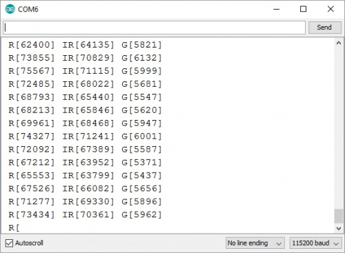
Then load it onto your RedBoard or Uno. Open your favorite Serial Terminal to see the printed values.
This example outputs the raw values read by the sensor. With the sensor pointing up, use your hand to hover over the sensor. You should see a change in values as your hand reflects different amounts of light. Note that the IR readings will probably change before the Red and Green readings. IR is better at sensing distance changes.
Completely cover the sensor with your finger. Note the very large readings. This is one of the features that sets the MAX30101 from other reflectance sensors. The IC is capable of reading up to 18-bits or values up to 262,144. An extremely small change in light can be detected!
The MAX30101 is easy to use! Calling particleSensor.getGreen() will take a reading and return the reflected amount of green light.
Example 3 - Temperature Sensor
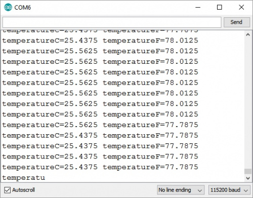
Open the Example3 Temperature Sense sketch, and load it onto your RedBoard or Uno.
This example outputs readings from the on-board temperature sensor in both Celsius and Fahrenheit. The temp sensor is accurate to ±1 °C but has an astonishing precision of 0.0625 °C.
The temperature is used internally by the sensor to calibrate its samples but can be useful if you need a sensitive and fast responding temp sensor.
Example 4 - Heart Beat Plotting
For this demo, you'll need a rubber band small enough to go through the mounting holes on the breakout. Make sure to follow the example in the Hardware Assembly section for the best results.
This is where the fun really begins! Hemoglobin reflects IR light really well, and the MAX30101 is capable of detecting such small changes in IR reflectance that it can detect blood flowing through your finger at different rates. Let's graph it! Open the Example4 HeartBeat Plotter sketch, and load it on your Redboard or Uno.
Instructions:
- Load code onto Redboard
- Attach sensor to your finger with a rubber band
- Open Tools->Serial Plotter
- Make sure the drop down is set to 115200 baud
- Checkout the blips!
- Feel the pulse on your neck and watch it mimic the blips
Humans are bad at applying consistent pressure to a thing. Without a rubber band the pressure varies enough to cause the blood in your finger to flow differently which causes the sensor readings to go wonky. It is best to attach the sensor to your finger using a rubber band or other tightening device.
Now that we have seen the blips, Example 5 will try to calculate the time between blips and show us beats per minute (BPM).
Example 5 - HeartRate
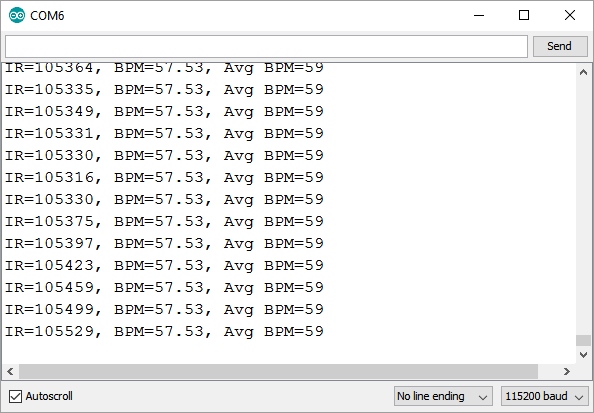
Open the Example5 HeartRate sketch, and load it on your Redboard or Uno.
This example runs a filter called the PBA or Penpheral Beat Amplitude algorithm on the IR data. This algorithm is able to pull out the blips from all the noise and calculate the time between blips to get a heart rate. The output is your instantaneous heart rate and your average heart rate (BPM).
As one might expect the human body isn't as precise as a metronome. The time between pulses can vary quite a bit so this sketch takes a running average of 4 readings to try to smooth out the variance.
Python Package
Note: This tutorial assumes you are using the latest version of Python 3. If this is your first time using Python or I2C hardware on a Raspberry Pi, please checkout our tutorial on Python Programming with the Raspberry Pi and the Raspberry Pi SPI and I2C Tutorial. Jetson Nano users can check out this tutorial on Working with Qwiic on a Jetson Nano through Jupyter Notebooks.
We've written a Python package to easily get setup and take readings from the button controller on the Top pHAT. There are two methods for installing the Python package for the button controller.
- Install the all inclusive SparkFun Qwiic Python package.
- Independently install the SparkFun MAX3010x Python package.
The all inclusive SparkFun Qwiic Python package, is recommended as is also installs the required I2C driver as well.
Note: Don't forget to double check that the hardware I2C connection is enabled on your single board computer.
SparkFun Qwiic Package
This repository is hosted on PyPi as the sparkfun-qwiic package. On systems that support PyPi installation via pip3 (use pip for Python 2) is simple, using the following commands:
For all users (note: the user must have sudo privileges):
language:bash
sudo pip3 install sparkfun-qwiic
For the current user:
language:bash
pip3 install sparkfun-qwiic
Independent Installation
You can install the sparkfun-qwiic-max3010x Python package independently, which is hosted by PyPi. However, if you prefer to manually download and install the package from the GitHub repository, you can grab them here (*Please be aware of any package dependencies. You can also check out the repository documentation page, hosted on ReadtheDocs.):
PyPi Installation
This repository is hosted on PyPi as the sparkfun-qwiic-max3010x package. On systems that support PyPi installation via pip3 (use pip for Python 2) is simple, using the following commands:
For all users (note: the user must have sudo privileges):
language:bash
sudo pip3 install sparkfun-qwiic-max3010x
For the current user:
language:bash
pip3 install sparkfun-qwiic-max3010x
Local Installation
To install, make sure the setuptools package is installed on the system.
Direct installation at the command line (use python for Python 2):
language:bash
python3 setup.py install
To build a package for use with pip3:
language:bash
python3 setup.py sdist
A package file is built and placed in a subdirectory called dist. This package file can be installed using pip3.
language:bash
cd dist
pip3 install sparkfun_qwic_max3010x-<version>.tar.gz
Python Package Operation
Before we jump into getting readings, let's take a closer look at the available functions in the Python package. Below, is a description of the basic functionality of the Python package. This includes the package organization, built-in methods, and their inputs and/or outputs. For more details on how the Python package works, check out the source code and package documentation.
Dependencies
This Python package has a very few dependencies in the code, listed below:
language:python
from __future__ import print_function
import struct
import qwiic_i2c
import time
from smbus2 import SMBus, i2c_msg
_i2c_msg = i2c_msg

from . import heart_rate
hr = heart_rate.HeartRate()
Default Variables
The default variables, in the code, for this Python package are listed below:
language:python
# Some devices have multiple availabel addresses - this is a list of these addresses.
# NOTE: The first address in this list is considered the default I2C address for the
# device.
_AVAILABLE_I2C_ADDRESS = [0x57] # 7-bit I2C Address
# Note that MAX30102 has the same I2C address and Part ID

# Status Registers
MAX30105_INTSTAT1 =     0x00
MAX30105_INTSTAT2 =     0x01
MAX30105_INTENABLE1 =       0x02
MAX30105_INTENABLE2 =       0x03

# FIFO Registers
MAX30105_FIFOWRITEPTR =     0x04
MAX30105_FIFOOVERFLOW =     0x05
MAX30105_FIFOREADPTR =  0x06
MAX30105_FIFODATA =     0x07

# Configuration Registers
MAX30105_FIFOCONFIG =       0x08
MAX30105_MODECONFIG =       0x09
MAX30105_PARTICLECONFIG =   0x0A     # Note, sometimes listed as "SPO2" config in datasheet (pg. 11)
MAX30105_LED1_PULSEAMP =    0x0C
MAX30105_LED2_PULSEAMP =    0x0D
MAX30105_LED3_PULSEAMP =    0x0E
MAX30105_LED_PROX_AMP =     0x10
MAX30105_MULTILEDCONFIG1 = 0x11
MAX30105_MULTILEDCONFIG2 = 0x12

# Die Temperature Registers
MAX30105_DIETEMPINT =       0x1F
MAX30105_DIETEMPFRAC =  0x20
MAX30105_DIETEMPCONFIG =    0x21

# Proximity Function Registers
MAX30105_PROXINTTHRESH =    0x30

# Part ID Registers
MAX30105_REVISIONID =       0xFE
MAX30105_PARTID =           0xFF     # Should always be 0x15. Identical to MAX30102.

# MAX30105 Commands
# Interrupt configuration (pg 13, 14)
MAX30105_INT_A_FULL_MASK =      (~0b10000000)
MAX30105_INT_A_FULL_ENABLE =    0x80
MAX30105_INT_A_FULL_DISABLE =   0x00

MAX30105_INT_DATA_RDY_MASK = (~0b01000000)
MAX30105_INT_DATA_RDY_ENABLE =  0x40
MAX30105_INT_DATA_RDY_DISABLE = 0x00

MAX30105_INT_ALC_OVF_MASK = (~0b00100000)
MAX30105_INT_ALC_OVF_ENABLE =   0x20
MAX30105_INT_ALC_OVF_DISABLE = 0x00

MAX30105_INT_PROX_INT_MASK = (~0b00010000)
MAX30105_INT_PROX_INT_ENABLE = 0x10
MAX30105_INT_PROX_INT_DISABLE = 0x00

MAX30105_INT_DIE_TEMP_RDY_MASK = (~0b00000010)
MAX30105_INT_DIE_TEMP_RDY_ENABLE = 0x02
MAX30105_INT_DIE_TEMP_RDY_DISABLE = 0x00

MAX30105_SAMPLEAVG_MASK =   (~0b11100000)
MAX30105_SAMPLEAVG_1 =  0x00
MAX30105_SAMPLEAVG_2 =  0x20
MAX30105_SAMPLEAVG_4 =  0x40
MAX30105_SAMPLEAVG_8 =  0x60
MAX30105_SAMPLEAVG_16 =     0x80
MAX30105_SAMPLEAVG_32 =     0xA0

MAX30105_ROLLOVER_MASK =    0xEF
MAX30105_ROLLOVER_ENABLE = 0x10
MAX30105_ROLLOVER_DISABLE = 0x00

MAX30105_A_FULL_MASK =  0xF0

# Mode configuration commands (page 19)
MAX30105_SHUTDOWN_MASK =    0x7F
MAX30105_SHUTDOWN =         0x80
MAX30105_WAKEUP =           0x00

MAX30105_RESET_MASK =       0xBF
MAX30105_RESET =            0x40

MAX30105_MODE_MASK =        0xF8
MAX30105_MODE_REDONLY =     0x02
MAX30105_MODE_REDIRONLY =   0x03
MAX30105_MODE_MULTILED =    0x07

# Particle sensing configuration commands (pgs 19-20)
MAX30105_ADCRANGE_MASK =    0x9F
MAX30105_ADCRANGE_2048 =    0x00
MAX30105_ADCRANGE_4096 =    0x20
MAX30105_ADCRANGE_8192 =    0x40
MAX30105_ADCRANGE_16384 =   0x60

MAX30105_SAMPLERATE_MASK = 0xE3
MAX30105_SAMPLERATE_50 =    0x00
MAX30105_SAMPLERATE_100 =   0x04
MAX30105_SAMPLERATE_200 =   0x08
MAX30105_SAMPLERATE_400 =   0x0C
MAX30105_SAMPLERATE_800 =   0x10
MAX30105_SAMPLERATE_1000 = 0x14
MAX30105_SAMPLERATE_1600 = 0x18
MAX30105_SAMPLERATE_3200 = 0x1C

MAX30105_PULSEWIDTH_MASK = 0xFC
MAX30105_PULSEWIDTH_69 =    0x00
MAX30105_PULSEWIDTH_118 =   0x01
MAX30105_PULSEWIDTH_215 =   0x02
MAX30105_PULSEWIDTH_411 =   0x03

#Multi-LED Mode configuration (pg 22)
MAX30105_SLOT1_MASK =       0xF8
MAX30105_SLOT2_MASK =       0x8F
MAX30105_SLOT3_MASK =       0xF8
MAX30105_SLOT4_MASK =       0x8F

SLOT_NONE =                 0x00
SLOT_RED_LED =          0x01
SLOT_IR_LED =               0x02
SLOT_GREEN_LED =            0x03
SLOT_NONE_PILOT =           0x04
SLOT_RED_PILOT =            0x05
SLOT_IR_PILOT =             0x06
SLOT_GREEN_PILOT =      0x07

MAX_30105_EXPECTEDPARTID = 0x15
Class
QwiicMax3010x() or QwiicMax3010x(address)
This Python package operates as a class object, allowing new instances of that type to be made. An __init__() constructor is used that creates a connection to an I2C device over the I2C bus using the default or specified I2C address.
The Constructor
A constructor is a special kind of method used to initialize (assign values to) the data members needed by the object when it is created.
__init__(address=None, i2c_driver=None):
_AVAILABLE_I2C_ADDRESS variable.qwiic_i2c.getI2CDriver(). Users should use the default I2C driver and leave this field blank.Functions
A function is an attribute of the class, which defines a method for instances of that class. In simple terms, they are objects for the operations (or methods) of the class. A list of all the available functions are detailed on the API Reference page of ReadtheDocs for the Qwiic_MAX3010x_Py Python package.
Upgrading the Python Package
In the future, changes to the Python package might be made. Updating the installed packages has to be done individually for each package (i.e. sub-modules and dependencies won't update automatically and must be updated manually). For the sparkfun-qwiic-max3010x Python package, use the following command (use pip for Python 2):
For all users (note: the user must have sudo privileges):
language:bash
sudo pip3 install --upgrade sparkfun-qwiic-max3010x
For the current user:
language:bash
pip3 install --upgrade sparkfun-qwiic-max3010x
Python Examples
☠ Do not rely on our examples for medical diagnosis or any life saving applications
Note: Particle detection, heart rate measurement, and photoplethysmography (for pulse oximetry) are applications of the MAX30101. These applications require a fundamental understanding of the operating principles of the sensor and a conceptual knowledge of the applications. Although, we provide some examples for these applications; they are primarily for demonstration purposes only and are not supported by SparkFun.
Note: Although there is an example, Maxim has since removed the proximity sensing and particle detection as functionalities of this sensor in their datasheet.
There are several examples written for the Qwiic_MAX30101x_Py Python package. They can be found in the Examples folder of the GitHub repository or view on the repository documentation page, hosted on ReadtheDocs. Users can also grab them here, using the link below. (*Please be aware of any package dependencies.):
Example 1 - Basic Readings
Example 1 outputs the raw values read by the sensor.
language:python
#!/usr/bin/env python
#-----------------------------------------------------------------------------
# ex1_Basic_Readings.py
#
# Simple example for the qwiic MAX3010x device
# Outputs all Red/IR/Green values.
#
#------------------------------------------------------------------------
#
# Written by Pete Lewis
# SparkFun Electronics, May 2020
#
# Based on code from the SparkFun MAX3010x Sensor Arduino Library
# https://github.com/sparkfun/SparkFun_MAX3010x_Sensor_Library
# By: Nathan Seidle @ SparkFun Electronics, October 2nd, 2016
#
# This python library supports the SparkFun Electroncis qwiic
# qwiic sensor/board ecosystem on a Raspberry Pi (and compatable) single
# board computers.
#
# More information on qwiic is at https://www.sparkfun.com/qwiic
#
# Do you like this library? Help support SparkFun. Buy a board!
#
#==================================================================================
# Copyright (c) 2019 SparkFun Electronics
#
# Permission is hereby granted, free of charge, to any person obtaining a copy
# of this software and associated documentation files (the "Software"), to deal
# in the Software without restriction, including without limitation the rights
# to use, copy, modify, merge, publish, distribute, sublicense, and/or sell
# copies of the Software, and to permit persons to whom the Software is
# furnished to do so, subject to the following conditions:
#
# The above copyright notice and this permission notice shall be included in all
# copies or substantial portions of the Software.
#
# THE SOFTWARE IS PROVIDED "AS IS", WITHOUT WARRANTY OF ANY KIND, EXPRESS OR
# IMPLIED, INCLUDING BUT NOT LIMITED TO THE WARRANTIES OF MERCHANTABILITY,
# FITNESS FOR A PARTICULAR PURPOSE AND NONINFRINGEMENT. IN NO EVENT SHALL THE
# AUTHORS OR COPYRIGHT HOLDERS BE LIABLE FOR ANY CLAIM, DAMAGES OR OTHER
# LIABILITY, WHETHER IN AN ACTION OF CONTRACT, TORT OR OTHERWISE, ARISING FROM,
# OUT OF OR IN CONNECTION WITH THE SOFTWARE OR THE USE OR OTHER DEALINGS IN THE
# SOFTWARE.
#==================================================================================
# Example 1
#

from __future__ import print_function
import qwiic_max3010x
import time
import sys

def runExample():

    print("\nSparkFun MAX3010x Photodetector - Example 1\n")
    sensor = qwiic_max3010x.QwiicMax3010x()

    if sensor.begin() == False:
        print("The Qwiic MAX3010x device isn't connected to the system. Please check your connection", \
            file=sys.stderr)
        return
    else:
        print("The Qwiic MAX3010x is connected.")

    if sensor.setup() == False:
        print("Device setup failure. Please check your connection", \
            file=sys.stderr)
        return
    else:
        print("Setup complete.")

    while True:
            print(\
             'R[', sensor.getRed() , '] \t'\
                                                             'IR[', sensor.getIR() , '] \t'\
                                                             'G[', sensor.getGreen() , ']'\
            )
            time.sleep(0.1)

if __name__ == '__main__':
    try:
        runExample()
    except (KeyboardInterrupt, SystemExit) as exErr:
        print("\nEnding Example 1")
        sys.exit(0)
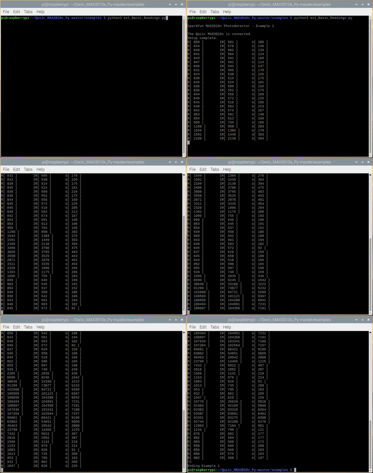
Just as in the Arduino example, feel free to wave you hand over the sensor to see the changes in values. Users should see an output similar to the image below:
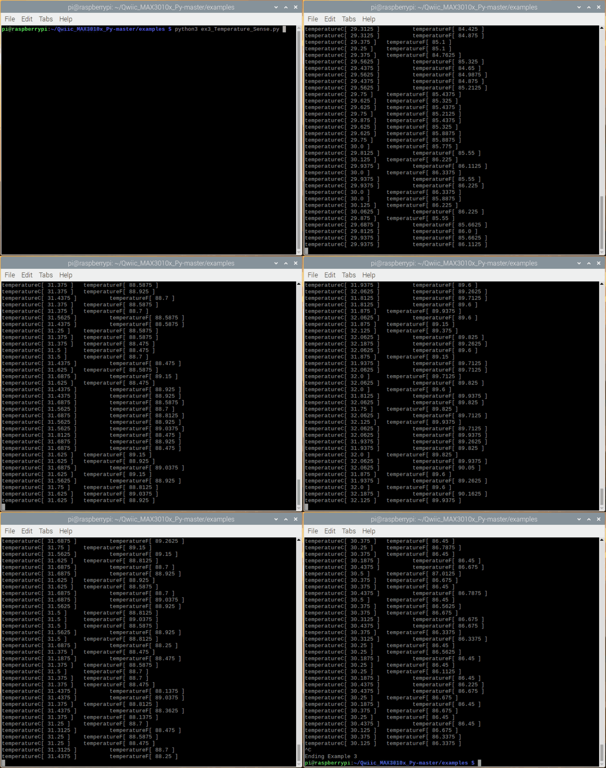
Example 3 - Temperature Sense
Example 3 outputs readings from the on-board temperature sensor in both Celsius and Fahrenheit. The temp sensor is accurate to ±1 °C but has an astonishing precision of 0.0625 °C.
language:python
#!/usr/bin/env python
#-----------------------------------------------------------------------------
# ex3_Temperature_Sesnse.py
#
# Simple example for the qwiic MAX3010x device
# This demo outputs the onboard temperature sensor.
# The temp sensor is accurate to +/-1 C but
# has an astonishing precision of 0.0625 C.
#
#------------------------------------------------------------------------
#
# Written by Pete Lewis
# SparkFun Electronics, May 2020
#
# Based on code from the SparkFun MAX3010x Sensor Arduino Library
# https://github.com/sparkfun/SparkFun_MAX3010x_Sensor_Library
# By: Nathan Seidle @ SparkFun Electronics, October 2016
#
# This python library supports the SparkFun Electroncis qwiic
# qwiic sensor/board ecosystem on a Raspberry Pi (and compatable) single
# board computers.
#
# More information on qwiic is at https://www.sparkfun.com/qwiic
#
# Do you like this library? Help support SparkFun. Buy a board!
#
#==================================================================================
# Copyright (c) 2019 SparkFun Electronics
#
# Permission is hereby granted, free of charge, to any person obtaining a copy
# of this software and associated documentation files (the "Software"), to deal
# in the Software without restriction, including without limitation the rights
# to use, copy, modify, merge, publish, distribute, sublicense, and/or sell
# copies of the Software, and to permit persons to whom the Software is
# furnished to do so, subject to the following conditions:
#
# The above copyright notice and this permission notice shall be included in all
# copies or substantial portions of the Software.
#
# THE SOFTWARE IS PROVIDED "AS IS", WITHOUT WARRANTY OF ANY KIND, EXPRESS OR
# IMPLIED, INCLUDING BUT NOT LIMITED TO THE WARRANTIES OF MERCHANTABILITY,
# FITNESS FOR A PARTICULAR PURPOSE AND NONINFRINGEMENT. IN NO EVENT SHALL THE
# AUTHORS OR COPYRIGHT HOLDERS BE LIABLE FOR ANY CLAIM, DAMAGES OR OTHER
# LIABILITY, WHETHER IN AN ACTION OF CONTRACT, TORT OR OTHERWISE, ARISING FROM,
# OUT OF OR IN CONNECTION WITH THE SOFTWARE OR THE USE OR OTHER DEALINGS IN THE
# SOFTWARE.
#==================================================================================
# Example 3
#

from __future__ import print_function
import qwiic_max3010x
import time
import sys

def runExample():

    print("\nSparkFun MAX3010x Photodetector - Example 3\n")
    sensor = qwiic_max3010x.QwiicMax3010x()

    if sensor.begin() == False:
        print("The Qwiic MAX3010x device isn't connected to the system. Please check your connection", \
            file=sys.stderr)
        return
    else:
        print("The Qwiic MAX3010x is connected.")

    # Setup Sensor
    # The LEDs are very low power and won't affect the temp reading much but
    # we will call setup() with LEDs off, to avoid any local heating (ledMode = 0)

    if sensor.setup(ledMode = 0) == False:
        print("Device setup failure. Please check your connection", \
            file=sys.stderr)
        return
    else:
        print("Setup complete.")

    sensor.enableDIETEMPRDY() # Enable the temp ready interrupt. This is required.

    while True:
            temperature = sensor.readTemperature()
            temperatureF = sensor.readTemperatureF()

            temperature = round(temperature, 4)
            temperatureF = round(temperatureF, 4)

            print(\
             'temperatureC[', temperature , '] \t',\
             'temperatureF[', temperatureF , ']',\
            )


if __name__ == '__main__':
    try:
        runExample()
    except (KeyboardInterrupt, SystemExit) as exErr:
        print("\nEnding Example 3")
        sys.exit(0)
Feel free to heat up the sensor with your finger or blowing on it to cool it down.
Example 4 - Heartbeat Plotter
Note: For this demo, you'll need a rubber band small enough to go through the mounting holes on the breakout. Make sure to follow the example in the Hardware Assembly section for the best results. Additionally, this example requires some software for the plotter to be installed.
On the Raspberry Pi, execute the following lines in the terminal:
sudo apt-get install libatlas3-base libffi-dev at-spi2-core python3-gi-cairosudo pip3 install matplotlib
sudo apt-get install python3-matplotlib
Example 4 is where the fun really begins! Hemoglobin reflects IR light really well, and the MAX30101 is capable of detecting such small changes in IR reflectance that it can detect blood flowing through your finger at different rates.
language:python
#!/usr/bin/env python
#-----------------------------------------------------------------------------
# ex4_HeartBeat_Plotter.py
#
# Simple example for the qwiic MAX3010x device
# Shows the user's heart beat on a graphical plotter
# Using Matplotlib
# To learn more about plotting data in python check out this tutorial:
# https://learn.sparkfun.com/tutorials/graph-sensor-data-with-python-and-matplotlib/
# The example code below was built using the code from the previously mentioned tutorial.
# Thanks Shawn Hymel!
#
# Instructions:
#   1) Install MatplotLib (see below)
#   2) Connect sensor to system via qwiic cable
#   3) Attach sensor to your finger with a rubber band (see below)
#   4) Run this python example
#   5) Checkout the blips!
#   6) Feel the pulse on your neck and watch it mimic the blips
#
#   It is best to attach the sensor to your finger using a rubber band or other tightening
#   device. Humans are generally bad at applying constant pressure to a thing. When you
#   press your finger against the sensor it varies enough to cause the blood in your
#   finger to flow differently which causes the sensor readings to go wonky.
#
# MatplotLib install
# Install Dependencies
# Like any good Linux project, we need to install a number of dependencies and libraries
# in order to get matplotlib to run properly. Make sure you have an Internet connection
# and in a terminal, enter the following commands. You may need to wait several minutes
# while the various packages are downloaded and installed.
#
# sudo apt-get update
# sudo apt-get install libatlas3-base libffi-dev at-spi2-core python3-gi-cairo
# sudo pip3 install cairocffi
# sudo pip3 install matplotlib
#
#------------------------------------------------------------------------
#
# Written by Pete Lewis
# SparkFun Electronics, May 2020
#
# Based on code from the SparkFun MAX3010x Sensor Arduino Library
# https://github.com/sparkfun/SparkFun_MAX3010x_Sensor_Library
# By: Nathan Seidle @ SparkFun Electronics, October 2nd, 2016
#
# This python library supports the SparkFun Electroncis qwiic
# qwiic sensor/board ecosystem on a Raspberry Pi (and compatable) single
# board computers.
#
# More information on qwiic is at https://www.sparkfun.com/qwiic
#
# Do you like this library? Help support SparkFun. Buy a board!
#
#==================================================================================
# Copyright (c) 2019 SparkFun Electronics
#
# Permission is hereby granted, free of charge, to any person obtaining a copy
# of this software and associated documentation files (the "Software"), to deal
# in the Software without restriction, including without limitation the rights
# to use, copy, modify, merge, publish, distribute, sublicense, and/or sell
# copies of the Software, and to permit persons to whom the Software is
# furnished to do so, subject to the following conditions:
#
# The above copyright notice and this permission notice shall be included in all
# copies or substantial portions of the Software.
#
# THE SOFTWARE IS PROVIDED "AS IS", WITHOUT WARRANTY OF ANY KIND, EXPRESS OR
# IMPLIED, INCLUDING BUT NOT LIMITED TO THE WARRANTIES OF MERCHANTABILITY,
# FITNESS FOR A PARTICULAR PURPOSE AND NONINFRINGEMENT. IN NO EVENT SHALL THE
# AUTHORS OR COPYRIGHT HOLDERS BE LIABLE FOR ANY CLAIM, DAMAGES OR OTHER
# LIABILITY, WHETHER IN AN ACTION OF CONTRACT, TORT OR OTHERWISE, ARISING FROM,
# OUT OF OR IN CONNECTION WITH THE SOFTWARE OR THE USE OR OTHER DEALINGS IN THE
# SOFTWARE.
#==================================================================================
# Example 4
#

from __future__ import print_function
import qwiic_max3010x
import time
import sys

sensor = qwiic_max3010x.QwiicMax3010x()

#Plotter Stuff
import matplotlib.pyplot as plt
import matplotlib.animation as animation

# Create figure for plotting
fig = plt.figure()
ax = fig.add_subplot(1, 1, 1)
xlen= 100 #sample number, increments and is used for labeling x axis in plot
xs = list(range(0,xlen))
ys = [0]*xlen
line, = ax.plot(xs, ys)
plt.title('Heartbeat over time')
plt.ylabel('IR Value')

# This function is called periodically from FuncAnimation
def animate(i, ys):
    # Read IR from MAX3010x
    ir = sensor.getIR()

    ys.append(ir)
    ys = ys[-xlen:]
    line.set_ydata(ys)
    ax.set_ylim([min(ys),max(ys)])

    return line,


def runExample():

    print("\nSparkFun MAX3010x Photodetector - Example 4\n")

    if sensor.begin() == False:
        print("The Qwiic MAX3010x device isn't connected to the system. Please check your connection", \
            file=sys.stderr)
        return
    else:
        print("The Qwiic MAX3010x is connected.")

    # Setup to sensor
    ledBrightness = 0x1F # Options: 0=Off to 255=50mA
    sampleAverage = 8 # Options: 1, 2, 4, 8, 16, 32
    ledMode = 3 # Options: 1 = Red only, 2 = Red + IR, 3 = Red + IR + Green
    sampleRate = 100 # Options: 50, 100, 200, 400, 800, 1000, 1600, 3200
    pulseWidth = 411 # Options: 69, 118, 215, 411
    adcRange = 4096 # Options: 2048, 4096, 8192, 16384

    if sensor.setup(ledBrightness, sampleAverage, ledMode, sampleRate, pulseWidth, adcRange) == False:
        print("Device setup failure. Please check your connection", \
            file=sys.stderr)
        return
    else:
        print("Setup complete.")
    # Set up plot to call animate() function periodically
    ani = animation.FuncAnimation(fig, animate, fargs=(ys,), interval=10, blit=True)
    plt.show()


if __name__ == '__main__':
    try:
        runExample()
    except (KeyboardInterrupt, SystemExit) as exErr:
        print("\nEnding Example 4")
        sys.exit(0)
Once the code is running, you should begin to see your pulse as the scale of the axis shrinks into the proper range. Again, the sensor can be a little finicky; especially, if it is moving around slightly. It make take several attempts to view your pulse.
Humans are bad at applying consistent pressure to a thing. Without a rubber band the pressure varies enough to cause the blood in your finger to flow differently which causes the sensor readings to go wonky. It is best to attach the sensor to your finger using a rubber band or other tightening device.
Feel free to compare the plot with your pulse from your carotid artery.
Example 5 - Heartrate
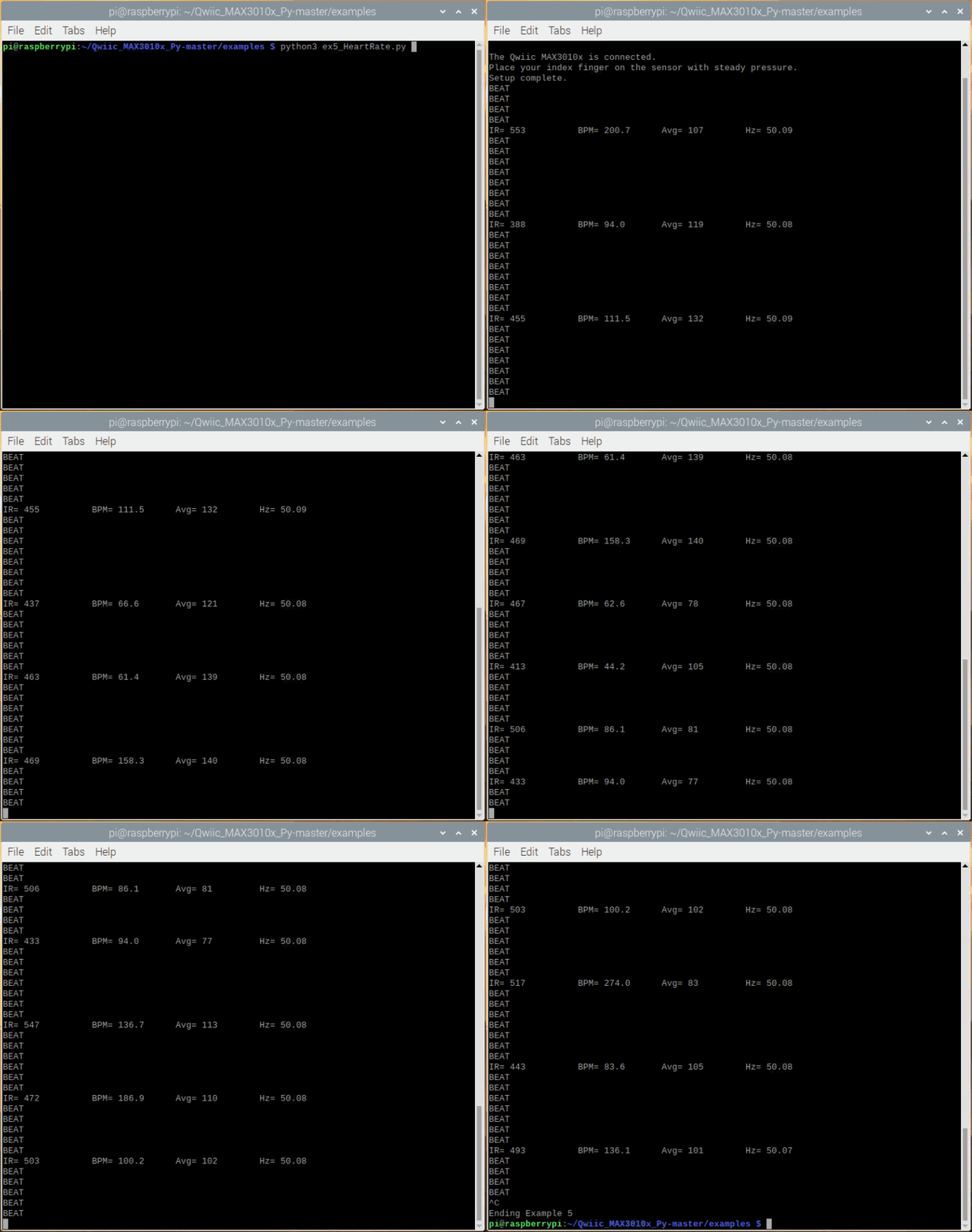
Example 5 runs a filter called the PBA or Penpheral Beat Amplitude algorithm on the IR data. This algorithm is able to pull out the blips from all the noise and calculate the time between blips to get a heart rate. The output is your instantaneous heart rate and your average heart rate (BPM).
language:python
#!/usr/bin/env python
#-----------------------------------------------------------------------------
# ex5_HeartRate.py
#
# Simple example for the qwiic MAX3010x device
# This is a demo to show the reading of heart rate or beats per minute (BPM) using
# a Penpheral Beat Amplitude (PBA) algorithm.
#
# It is best to attach the sensor to your finger using a rubber band or other tightening
# device. Humans are generally bad at applying constant pressure to a thing. When you
# press your finger against the sensor it varies enough to cause the blood in your
# finger to flow differently which causes the sensor readings to go wonky.
#
#------------------------------------------------------------------------
#
# Written by Pete Lewis
# SparkFun Electronics, May 2020
#
# Based on code from the SparkFun MAX3010x Sensor Arduino Library
# https://github.com/sparkfun/SparkFun_MAX3010x_Sensor_Library
# By: Nathan Seidle @ SparkFun Electronics, October 2nd, 2016
#
# This python library supports the SparkFun Electroncis qwiic
# qwiic sensor/board ecosystem on a Raspberry Pi (and compatable) single
# board computers.
#
# More information on qwiic is at https://www.sparkfun.com/qwiic
#
# Do you like this library? Help support SparkFun. Buy a board!
#
#==================================================================================
# Copyright (c) 2019 SparkFun Electronics
#
# Permission is hereby granted, free of charge, to any person obtaining a copy
# of this software and associated documentation files (the "Software"), to deal
# in the Software without restriction, including without limitation the rights
# to use, copy, modify, merge, publish, distribute, sublicense, and/or sell
# copies of the Software, and to permit persons to whom the Software is
# furnished to do so, subject to the following conditions:
#
# The above copyright notice and this permission notice shall be included in all
# copies or substantial portions of the Software.
#
# THE SOFTWARE IS PROVIDED "AS IS", WITHOUT WARRANTY OF ANY KIND, EXPRESS OR
# IMPLIED, INCLUDING BUT NOT LIMITED TO THE WARRANTIES OF MERCHANTABILITY,
# FITNESS FOR A PARTICULAR PURPOSE AND NONINFRINGEMENT. IN NO EVENT SHALL THE
# AUTHORS OR COPYRIGHT HOLDERS BE LIABLE FOR ANY CLAIM, DAMAGES OR OTHER
# LIABILITY, WHETHER IN AN ACTION OF CONTRACT, TORT OR OTHERWISE, ARISING FROM,
# OUT OF OR IN CONNECTION WITH THE SOFTWARE OR THE USE OR OTHER DEALINGS IN THE
# SOFTWARE.
#==================================================================================
# Example 5
#

from __future__ import print_function
import qwiic_max3010x
import time
import sys

def millis():
    return int(round(time.time() * 1000))

def runExample():

    print("\nSparkFun MAX3010x Photodetector - Example 5\n")
    sensor = qwiic_max3010x.QwiicMax3010x()

    if sensor.begin() == False:
        print("The Qwiic MAX3010x device isn't connected to the system. Please check your connection", \
            file=sys.stderr)
        return
    else:
        print("The Qwiic MAX3010x is connected.")

    print("Place your index finger on the sensor with steady pressure.")

    if sensor.setup() == False:
        print("Device setup failure. Please check your connection", \
            file=sys.stderr)
        return
    else:
        print("Setup complete.")

    sensor.setPulseAmplitudeRed(0x0A) # Turn Red LED to low to indicate sensor is running
    sensor.setPulseAmplitudeGreen(0) # Turn off Green LED

    RATE_SIZE = 4 # Increase this for more averaging. 4 is good.
    rates = list(range(RATE_SIZE)) # list of heart rates
    rateSpot = 0
    lastBeat = 0 # Time at which the last beat occurred
    beatsPerMinute = 0.00
    beatAvg = 0
    samplesTaken = 0 # Counter for calculating the Hz or read rate
    startTime = millis() # Used to calculate measurement rate

    while True:

        irValue = sensor.getIR()
        samplesTaken += 1
        if sensor.checkForBeat(irValue) == True:
            # We sensed a beat!
            print('BEAT')
            delta = ( millis() - lastBeat )
            lastBeat = millis()

            beatsPerMinute = 60 / (delta / 1000.0)
            beatsPerMinute = round(beatsPerMinute,1)

            if beatsPerMinute < 255 and beatsPerMinute > 20:
                rateSpot += 1
                rateSpot %= RATE_SIZE # Wrap variable
                rates[rateSpot] = beatsPerMinute # Store this reading in the array

                # Take average of readings
                beatAvg = 0
                for x in range(0, RATE_SIZE):
                    beatAvg += rates[x]
                beatAvg /= RATE_SIZE
                beatAvg = round(beatAvg)

        Hz = round(float(samplesTaken) / ( ( millis() - startTime ) / 1000.0 ) , 2)
        if (samplesTaken % 200 ) == 0:

            print(\
                'IR=', irValue , ' \t',\
                            'BPM=', beatsPerMinute , '\t',\
                                                                                #'DCE', getDCE() , '\t',\
                            'Avg=', beatAvg , '\t',\
                'Hz=', Hz, \
                )

if __name__ == '__main__':
    try:
        runExample()
    except (KeyboardInterrupt, SystemExit) as exErr:
        print("\nEnding Example 5")
        sys.exit(0)
As one might expect the human body isn't as precise as a metronome. The time between pulses can vary quite a bit so this code takes a running average of 4 readings to try to smooth out the variance.
Troubleshooting
Raspberry Pi
For comprehensive information or troubleshooting issues, on the Raspberry Pi, users should check out the Raspberry Pi Foundation website and their forum.
As a general guideline, users should use the following resources when looking for technical information or assistance that is specifically related to the Raspberry Pi itself:
- Raspberry Pi FAQ
- Raspberry Pi Beginner's Subforum
- Raspberry Pi Documentation and Help Guides
- Raspberry Pi Forum
- STICKY - Booting Issues
- See other STICKY topics in the Troubleshooting section of the forum
Nvidia Jetson Nano
For comprehensive information or troubleshooting issues, on the Nvidia Jetson, users should check out the Nvidia website and their forum.
As a general guideline, users should use the following resources when looking for technical information or assistance that is specifically related to the Jetson Nano itself:
- Jetson Support Resources
- Jetson Nano Getting Started Guide
- Developer Kit User Manual
- Jetson Nano Wiki
- Nvidia FAQ
- Jetson Forum
- Jetpack Documentation
For users looking for technical assistance, click on the link. There you will find, basic troubleshooting tips and instructions to get started with posting a topic in our forum. Our technical support team will do their best to assist you.
Resources and Going Further
For more on the SparkFun Photodetector (MAX30101), check out the links below:
- GitHub Hardware Repository -- Home base for the sensor's latest design files
- SparkFun Photodetector (MAX30101) Schematic (PDF)
- SparkFun Photodetector (MAX30101) Eagle Files (ZIP)
- MAX30101 Datasheet (PDF)
- SparkFun MAX3010x Arduino Library -- Source and example files for the Arduino library used in this tutorial.
- Qwiic MAX3010x Python Package
- SFE Product Showcase
Application Notes
Note: Particle detection, heart rate measurement, and photoplethysmography (for pulse oximetry) are applications of the MAX30101. These applications are detailed in the notes below; however, they require an understanding of the operating principles of the sensor and a conceptual knowledge of the application(s). Although, we provided the information below for interested users and may provide some examples of the application in our software; these applications are, unfortunately, not supported by SparkFun and the examples are primarily for demonstration purposes only.
Here are additional resources on how the MAX30101 functions for HR detection and pulse oximetry:
- Basic Concept: The sensor relies on the reflection and scattering of the red and IR light that penetrates into the subcutaneous tissue.
- Penetration Depth Guide For Biosensor Applications
- Guidelines for SpO2 Measurement Using the Maxim® MAX32664 Sensor Hub
- Recommended Configurations and Operating Profilesfor MAX30101/MAX30102 EV Kits
- Multi-wavelength photoplethysmography method for skin arterial pulse extraction
- Signal-to-Noise Ratio as a Quantitative Measure for Optical Biosensors
For more information on particulate matter and their detection, check out these resources:
- Basic Concept: The sensor relies on the reflection and scattering of the red and IR light from particles to detect their presence.
Maxim's Original Firmware for the MAX30102 adapted in our Arduino Library:
For more sensor action, check out these other great SparkFun tutorials.
Vernier Shield Hookup Guide
Photon IMU Shield Hookup Guide
SparkFun WiFi IR Blaster Hookup Guide
Qwiic Micro Magnetometer - MMC5983MA Hookup Guide
Or check out this blog post for ideas:
