SparkFun Photodetector (MAX30101) Hookup Guide
Hardware Overview
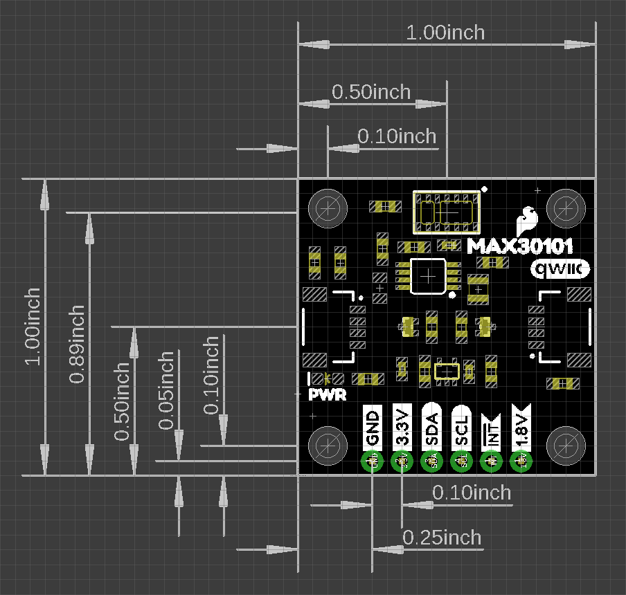
Dimensions
The Qwiic Photodetector Sensor is laid out on the standardized 1" x 1" (2.54 x 2.54 cm) Qwiic breakout board and includes the standard four 0.13" mounting holes, which are compatible with M3 screws.
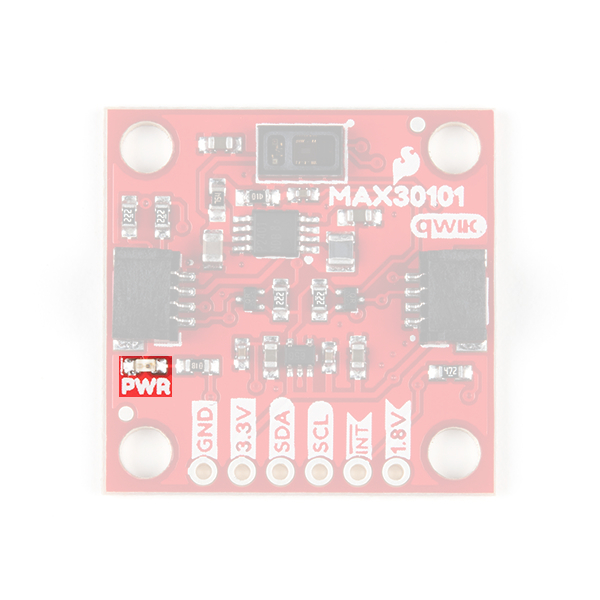
Power LED
There is a power status LED to help make sure that your Qwiic Photodetector Sensor is getting power. You can power the board either through the polarized Qwiic connector system or the breakout pins (3.3V and GND) provided. The Qwiic system is meant to run on 3.3V, be sure that you are NOT using another voltage when using the Qwiic system. A jumper is available on the back of the board to remove power to the LED for low-power applications (see Jumpers section below).
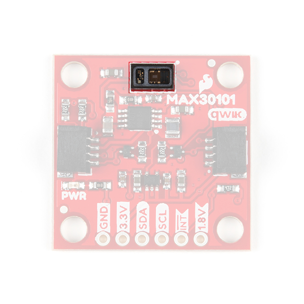
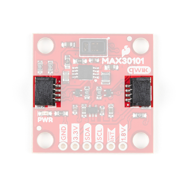
MAX30101
The MAX30101 includes three LEDs and an optical detector in a single package. Behind the window on the left, are red, green, and IR LEDs. While behind the window on the right, is a highly sensitive photon detector.
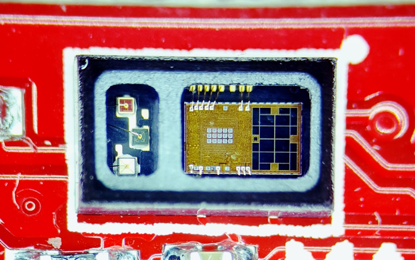
The working principle of the sensor is that the optical detector measures the changes in the reflected light that was emitted from the LEDs. This is great for various application like detecting particles or for photoplethysmography.
(*For more details on the MAX30101, users can check out the datasheet.)
| Characteristic | Description |
|---|---|
| Power |
Supply Voltage: 1.7 - 2.0V Supply Cuurent: 0.6 - 1.1mA LED Driver:
|
| ADC | Resolution: 18-bits (65536 Counts) |
| LEDs |
Wavelength:
Power:
|
| Photodetector | Spectral Range: 640 - 980nm |
| Temperature Sensor |
Range: -40 - 85°C Accuracy: ±1°C |
| I2C Address | 0x57 |
Application Notes
Note: Particle detection, heart rate measurement, and photoplethysmography (for pulse oximetry) are applications of the MAX30101. These applications are detailed in the notes below; however, they require an understanding of the operating principles of the sensor and a conceptual knowledge of the application(s). Although, we provided the information below for interested users and may provide some examples of the application in our software; these applications are, unfortunately, not supported by SparkFun and the examples are primarily for demonstration purposes only.
Here are additional resources on how the MAX30101 functions for HR detection and pulse oximetry:
- Basic Concept: The sensor relies on the reflection and scattering of the red and IR light that penetrates into the subcutaneous tissue.
- Penetration Depth Guide For Biosensor Applications
- Guidelines for SpO2 Measurement Using the Maxim® MAX32664 Sensor Hub
- Recommended Configurations and Operating Profilesfor MAX30101/MAX30102 EV Kits
- Multi-wavelength photoplethysmography method for skin arterial pulse extraction
- Signal-to-Noise Ratio as a Quantitative Measure for Optical Biosensors
For more information on particulate matter and their detection, check out these resources:
- Basic Concept: The sensor relies on the reflection and scattering of the red and IR light from particles to detect their presence.
Maxim's Original Firmware for the MAX30102 adapted in our Arduino Library:
- MAXREFDES117 firmware for Arduino platforms
- Video Demonstration of the MAX30102 using the firmware above (video courtesy of Maxim Integrated.):
Qwiic and I2C
I2C Address
The Qwiic Photodetector Sensor’s I2C address, 0x57, is factory set.
Qwiic Connectors
The simplest way to use the Qwiic Photodetector Sensor is through the Qwiic connect system. The connectors are polarized for the I2C connection and power. (*They are tied to the corresponding power and I2C breakout pins.)
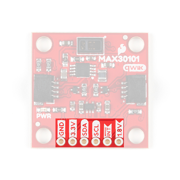
Breakout Pins
The board also provides six labeled breakout pins. You can connect these lines to the I2C bus of your microcontroller and power pins (3.3V and GND), if it doesn't have a Qwiic connector. The interrupt pin is also broken out to use for triggered events.
Interrupt Pin
The interrupt pins (active high) are used to indicate various states of the ADXL313, depending on how they are configured and if they are enabled. The INT pins are pulled down with a 4.7kΩ resistor.
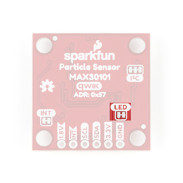
Jumpers
There are three jumpers on the board. Not sure how to cut a jumper? Read here!
Power LED
Cutting the LED jumper will remove the 1kΩ resistors and PWR LED from the 3.3V power. This is useful for low power applications
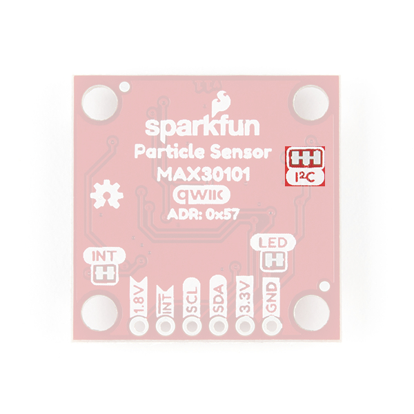
I2C Pull-Up
Cutting the I2C jumper will remove the 2.2kΩ pull-up resistors from the I2C bus. If you have many devices on your I2C bus you may want to remove these jumpers. Be aware that these resistors are also part of the transistor logic level shifting circuit.
Interrupt Pull-up
Cutting the INT jumper will remove the 4.7kΩ pull-up resistors from the interrupt pin.
