SparkFun Inventor's Kit for MicroView
 Joel_E_B
Experiment 9: Spinning a Motor
Introduction
Remember before when you played around with a servo motor? Now we are going to tackle spinning a motor. This requires the use of a transistor, which can switch a larger amount of current than the MicroView can. When using a transistor, you just need to make sure its maximum specs are high enough for your use. The transistor we are using for this circuit is rated at 40V max and 200 milliamps max – perfect for our toy motor! When the motor is spinning and suddenly turned off, the magnetic field inside it collapses, generating a voltage spike. This can damage the transistor. To prevent this, we use a "flyback diode", which diverts the voltage spike around the transistor.
Parts Needed
You will need the following parts:
- 1x 330Ω resistor (Orange Orange Brown Gold)
- 1x Transistor
- 1x Diode
- 1x Motor
- 4x Jumper Wires
Breadboard Setup
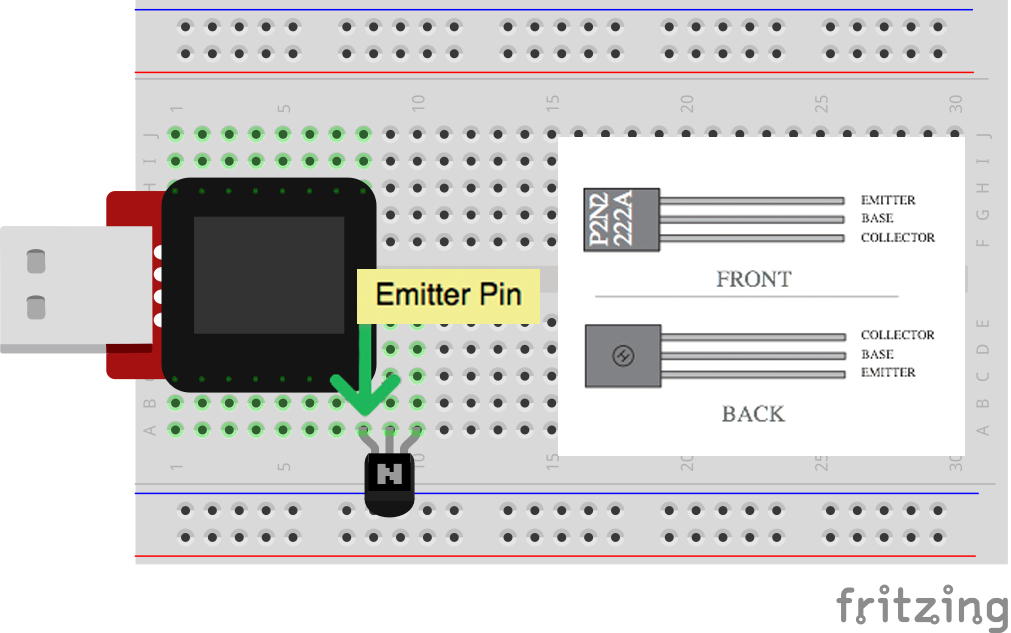
Pay close attention when building this circuit as there are two polarized parts that must be inserted into the breadboard correctly in order for this circuit to work.
The first polarized part is the transistor.
The second is the diode.
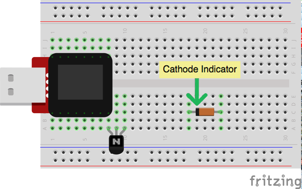
Hook up the rest of your circuit as pictured below:

MicroView Arduino Code
language:c
#include <MicroView.h>      // include MicroView library

int motorPIN = 3;           // set motor control pin
MicroViewWidget *widget;    // declare widget pointer

void setup() {
    uView.begin();          // start MicroView
    uView.clear(PAGE);      // clear page
    pinMode(motorPIN, OUTPUT);      // initialize the digital pin as an output.
    widget = new MicroViewGauge(32,24,90,255,WIDGETSTYLE1);     // set widget as gauge STYLE1
    setPwmFrequency(motorPIN,1);    // set PWM frequency to about 31K
}

void loop() {
    for (int i=90;i<255;i+=10) {    // step i from 90 to 255 by step of 10
        widget->setValue(i);        // set i value to gauge
        uView.display();            // display gauge
        analogWrite(motorPIN, i);   // set the DUTY cycle of the motorPIN
        delay(500);                 // delay 500 ms
    }
}

// function to set the frequency of the PWM pin
// adapted from http://playground.arduino.cc/Code/PwmFrequency
void setPwmFrequency(int pin, int divisor) {
    byte mode;
    if(pin == 5 || pin == 6 || pin == 9 || pin == 10) {
        switch(divisor) {
        case 1: mode = 0x01; break;
        case 8: mode = 0x02; break;
        case 64: mode = 0x03; break;
        case 256: mode = 0x04; break;
        case 1024: mode = 0x05; break;
        default: return;
        }
        if(pin == 5 || pin == 6) {
            TCCR0B = TCCR0B & 0b11111000 | mode;
        } else {
            TCCR1B = TCCR1B & 0b11111000 | mode;
        }
    } else if(pin == 3 || pin == 11) {
        switch(divisor) {
        case 1: mode = 0x01; break;
        case 8: mode = 0x02; break;
        case 32: mode = 0x03; break;
        case 64: mode = 0x04; break;
        case 128: mode = 0x05; break;
        case 256: mode = 0x06; break;
        case 1024: mode = 0x7; break;
        default: return;
        }
        TCCR2B = TCCR2B & 0b11111000 | mode;
    }
}
What You Should See
The DC Motor should spin if you have assembled the circuit’s components correctly, and also verified/uploaded the correct code. If your circuit is not working check the troubleshooting section below.
Code to Note
In this code, we use the command setPwmFrequency(motorPIN,1); to call a function (an encapsulated section of resuable code) for setting the PWM Frequency. Pulse Width Modulation, or PWM, is a technique for getting analog results with digital means. Digital control is used to create a square wave, a signal switched between on and off.
The setPwmFrequency function is defined on line 25.
void setPwmFrequency(int pin, int divisor){
  ...
}
Troubleshooting
USB Port not providing enough power or tripping?
Some USB ports don't provide enough current to spin the motor. If that's the case with a USB port on your computer we recommend powering your MicroView and motor with a powered USB hub or by using batteries. Checkout this circuit for powering your motor with batteries.
Motor Not Spinning
If you sourced your own transistor, double check with the data sheet that the pinout is compatible with a P2N2222AG (many are reversed).
Still No Luck
If you sourced your own motor, double check that it will work with 5 volts and that it does not draw too much power.
Still No Success?
A broken circuit is no fun, send us an e-mail and we will get back to you as soon as we can: TechSupport@sparkfun.com