SparkFun Inventor's Kit for MicroView
 Joel_E_B
Experiment 3: RGB LED
You know what’s even more fun than a blinking LED? Changing colors with one LED. RGB, or red-green-blue, LEDs have three different color-emitting diodes that can be combined to create all sorts of colors. In this circuit, you’ll learn how to use an RGB LED to create unique color combinations. Depending on how bright each diode is, nearly any color is possible!
Parts Needed
You will need the following parts:
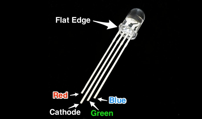
- 1x RGB LED
- 3x 330Ω Resistor (Orange, Orange, Brown, Gold)
- 4x Jumper Wire
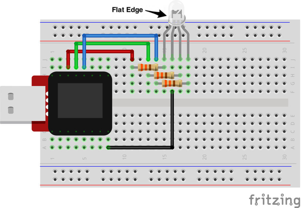
Breadboard Setup
Be sure to pay close attention to the polarity of the RGB LED.
Hook up your circuit as pictured below:
MicroView Arduino Code
language:c
#include <MicroView.h>      // include MicroView library

MicroViewWidget *redWidget, *greenWidget, *blueWidget;  // declare 3 widget pointers

int RED = 6;            // declare RED LED pin 6
int GREEN = 5;          // declare GREEN LED pin 5
int BLUE = 3;           // declare BLUE LED pin 3
int fadeStep = 10;      // declare fading steps
int dly=20;             // declare delay

void setup()
{
    uView.begin();                                  // start MicroView
    uView.clear(PAGE);                              // clear page
    redWidget = new MicroViewSlider(0,0,0,255);     // declare RED widget as slider
    greenWidget = new MicroViewSlider(0,10,0,255);  // declare GREEN widget as slider
    blueWidget = new MicroViewSlider(0,20,0,255);   // declare BLUE widget as slider

    pinMode(RED, OUTPUT);                           // set RED LED pin as OUTPUT
    pinMode(GREEN, OUTPUT);                         // set GREEN LED pin as OUTPUT
    pinMode(BLUE, OUTPUT);                          // set BLUE LED pin as OUTPUT
}

void loop()
{
    int i;                                  // init i variable for general use

    // brightening
    for (i=0;i<=255;i+=fadeStep) {          // step i from 0 to 255 by fadeSteps
        redWidget->setValue(i);             // set brightness value for RED LED to widget
        uView.display();                    // display the content of the screen buffer
        analogWrite(RED,i);                 // set brightness value for RED LED to the pin
        delay(dly);
    }

    // dimming
    for (i=255;i>=0;i-=fadeStep) {          // step i from 255 to 0 by fadeSteps
        redWidget->setValue(i);
        uView.display();
        analogWrite(RED,i);
        delay(dly);
    }

    // brightening
    for (i=0;i<=255;i+=fadeStep) {
        greenWidget->setValue(i);
        uView.display();
        analogWrite(GREEN,i);
        delay(dly);
    }

    // dimming
    for (i=255;i>=0;i-=fadeStep) {
        greenWidget->setValue(i);
        uView.display();
        analogWrite(GREEN,i);
        delay(dly);
    }

    // brightening
    for (i=0;i<256;i+=fadeStep) {
        blueWidget->setValue(i);
        uView.display();
        analogWrite(BLUE,i);
        delay(dly);
    }

    // dimming
    for (i=255;i>=0;i-=fadeStep) {
        blueWidget->setValue(i);
        uView.display();
        analogWrite(BLUE,i);
        delay(dly);
    }
}
What You Should See
You should see your RGB LED go through a colorful sequence of various colors with the slider widget showing the value of each color channel's brightness.
Code to Note
A for() loop is used to step a number across a range, and repeatedly runs code within the brackets {} until a condition is met. We use for loops to change over time the intensity of our RGB pin's brightness. The variable "i" starts a 0, ends at 255, and increases by the amount of the variable fadeStep.
for (i=0;i<=255;i+=fadeStep)
{}
The MicroView is very very fast, capable of running thousands of lines of code each second. To slow it down so that we can see what it's doing, we'll often insert delays into the code. delay() counts in milliseconds; there are 1000 ms in one second.
delay(dly);
Troubleshooting
LED Remains Dark or Shows Incorrect Color
With the four pins of the LED so close together, it’s sometimes easy to misplace one. Double check each pin is where it should be.
Seeing Red
The red diode within the RGB LED may be a bit brighter than the other two. To make your colors more balanced, use a higher Ohm resistor. Or adjust in code. Change
analogWrite(RED,i);
to
analogWrite(RED,i/3);
Still No Success?
A broken circuit is no fun, send us an e-mail and we will get back to you as soon as we can: TechSupport@sparkfun.com
Pulse-Width Modulation
We've seen that the Arduino can read analog voltages (voltages between 0 and 5 volts) using the analogRead() function. Is there a way for the MicroView to output analog voltages as well?
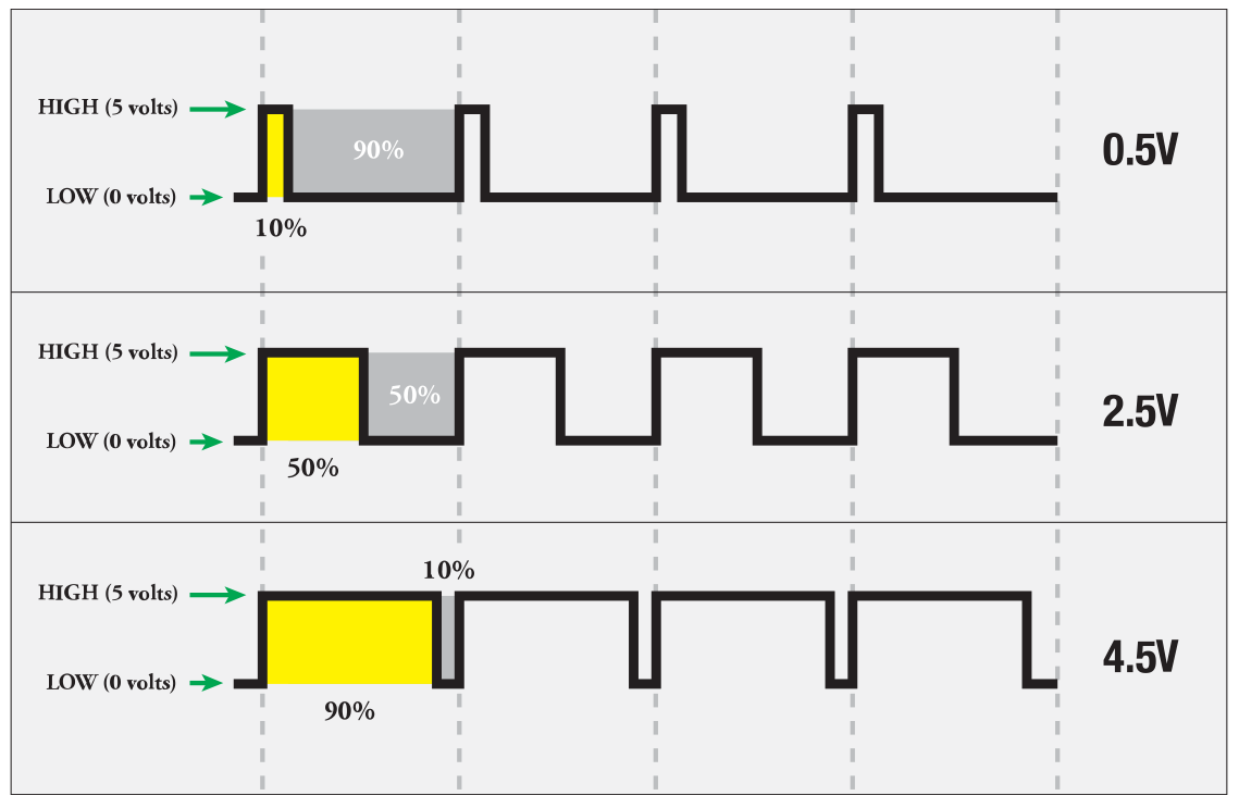
The answer is no... and yes. The MicroView does not have a true analog voltage output. But, because the MicroView is so fast, it can fake it using something called PWM ("Pulse-Width Modulation").
Pins named 3, 5, and 6 within the Arduino code, map to the MicoView physical pins of 12, 13, and 14. Each of these pins are PWM/analogWrite out compatible.
PWM varies the amount of time that a blinking pin spends HIGH vs. the time it spends LOW. If the pin spends most of its time HIGH, a LED connected to that pin will appear bright. If it spends most of its time LOW, the LED will look dim. Because the pin is blinking much faster than your eye can detect, the MicroView creates the illusion of a "true" analog output.