SparkFun Inventor's Kit for MicroView
 Joel_E_B
Introduction
Welcome to the Experiment Guide for the SparkFun Inventor's Kit for MicroView, or the SIK for MicroView for short. This tutorial will guide you through eleven experiments to help you better understand your MicroView, and, once finished, you should have the knowledge necessary to make your MicroView project dreams a reality.
SparkFun Inventor's Kit for MicroView
KIT-13205Included Materials
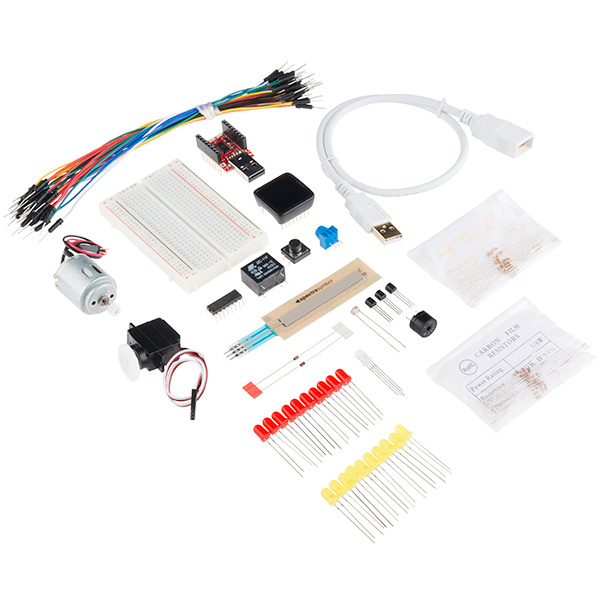
Before you do anything, you should make sure that you have all the necessary parts included with the SIK for MicroView. It's a good idea to familiarize yourself with the parts now, so you know what to look for when it comes time to build the circuits.
- SparkFun MicroView - OLED Arduino Module
- SparkFun MicroView - USB Programmer
- USB Cable Extension - 1.5 Foot
- White Solderless Breadboard
- 74HC595 Shift Register
- 2N2222 Transistors
- 1N4148 Diodes
- DC Motor with Gear
- Small Servo
- SPDT 5V Relay
- TMP36 Temp Sensor
- Softpot
- Jumper Wires
- Photocell
- RGB LED
- Red & Yellow LEDs
- 10K Trimpot
- Piezo Speaker
- Big 12mm Button
- 330Ohm and 10KOhm Resistors
Suggested Reading
To make your MicroView experience as enjoyable as possible, we recommend you be familiar with the following concepts before beginning.
MicroView Overview
Let’s first familiarize ourselves with the MicroView and its pins. Below you'll find a list of specifications as well as a graphical datasheet detailing the function(s) of each pin.
Hardware Specifications
- Input Voltage : 3.3VDC - 16VDC
- Display : 64x48 OLED Display
- Microcontroller : ATmega328P
- Operating Voltage : 5V
- Digital I/O Pins : 12 (of which 3 provide PWM output)
- Analog Input Pins : 6
- Flash Memory : 32 KB
- SRAM : 2 KB
- EEPROM : 1 Kilobyte
- Clock Speed : 16 Mhz
Pin Configuration
The MicroView has 16 "physical pins" that map to corresponding "Arduino pins" that can be referenced from within your Arduino sketch. For example, Physical Pin2 maps to the Arduino's pin A5 (analog pin 5).
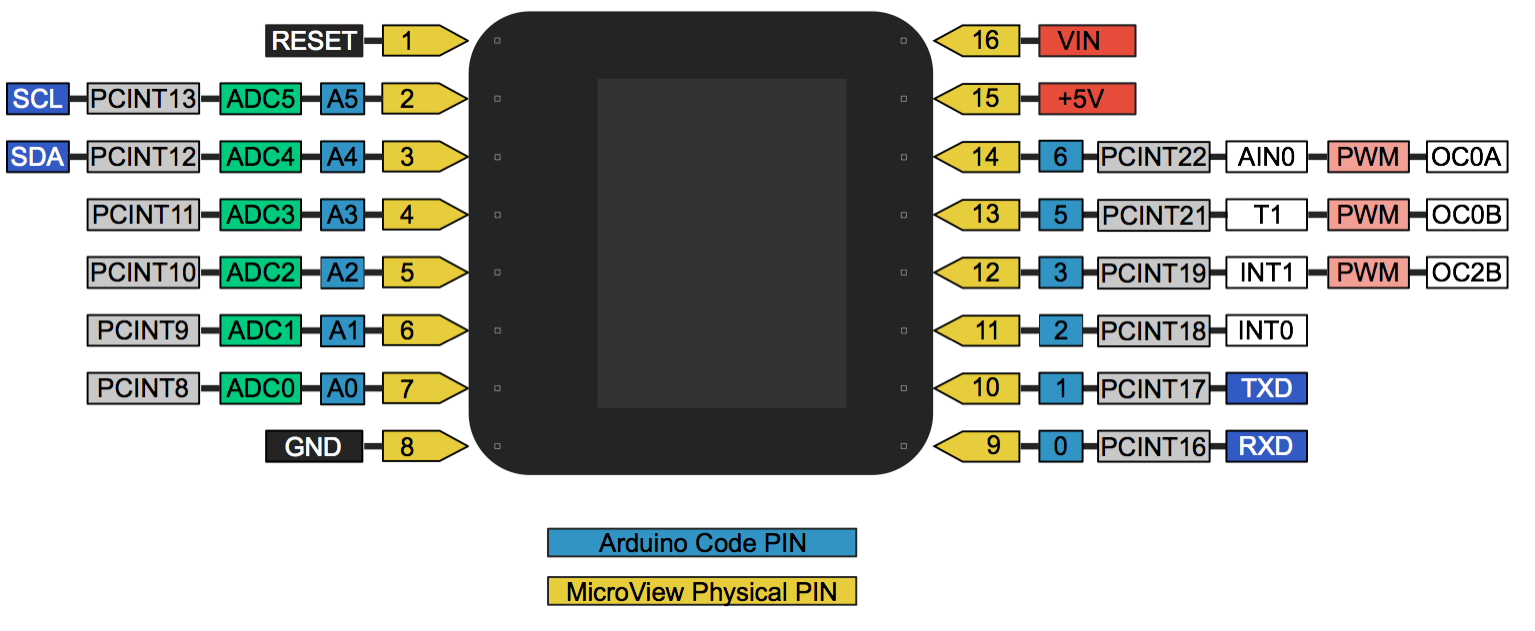
The pin numbering for the MicroView increments as you move counter-clockwise.
The MicroView's physical Pin1 is denoted by a dot on the underside of the MicroView.
For more details on each pin's function, please refer to the ATmega328P Datasheet.
Quick Start Experiment
The MicroView comes with preinstalled code to get you learning right out of the box without having to do any programming. Using just a few components, you can learn the in's and out's of the MicroView.
Setting Up Your MicroView
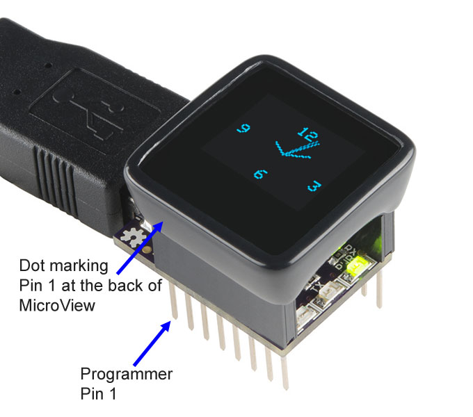
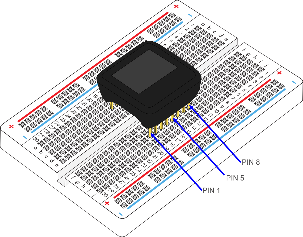
Identify PIN 1 of MicroView based on the following diagram, or refer back to the MicroView Overview section.
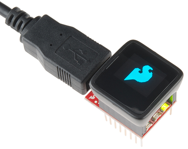
MicroView with USB Programmer
The quickest way to get started is to use the USB programmer.
Insert the MicroView to the USB Programmer, then connect the female end of the USB extension cable to the factory USB Programmer.
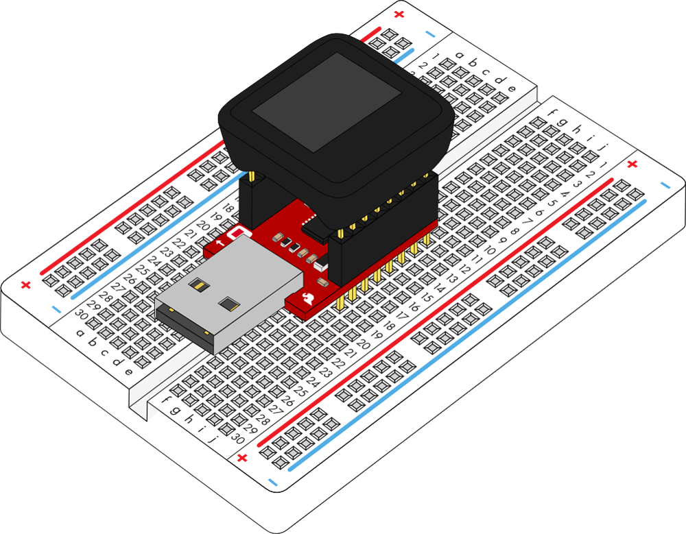
Connect the male end of the USB extension cable to the computer. The MicroView will power on, and the demo will start.
MicroView without USB Programmer
If you would like to use the MicroView without the USB Programmer, you will need the following (please note that the 9V battery and snap connector will need to be purchased separately):
- 9V Battery
- 9V Snap Connector (Remove the Molex connector, replace both wires with male header pins if necessary)
Connect the required parts based on the diagram below. Plug in the battery connectors last. Once plugged in, the 9V battery will power the MicroView through the VIN pin (PIN 1).
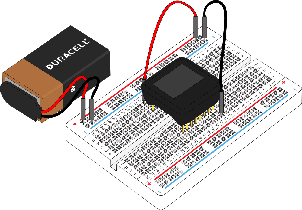
As soon as the MicroView is powered, the demo will start.
Learn How to Use MicroView
The MicroView comes pre-programmed with a few simple built-in tutorials to help you get use to inserting jumper wires, resistors and an LED. Skip these tutorials if you are already familiar with them. They will begin after the visual demo.
Simple Tutorial 1
Follow the instruction displayed on the MicroView, and connect PIN 5 and PIN 8 of the MicroView with a jumper using the following diagram as reference:

Once you have successfully connected PIN 5 and PIN 8 of the MicroView, a “Well done!” message will be displayed. To proceed to the next simple tutorial, remove the jumper.
Simple Tutorial 2
Follow the instruction displayed on the MicroView, and connect PIN 3 and PIN 8 of the MicroView with a jumper using the following diagram as reference:

Once you have successfully connected PIN 3 and PIN 8 of the MicroView, a “Well done!” message will be displayed. To proceed to the next simple tutorial, remove the jumper.
Simple Tutorial 3
Follow the instruction displayed on the MicroView, and connect PIN 2 and PIN 8 of the MicroView with a jumper using the following diagram as reference:

Once you have successfully connected PIN 2 and PIN 8 of the MicroView, a “Well done!” message will be displayed. To proceed to the next simple tutorial, remove the jumper.
Simple Tutorial 4
Follow the instruction displayed on the MicroView, and connect PIN 4 and PIN 8 of the MicroView with a 330Ω resistor using the following diagram as reference:

Once you have successfully connected PIN 4 and PIN 8 of the MicroView with the resistor, a “Well done!” message will be displayed. To proceed to the next simple tutorial, remove the resistor.
Simple Tutorial 5
Follow the instruction displayed on the MicroView, and connect PIN 4 and PIN 8 of the MicroView with a 10KΩ resistor using the following diagram as reference:

Once you have successfully connected PIN 4 and PIN 8 of the MicroView with the resistor, a “Well done!” message will be displayed. To proceed to the next simple tutorial, remove the resistor.
Simple Tutorial 6
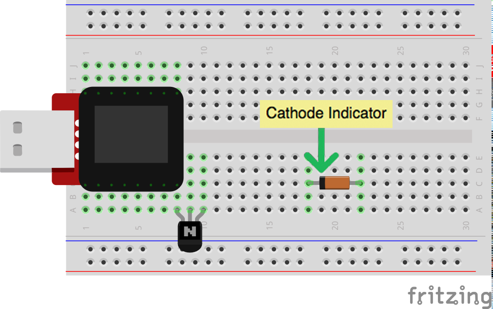
Follow the instruction displayed on the MicroView, connect PIN 5 and PIN 8 of the MicroView with a 330Ω resistor using the following diagram as reference:

With the resistor still at the same place, insert an LED with both of the pins at PIN 4 and PIN 5 of MicroView respectively using the following diagram as reference.
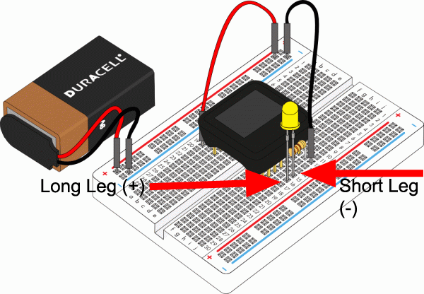
The MicroView is able to detect if the LED is inserted with the correct polarity, and it will begin blinking the LED.
If the LED does not blink, remove the LED and turn the pins the other way round and connect them to PIN 4 and PIN 5 of the MicroView.
With that, you are now ready to upload code and begin building the experiments in this guide.
If you would like to load the Demo Sketch back on to the MicroView after you have uploaded any other code, you can find the MicroViewDemo.ino sketch in the MicroView Library Examples.
Programming the MicroView
The following section will cover all the of the instructions to install the MicroView library and get started using the MicroView with the Arduino IDE.
In order to get your MicroView up and running, there a few easy steps you will need to follow:
- Download the FTDI Drivers
- Install Arduino software and MicroView Library
- Select the right board
- Run your first sketch
Driver Installation
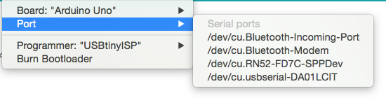
If have never used an Arduino or Arduino compatible device on your computer before, you'll likely need to install the drivers for the FTDI chip located on the MicroView USB Programmer board. If you have never installed an FTDI Driver before, please visit our FTDI Driver Installation tutorial. Once successfully installed, your MicroView should show up as a valid COM Port in the Arduino IDE under Tools -> Ports.
On a Mac or Linux machine, it will appear as /dev/cu.usbmodemXXXXXX or as /dev/cu.usbserialXXXXXX, where the X’s are some specific characters and numbers.
On Windows, it will appear as COMXX, where the X’s are a specific number.
Once you have finished the FTDI driver installation, you will need to prepare your MicroView to be inserted into the computer’s USB port.
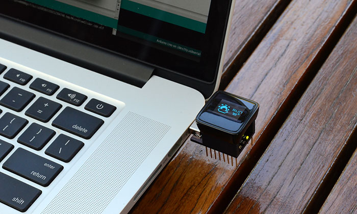
If you're using the USB Programmer, insert the MicroView into the USB Programmer now. Be sure to align Pin 1 of the MicroView with Pin 1 of the USB Programmer. Once you have inserted the MicroView into the USB Programmer, you can now insert the USB Programmer into the USB port of the computer as pictured below. If your computer does not have a right-sided USB port, please use a USB Cable Extension to extend the USB port to the front so that you can easily work with the MicroView.
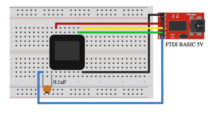
As an alternative to the USB Programmer, you can use a 5V FTDI Basic Breakout or 5V FTDI Cable instead. Connect the FTDI Basic Breakout board as below, and you are ready to go.
Install Arduino IDE and the MicroView Library
If you have not installed the Arduino IDE already, now is the time to do so. Visit our Installing the Arduino IDE tutorial for detailed instructions.
Download the library using the Arduino Library Manager (found in all version of the Arduino IDE from v1.6.4 and on).
Click Sketch -> Include Library -> Manger Libraries to open the Library Manger. Once open, type 'microview' in the search field. Install the SparkFun MicroView library by clicking on the library then clicking the install button. Once installed, there should be a blue 'installed' indicator next to the library.

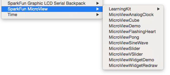
You should now be able to find all the MicroView examples in your Arduino IDE skecthbook.

Board Selection
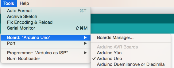
Once the Arduino IDE is up and running, you'll need to select the correct Board. Luckily, the MicroView is supported as an Arduino Uno variant, meaning no extra .brd files need to be installed to use the MicroView. Select Arduino Uno under Tools -> Boards.
In the Arduino IDE under Tools -> Ports, select the correct COM port. This is the port that was found in the Driver Installation section.
For advance user that like to see MicroView as a board by itself in the IDE, add the following board definition to the boards.txt file. Depending on your setup, the boards.txt file usually located at arduino-version\hardware\arduino folder. Replace arduino-version with the right folder name for your Arduino version installed in your computer.
uview.upload.tool=avrdude
uview.bootloader.tool=avrdude
uview.name=MicroView
uview.upload.protocol=arduino
uview.upload.maximum_size=32256
uview.upload.speed=115200
uview.bootloader.low_fuses=0xff
uview.bootloader.high_fuses=0xde
uview.bootloader.extended_fuses=0x05
uview.bootloader.path=optiboot
uview.bootloader.file=optiboot_atmega328.hex
uview.bootloader.unlock_bits=0x3F
uview.bootloader.lock_bits=0x0F
uview.build.mcu=atmega328p
uview.build.f_cpu=16000000L
uview.build.core=arduino
uview.build.variant=standard
With the drivers and library installed and the correct settings in selected in the Arduino IDE, it's time to run our first program on the MicroView. The Hello World sketch in the next section will be the first code we upload to the MicroView.
Experiment 1: Blinking an LED
LEDs (light-emitting diodes) are small, powerful lights that are used in many different applications. To start off the MicroView course, we will work on blinking an LED. That's right -- it's as simple as turning a light on and off. It might not seem like much, but establishing this important baseline will give you a solid foundation as we work toward more complex experiments. Blink is the "Hello World" of hardware.
Parts Needed
You will need the following parts:
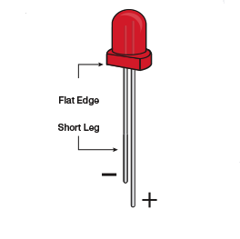
- 1x LED
- 1x 330Ω Resistor (Orange, Orange, Brown, Gold)
Breadboard Setup
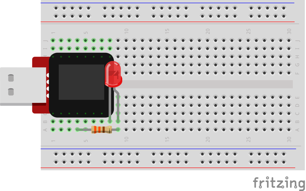
Pay close attention to the polarity of the LED.
Hook up your circuit as pictured below:
MicroView Arduino Code
Upload the following code to your MicroView:
language:c
int LED = A3;               // declare LED as pin A3 of MicroView

void setup()
{
    pinMode(LED, OUTPUT);   // set LED pin as OUTPUT
}

void loop()
{
    digitalWrite(LED, HIGH);    // set LED pin HIGH voltage, LED will be on
    delay(1000);                // delay 1000 ms
    digitalWrite(LED, LOW);     // set LED pin LOW voltage, LED will be off
    delay(1000);                // delay 1000 ms
}
What You Should See
You should see your LED blink on and off. If it isn't, make sure you have assembled the circuit correctly and verified and uploaded the code to your MicroView or see the troubleshooting tips below.
Code to Note
Before you can use one of the MicroView's pins, you need to tell the MicroView whether it is an INPUT or OUTPUT. We use a built-in "function" called pinMode() to do this.
pinMode(A3, OUTPUT);
When you're using a pin as an OUTPUT, you can command it to be HIGH (output 5 volts), or LOW (output 0 volts).
digitalWrite(A3, HIGH);
Arduino programs run in a loop. When the MicroView sees the delay() command, it will pause the loop for the amount of time (in milliseconds). For example delay(1000) will stop the loop for one second as there are 1000 ms in one second.
delay(1000);
Troubleshooting
LED Not Lighting Up?
LEDs will only work in one direction. Try taking it out and turning it around 180 degrees (no need to worry, installing it backward does no permanent harm).
Still No Success?
A broken circuit is no fun, send us an e-mail and we will get back to you as soon as we can: TechSupport@sparkfun.com
Experiment 2: Reading a Potentiometer
In this circuit, you’ll work with a potentiometer. A potentiometer is also known as a variable resistor. When it’s connected with 5 volts across its two outer pins, the middle pin outputs a voltage between 0 and 5, depending on the position of the knob on the potentiometer. A potentiometer is a perfect demonstration of a variable voltage divider circuit. The voltage is divided proportionate to the resistance between the middle pin and the ground pin. In this circuit, you’ll learn how to use a potentiometer and display its value on the MicroView.
Parts Needed
You will need the following parts:
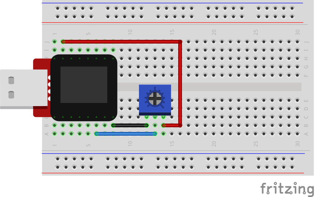
- 1x Potentiometer
- 3x Jumper Wire
Breadboard Setup
Hook up your circuit as pictured below:
MicroView Arduino Code
Upload the following code to your MicroView:
language:c
#include <MicroView.h>          // include MicroView library

MicroViewWidget *widget;        // create widget pointer
MicroViewWidget *widget2;       // create widget pointer

int sensorPin = A1;    // select the input pin for the potentiometer
int sensorValue = 0;  // variable to store the value coming from the sensor

void setup()
{
    digitalWrite(sensorPin, HIGH);      // Internal Pull-up
    pinMode(sensorPin, INPUT);          // make pin as INPUT
    uView.begin();                      // start MicroView
    uView.clear(PAGE);                  // clear page
    widget = new MicroViewSlider(0, 0, 0, 1024);    // make widget as Slider
    widget2 = new MicroViewSlider(0, 20, 0, 1024, WIDGETSTYLE1);    // make widget as Silder STYLE1
    uView.display();                    // display the content in the screen buffer
}

void loop()
{
    sensorValue = analogRead(sensorPin);    // read sensorPin
    widget->setValue(sensorValue);          // set value of sensorPin to widget
    widget2->setValue(sensorValue);         // set value of sensorPin to widget
    uView.display();                        // display the content in the screen buffer
}
What You Should See
By turning the potentiometer's knob you should see on your MicroView's display two different styles of widget reflect the reading of the potentiometer.
Code to Note
A “variable” is a stored value you’ve given a name to. You must introduce, or "declare" variables before you use them; here we're declaring a variable called sensorValue, of type "int" (integer). Don't forget that variable names are case-sensitive!
int sensorValue;
We use the analogRead() function to read the value on an analog pin. analogRead() takes one parameter, the analog pin you want to use ("sensorPin"), and returns a number ("sensorValue") between 0 (0 volts) and 1023 (5 volts).
sensorValue = analogRead(sensorPin);
Troubleshooting
LED Not Lighting Up?
LEDs will only work in one direction. Try taking it out and turning it around 180 degrees (no need to worry, installing it backward does no permanent harm).
Still No Success?
A broken circuit is no fun, send us an e-mail and we will get back to you as soon as we can: TechSupport@sparkfun.com
Experiment 3: RGB LED
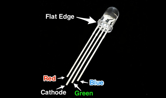
You know what’s even more fun than a blinking LED? Changing colors with one LED. RGB, or red-green-blue, LEDs have three different color-emitting diodes that can be combined to create all sorts of colors. In this circuit, you’ll learn how to use an RGB LED to create unique color combinations. Depending on how bright each diode is, nearly any color is possible!
Parts Needed
You will need the following parts:
- 1x RGB LED
- 3x 330Ω Resistor (Orange, Orange, Brown, Gold)
- 4x Jumper Wire
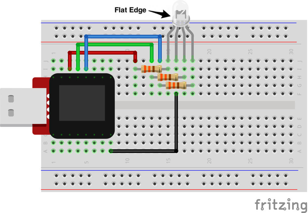
Breadboard Setup
Be sure to pay close attention to the polarity of the RGB LED.
Hook up your circuit as pictured below:
MicroView Arduino Code
language:c
#include <MicroView.h>      // include MicroView library

MicroViewWidget *redWidget, *greenWidget, *blueWidget;  // declare 3 widget pointers

int RED = 6;            // declare RED LED pin 6
int GREEN = 5;          // declare GREEN LED pin 5
int BLUE = 3;           // declare BLUE LED pin 3
int fadeStep = 10;      // declare fading steps
int dly=20;             // declare delay

void setup()
{
    uView.begin();                                  // start MicroView
    uView.clear(PAGE);                              // clear page
    redWidget = new MicroViewSlider(0,0,0,255);     // declare RED widget as slider
    greenWidget = new MicroViewSlider(0,10,0,255);  // declare GREEN widget as slider
    blueWidget = new MicroViewSlider(0,20,0,255);   // declare BLUE widget as slider

    pinMode(RED, OUTPUT);                           // set RED LED pin as OUTPUT
    pinMode(GREEN, OUTPUT);                         // set GREEN LED pin as OUTPUT
    pinMode(BLUE, OUTPUT);                          // set BLUE LED pin as OUTPUT
}

void loop()
{
    int i;                                  // init i variable for general use

    // brightening
    for (i=0;i<=255;i+=fadeStep) {          // step i from 0 to 255 by fadeSteps
        redWidget->setValue(i);             // set brightness value for RED LED to widget
        uView.display();                    // display the content of the screen buffer
        analogWrite(RED,i);                 // set brightness value for RED LED to the pin
        delay(dly);
    }

    // dimming
    for (i=255;i>=0;i-=fadeStep) {          // step i from 255 to 0 by fadeSteps
        redWidget->setValue(i);
        uView.display();
        analogWrite(RED,i);
        delay(dly);
    }

    // brightening
    for (i=0;i<=255;i+=fadeStep) {
        greenWidget->setValue(i);
        uView.display();
        analogWrite(GREEN,i);
        delay(dly);
    }

    // dimming
    for (i=255;i>=0;i-=fadeStep) {
        greenWidget->setValue(i);
        uView.display();
        analogWrite(GREEN,i);
        delay(dly);
    }

    // brightening
    for (i=0;i<256;i+=fadeStep) {
        blueWidget->setValue(i);
        uView.display();
        analogWrite(BLUE,i);
        delay(dly);
    }

    // dimming
    for (i=255;i>=0;i-=fadeStep) {
        blueWidget->setValue(i);
        uView.display();
        analogWrite(BLUE,i);
        delay(dly);
    }
}
What You Should See
You should see your RGB LED go through a colorful sequence of various colors with the slider widget showing the value of each color channel's brightness.
Code to Note
A for() loop is used to step a number across a range, and repeatedly runs code within the brackets {} until a condition is met. We use for loops to change over time the intensity of our RGB pin's brightness. The variable "i" starts a 0, ends at 255, and increases by the amount of the variable fadeStep.
for (i=0;i<=255;i+=fadeStep)
{}
The MicroView is very very fast, capable of running thousands of lines of code each second. To slow it down so that we can see what it's doing, we'll often insert delays into the code. delay() counts in milliseconds; there are 1000 ms in one second.
delay(dly);
Troubleshooting
LED Remains Dark or Shows Incorrect Color
With the four pins of the LED so close together, it’s sometimes easy to misplace one. Double check each pin is where it should be.
Seeing Red
The red diode within the RGB LED may be a bit brighter than the other two. To make your colors more balanced, use a higher Ohm resistor. Or adjust in code. Change
analogWrite(RED,i);
to
analogWrite(RED,i/3);
Still No Success?
A broken circuit is no fun, send us an e-mail and we will get back to you as soon as we can: TechSupport@sparkfun.com
Pulse-Width Modulation
We've seen that the Arduino can read analog voltages (voltages between 0 and 5 volts) using the analogRead() function. Is there a way for the MicroView to output analog voltages as well?
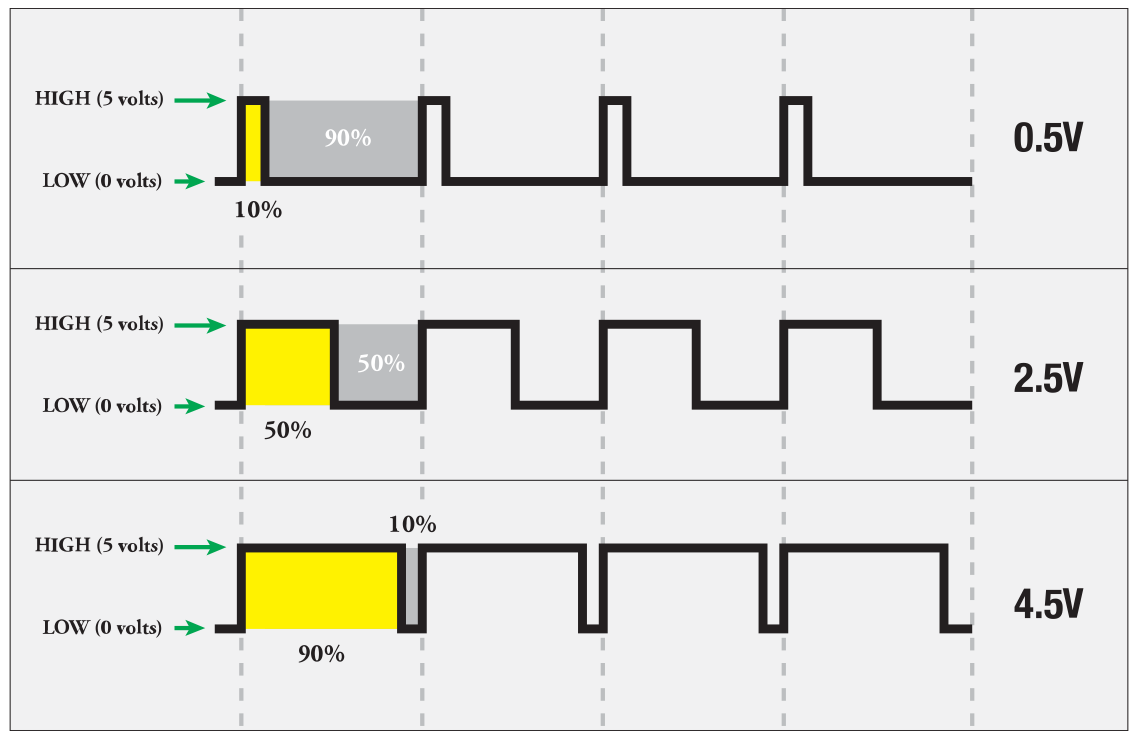
The answer is no... and yes. The MicroView does not have a true analog voltage output. But, because the MicroView is so fast, it can fake it using something called PWM ("Pulse-Width Modulation").
Pins named 3, 5, and 6 within the Arduino code, map to the MicoView physical pins of 12, 13, and 14. Each of these pins are PWM/analogWrite out compatible.
PWM varies the amount of time that a blinking pin spends HIGH vs. the time it spends LOW. If the pin spends most of its time HIGH, a LED connected to that pin will appear bright. If it spends most of its time LOW, the LED will look dim. Because the pin is blinking much faster than your eye can detect, the MicroView creates the illusion of a "true" analog output.
Experiment 4: Push Buttons
In this circuit, we’ll be looking at one of the most common and simple inputs – a push button. The way a push button works with this MicroView tutorial is that when the button is pushed, the contacts in the button connects to the ground, MicroView reads this and reacts accordingly.
Parts Needed
You will need the following parts:
- 1x Push Button
- 2x Jumper Wire
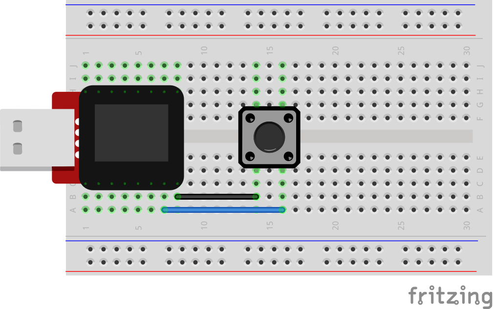
Breadboard Setup
Hook up your circuit as pictured below:
MicroView Arduino Code
language:c
#include <MicroView.h>      // include MicroView library

int buttonPin = A0;         // push button pin
int buttonState = 0;        // variable to store the pushbutton status

void setup() {
    uView.begin();          // start MicroView
    uView.clear(PAGE);      // clear page

    pinMode(buttonPin, INPUT);      // initialize the pushbutton pin as an input
    digitalWrite(buttonPin,HIGH);   // set Internal pull-up
}

void loop() {
    buttonState = digitalRead(buttonPin);   // read the state of the pushbutton value

    // check if the pushbutton is pressed.
    // if it is not pressed, the buttonState is HIGH:
    if (buttonState == HIGH) {
        uView.setCursor(0,0);       // set cursor at 0,0
        uView.print("OFF");         // print OFF
        uView.display();
    }
    else {
        uView.setCursor(0,0);
        uView.print("ON ");
        uView.display();
  }
}
What You Should See
You should see your MicroView print "ON" if you push the button, and "OFF" if you let go. (See the code to find out why!) If it isn't working, make sure you have assembled the circuit correctly and verified and uploaded the code to your MicroView or see the troubleshooting tips below.
Code to Note
The digital pins can be used as inputs as well as outputs. Before you do either, you need to tell the MicroView which direction you're going.
pinMode(buttonPin, INPUT);
To read a digital input, you use the digitalRead() function. It will return HIGH if there's 5V present at the pin, or LOW if there's 0V present at the pin.
buttonState = digitalRead(buttonPin);
Because we've connected the button to GND, it will read LOW when it's being pressed. Here we're using the "equivalence" operator ("==") to see if the button is being pressed.
if (buttonState == LOW)
Troubleshooting
Light Not Turning On
The pushbutton is square, and because of this it is easy to put it in the wrong way. Rotate the button by 90 degrees and see if it starts working.
Underwhelmed
No worries, these circuits are all super stripped down to make playing with the components easy, but once you throw them together the sky is the limit.
Still No Success?
A broken circuit is no fun, send us an e-mail and we will get back to you as soon as we can: TechSupport@sparkfun.com
Getting Logical
One of the things that makes the MicroView so useful is that it can make complex decisions based on the input it's getting. For example, you could make a thermostat that turns on a heater if it gets too cold, a fan if it gets too hot, waters your plants if they get too dry, etc.

You can combine these functions to build complex if() statements.
if ((mode == heat) && ((temperature < threshold) || (override == true))) {
    digitalWrite(HEATER, HIGH);
}
...will turn on a heater if you're in heating mode AND the temperature is low, OR if you turn on a manual override. Using these logic operators, you can program your MicroView to make intelligent decisions and take control of the world around it! To learn more about logic, check out our tutorial on digital logic.
To learn more about the different types of buttons and switches you can use in your projects, visit the Switch Basics tutorial.
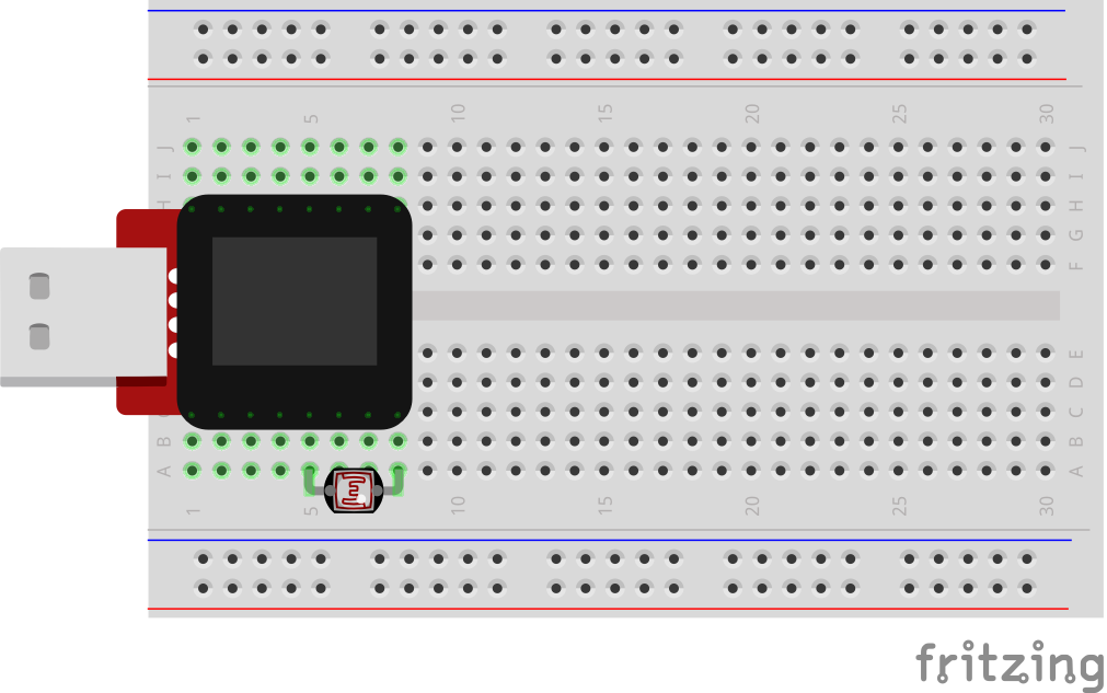
Experiment 5: Photoresistors
You’ve already played with a potentiometer, which varies resistance based on the twisting of a knob. In this circuit, you’ll be using a photoresistor (also known as a photocell), which changes resistance based on how much light the sensor receives.
Parts Needed
You will need the following parts:
- 1x Photoresistor
Breadboard Setup
Hook up your circuit as pictured below:
MicroView Arduino Code
language:c
#include <MicroView.h>      // include MicroView library

MicroViewWidget *widget;    // declare widget pointer

int sensorPin = A2;     // select the input pin for the photoresistor
int sensorValue = 0;    // variable to store the value coming from the sensor

void setup() {
    pinMode(sensorPin,INPUT);       // set sensor pin as INPUT
    digitalWrite(sensorPin,HIGH);   // set Internal pull-up
    uView.begin();                  // start MicrView
    uView.clear(PAGE);              // clear page
    widget = new MicroViewGauge(32,24,0,1023,WIDGETSTYLE1); // set widget as gauge STYLE1
}

void loop() {
    sensorValue= analogRead(sensorPin);     // read value from sensorPin
    widget->setValue(sensorValue);          // set the sensorValue to the gauge widget
    uView.display();                        // display the widget
}
What You Should See
You should see the potentiometer value being displayed on the MicroView's display.
Code to Note
A “variable” is a stored value you’ve given a name to. You must introduce, or "declare" variables before you use them; here we're declaring a variable called sensorValue, of type "int" (integer). Don't forget that variable names are case-sensitive!
int sensorValue;
We use the analogRead() function to read the value on an analog pin. analogRead() takes one parameter, the analog pin you want to use ("sensorPin"), and returns a number ("sensorValue") between 0 (0 volts) and 1023 (5 volts).
sensorValue = analogRead(sensorPin);
Troubleshooting
Sporadically Working
This is most likely due to a slightly dodgy connection with the photoresistor's pins. This can usually be conquered by pushing the photoresistor down into the breadboard.
Still No Success?
A broken circuit is no fun, send us an e-mail and we will get back to you as soon as we can: TechSupport@sparkfun.com
Pull-up Resistors
Many of the sensors you'll use (potentiometers, photoresistors, etc.) are resistors in disguise. Their resistance changes in proportion to whatever they're sensing (light level, temperature, sound, etc.).
The MicroView's analog input pins measure voltage, not resistance. But we can easily read voltage by using the MicroView's internal pull-up resistors. Visit our pull-up resistors tutorial for more info. To get the most out of your photoresistor, we recommend replacing one of the resistors in a voltage divider circuit with a photoresistor.
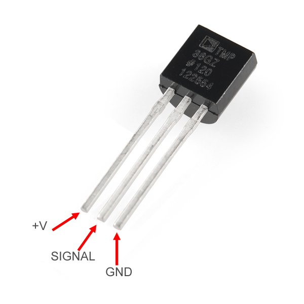
Experiment 6: Temperature Sensor
A temperature sensor is exactly what it sounds like – a sensor used to measure ambient temperature. This particular sensor has three pins – a positive, a ground, and a signal. This is a linear temperature sensor. A change in temperature of one degree centigrade is equal to a change of 10 millivolts at the sensor output. The TMP36 sensor has a nominal 750 mV at 25°C (about room temperature). In this circuit, you’ll learn how to integrate the temperature sensor with your MicroView, and use the serial monitor to display the temperature.
Parts Needed
You will need the following parts:
- 1x TMP36 Temperature Sensor
- 2x Jumper Wire
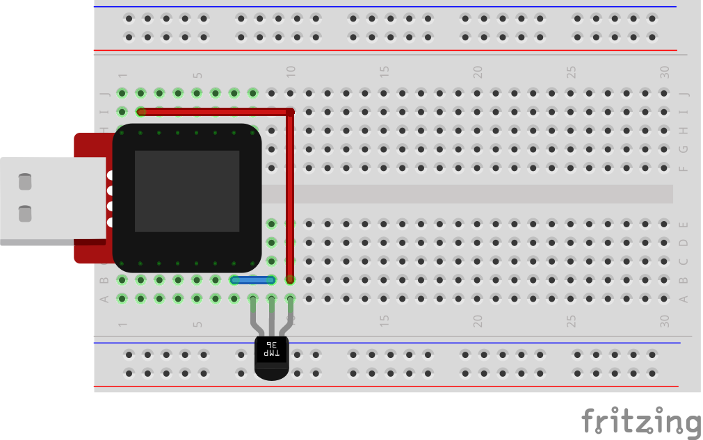
Breadboard Setup
Hook up your circuit as pictured below:
Be sure to insert the TMP36 in the correct orientation. It is polarized and will not work if inserted incorrectly.
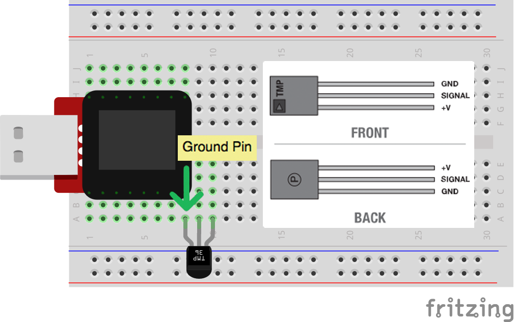
Once you are sure orientation is correct, you can place the remaining jumper wires.
MicroView Arduino Code
language:c
#include <MicroView.h>      // include MicroView library

MicroViewWidget *widget;    // declare widget pointer

int sensorPin = A0;     // select the input pin for the temperature sensor
int sensorValue = 0;    // variable to store the value coming from the sensor

void setup() {
    pinMode(sensorPin,INPUT);   // set sensor pin as INPUT
    uView.begin();              // start MicroView
    uView.clear(PAGE);          // clear page
    widget = new MicroViewGauge(32,24,0,255,WIDGETSTYLE1);      // declare as gauge widget
    uView.drawChar(47,33,67);   // Character C is ASCII code 67
}

void loop() {
    sensorValue= analogRead(sensorPin);             // read sensor pin value
    float voltage = sensorValue * 5.0;              // voltage at pin in volt
    voltage /= 1024.0;                              // voltage = sensorValue x (5/1024)
    float temperatureC = (voltage - 0.5) * 100 ;    // C = (voltage - 0.5) x 100
    widget->setValue(temperatureC);                 // set temperature value to the gauge
    uView.display();                                // display gauge tick
}
What You Should See
As you warm and cool your temperature sensor, you should be able to see the gauge on your MicroView's display go up or down.
Troubleshooting
Temperature Value is Unchanging
Try pinching the sensor with your fingers to heat it up or pressing a bag of ice against it to cool it down.
Still No Success?
A broken circuit is no fun, send us an e-mail and we will get back to you as soon as we can: TechSupport@sparkfun.com
Experiment 7: Servo Motors
Servos are ideal for embedded electronics applications because they do one thing very well that motors cannot – they can move to a position accurately. By varying the pulse width of the output voltage to a servo, you can move a servo to a specific position. For example, a pulse of 1.5 milliseconds will move the servo 90 degrees. In this circuit, you’ll learn how to use PWM (pulse width modulation) to control and rotate a servo. To learn more about PWM, visit our tutorial.
Parts Needed
You will need the following parts:
- 1x Servo Motor
- 3x Jumper Wire
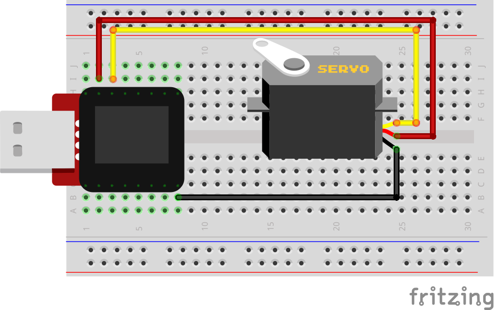
Breadboard Setup
Connect 3x jumper wires to the female 3 pin header on the servo. This will make it easier to breadboard the servo.
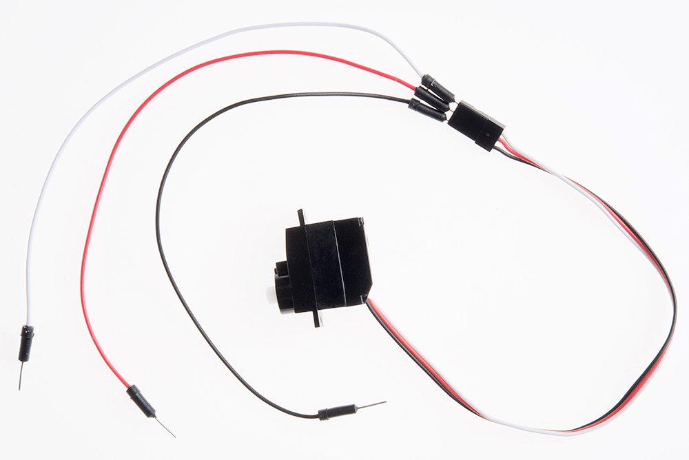
Hook up your circuit as pictured below:
MicroView Arduino Code
language:c
#include <MicroView.h>      // include MicroView library
#include <Servo.h>          // include Servo library

Servo servo;                // declare servo object

void setup()
{
    uView.begin();          // start MicroView
    uView.clear(PAGE);      // clear page
    servo.attach(6);        // servo control pin at D6
}

void loop()
{
    uView.setCursor(0,0);   // set cursor to 0,0
    uView.print("Mid  ");   // display Mid
    uView.display();
    servo.write(90);    // about 90 degree
    delay(2000);        // delay 2 seconds

    uView.setCursor(0,0);
    uView.print("Left ");
    uView.display();
    servo.write(20);    //  about 20 degree
    delay(2000);

    uView.setCursor(0,0);
    uView.print("Mid  ");
    uView.display();
    servo.write(90);    // about 90 degree
    delay(2000);

    uView.setCursor(0,0);
    uView.print("Right");
    uView.display();
    servo.write(160);   // about 160 degree
    delay(2000);
}
What You Should See
You should see your servo motor move to various locations at several speeds. If the motor doesn't move, check your connections and make sure you have verified and uploaded the code, or see the troubleshooting tips below.
Code to Note
#include is a special "preprocessor" command that inserts a library (or any other file) into your sketch. You can type this command yourself, or choose an installed library from the "sketch / import library" menu.
#include <Servo.h>
The servo library adds new commands that let you control a servo. To prepare the Arduino to control a servo, you must first create a Servo "object" for each servo (here we've named it "servo"), and then "attach" it to a digital pin (here we're using digital pin 6).
Servo servo;
servo.attach(6);
The servo in this kit doesn't spin all the way around, but they can be commanded to move to a specific position. We use the servo library's write() command to move a servo to a specified number of degrees(0 to 160). Remember that the servo requires time to move, so give it a short delay() if necessary.
servo.write(160);
Troubleshooting
Servo Not Twisting
Even with colored wires it is still shockingly easy to plug a servo in backward. This might be the case.
Still Not Working
A mistake we made a time or two was simply forgetting to connect the power (red and brown wires) to +5 volts and ground.
Fits and Starts
If the servo begins moving then twitches, and there's a flashing light on your MicroView, the power supply you are using is not quite up to the challenge. Try using a USB adapter that provides more current.
Still No Success?
A broken circuit is no fun, send us an e-mail and we will get back to you as soon as we can: TechSupport@sparkfun.com
Experiment 8: Piezo Buzzer
Introduction
In this circuit, we'll again bridge the gap between the digital world and the analog world. We'll be using a Piezo buzzer that makes a small "click" when you apply voltage to it (try it!). By itself that isn't terribly exciting, but if you turn the voltage on and off hundreds of times a second, the buzzer will produce a tone. And if you string a bunch of tones together, you've got music! This circuit and sketch will play a classic tune. We'll never let you down!
Parts Needed
You will need the following parts:
- 1x Piezo Buzzer
- 2x Jumper Wires
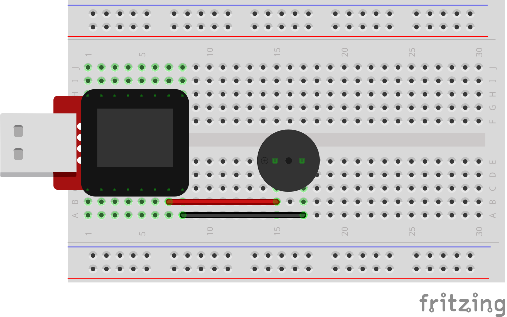
Breadboard Setup
Hook up your circuit as pictured below:
MicroView Arduino Code
language:c
#include <MicroView.h>
// adapted from SparkFun Inventor Kit https://www.sparkfun.com/products/12001
// Please download the original source code for detail comment of the source code
// http://cdn.sparkfun.com/datasheets/Kits/SIK%20Guide%20Code.zip

const int buzzerPin = A0;
const int songLength = 18;
char notes[] = "cdfda ag cdfdg gf "; // a space represents a rest
int beats[] = {1,1,1,1,1,1,4,4,2,1,1,1,1,1,1,4,4,2};

int tempo = 150;

void setup()
{
    uView.begin();
    uView.clear(PAGE);
    pinMode(buzzerPin, OUTPUT);
}

void loop()
{
    int i, duration;

    for (i = 0; i < songLength; i++) // step through the song arrays
    {
        duration = beats[i] * tempo;  // length of note/rest in ms

        if (notes[i] == ' ')          // is this a rest?
        {
            uView.print(" ");
            uView.display();
            delay(duration);            // then pause for a moment
        }
        else                          // otherwise, play the note
        {
            uView.print(notes[i]);
            uView.display();
            tone(buzzerPin, frequency(notes[i]), duration);
            delay(duration);            // wait for tone to finish
        }
        delay(tempo/10);              // brief pause between notes
    }

    // We only want to play the song once, so we'll pause forever:
    while(true){}
    // If you'd like your song to play over and over,
    // remove the above statement
}


int frequency(char note)
{
    // This function takes a note character (a-g), and returns the
    // corresponding frequency in Hz for the tone() function.

    int i;
    const int numNotes = 8;  // number of notes we're storing

    // The following arrays hold the note characters and their
    // corresponding frequencies. The last "C" note is uppercase
    // to separate it from the first lowercase "c". If you want to
    // add more notes, you'll need to use unique characters.

    // For the "char" (character) type, we put single characters
    // in single quotes.

    char names[] = { 'c', 'd', 'e', 'f', 'g', 'a', 'b', 'C' };
    int frequencies[] = {262, 294, 330, 349, 392, 440, 494, 523};

    // Now we'll search through the letters in the array, and if
    // we find it, we'll return the frequency for that note.

    for (i = 0; i < numNotes; i++)  // Step through the notes
    {
        if (names[i] == note)         // Is this the one?
        {
            return(frequencies[i]);     // Yes! Return the frequency
        }
    }
    return(0);  // We looked through everything and didn't find it,
    // but we still need to return a value, so return 0.
}
What You Should See
You should see - well, nothing; but you should be able to hear a song. If it isn't working, make sure you have assembled the circuit correctly and verified and uploaded the code to your MicroView or see the troubleshooting tips below.
Code to Note
Up until now we've been working solely with numerical data, but the Arduino can also work with text. Characters (single, printable, letters, numbers and other symbols) have their own type, called "char". When you have an array of characters, it can be defined between double-quotes (also called a "string"), OR as a list of single-quoted characters.
char notes[] = "cdfda ag cdfdg gf ";
char names[] = {'c','d','e','f','g','a','b','C'};
One of Arduino's many useful built-in commands is the tone() function. This function drives an output pin at a certain frequency, making it perfect for driving buzzers and speakers. If you give it a duration (in milliseconds), it will play the tone then stop. If you don't give it a duration, it will keep playing the tone forever (but you can stop it with another function, noTone() ).
tone(pin, frequency, duration);
Troubleshooting
No Sound
Given the size and shape of the piezo element it is easy to miss the right holes on the breadboard. Try double checking its placement.
Can't Think While the Melody is Playing
Just pull up the piezo element whilst you think, upload your program then plug it back in.
Still No Success?
A broken circuit is no fun, send us an e-mail and we will get back to you as soon as we can: TechSupport@sparkfun.com
Experiment 9: Spinning a Motor
Introduction
Remember before when you played around with a servo motor? Now we are going to tackle spinning a motor. This requires the use of a transistor, which can switch a larger amount of current than the MicroView can. When using a transistor, you just need to make sure its maximum specs are high enough for your use. The transistor we are using for this circuit is rated at 40V max and 200 milliamps max – perfect for our toy motor! When the motor is spinning and suddenly turned off, the magnetic field inside it collapses, generating a voltage spike. This can damage the transistor. To prevent this, we use a "flyback diode", which diverts the voltage spike around the transistor.
Parts Needed
You will need the following parts:
- 1x 330Ω resistor (Orange Orange Brown Gold)
- 1x Transistor
- 1x Diode
- 1x Motor
- 4x Jumper Wires
Breadboard Setup
Pay close attention when building this circuit as there are two polarized parts that must be inserted into the breadboard correctly in order for this circuit to work.
The first polarized part is the transistor.
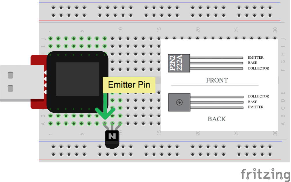
The second is the diode.
Hook up the rest of your circuit as pictured below:

MicroView Arduino Code
language:c
#include <MicroView.h>      // include MicroView library

int motorPIN = 3;           // set motor control pin
MicroViewWidget *widget;    // declare widget pointer

void setup() {
    uView.begin();          // start MicroView
    uView.clear(PAGE);      // clear page
    pinMode(motorPIN, OUTPUT);      // initialize the digital pin as an output.
    widget = new MicroViewGauge(32,24,90,255,WIDGETSTYLE1);     // set widget as gauge STYLE1
    setPwmFrequency(motorPIN,1);    // set PWM frequency to about 31K
}

void loop() {
    for (int i=90;i<255;i+=10) {    // step i from 90 to 255 by step of 10
        widget->setValue(i);        // set i value to gauge
        uView.display();            // display gauge
        analogWrite(motorPIN, i);   // set the DUTY cycle of the motorPIN
        delay(500);                 // delay 500 ms
    }
}

// function to set the frequency of the PWM pin
// adapted from http://playground.arduino.cc/Code/PwmFrequency
void setPwmFrequency(int pin, int divisor) {
    byte mode;
    if(pin == 5 || pin == 6 || pin == 9 || pin == 10) {
        switch(divisor) {
        case 1: mode = 0x01; break;
        case 8: mode = 0x02; break;
        case 64: mode = 0x03; break;
        case 256: mode = 0x04; break;
        case 1024: mode = 0x05; break;
        default: return;
        }
        if(pin == 5 || pin == 6) {
            TCCR0B = TCCR0B & 0b11111000 | mode;
        } else {
            TCCR1B = TCCR1B & 0b11111000 | mode;
        }
    } else if(pin == 3 || pin == 11) {
        switch(divisor) {
        case 1: mode = 0x01; break;
        case 8: mode = 0x02; break;
        case 32: mode = 0x03; break;
        case 64: mode = 0x04; break;
        case 128: mode = 0x05; break;
        case 256: mode = 0x06; break;
        case 1024: mode = 0x7; break;
        default: return;
        }
        TCCR2B = TCCR2B & 0b11111000 | mode;
    }
}
What You Should See
The DC Motor should spin if you have assembled the circuit’s components correctly, and also verified/uploaded the correct code. If your circuit is not working check the troubleshooting section below.
Code to Note
In this code, we use the command setPwmFrequency(motorPIN,1); to call a function (an encapsulated section of resuable code) for setting the PWM Frequency. Pulse Width Modulation, or PWM, is a technique for getting analog results with digital means. Digital control is used to create a square wave, a signal switched between on and off.
The setPwmFrequency function is defined on line 25.
void setPwmFrequency(int pin, int divisor){
  ...
}
Troubleshooting
USB Port not providing enough power or tripping?
Some USB ports don't provide enough current to spin the motor. If that's the case with a USB port on your computer we recommend powering your MicroView and motor with a powered USB hub or by using batteries. Checkout this circuit for powering your motor with batteries.
Motor Not Spinning
If you sourced your own transistor, double check with the data sheet that the pinout is compatible with a P2N2222AG (many are reversed).
Still No Luck
If you sourced your own motor, double check that it will work with 5 volts and that it does not draw too much power.
Still No Success?
A broken circuit is no fun, send us an e-mail and we will get back to you as soon as we can: TechSupport@sparkfun.com
Experiment 10: Relays
A relay is basically an electrically controlled mechanical switch. Inside that harmless looking plastic box is an electromagnet that, when it gets a jolt of energy, causes a switch to trip. In this circuit, you’ll learn how to control a relay like a pro – giving your MicroView even more powerful abilities!
Parts Needed
You will need the following parts:
- 2x 330Ω resistor (Orange Orange Brown Gold)
- 1x Transistor
- 1x Diode
- 1x Yellow LED
- 1x Red LED
- 1x Relay
- 11x Jumper Wires
Breadboard Setup
Hook up your circuit as pictured below. Be cautious of polarized parts. Refer back to previous experiments to see how each component is oriented. For the relay, pay attention to which side has two pins and which has three pins.

MicroView Arduino Code
language:c
#include <MicroView.h>          // include MicroView library

int relayPin = 2;               // set relayPin as pin 2 of Arduino

void setup() {
    uView.begin();              // start MicroView
    uView.clear(PAGE);          // clear page
    pinMode(relayPin, OUTPUT);  // initialize the digital pin as an output.
}

void loop() {
    uView.setCursor(0,0);           // set cursor at 0,0
    uView.print("YELLOW");          // print YELLOW text
    uView.display();                // display
    digitalWrite(relayPin, HIGH);   // turn the RELAY ON (HIGH is the voltage level)
    delay(1000);                    // wait for a second

    uView.setCursor(0,0);
    uView.print("RED   ");
    uView.display();
    digitalWrite(relayPin, LOW);    // turn the RELAY off by making the voltage LOW
    delay(1000);                    // wait for a second
}
What You Should See
You should be able to hear the relay contacts click, and see the two LEDs alternate illuminating at 1-second intervals. If you don't, double-check that you have assembled the circuit correctly, and uploaded the correct sketch to the MicroView. Also, see the troubleshooting tips below.
Code to Note
When we turn on the transistor, which in turn energizes the relay's coil, the relay's switch contacts are closed. This connects the relay's COM pin to the NO (Normally Open) pin. Whatever you've connected using these pins will turn on. (Here we're using LEDs, but this could be almost anything.)
digitalWrite(relayPin, HIGH);
The relay has an additional contact called NC (Normally Closed). The NC pin is connected to the COM pin when the relay is OFF. You can use either pin depending on whether something should be normally on or normally off. You can also use both pins to alternate power to two devices, much like railroad crossing warning lights.
digitalWrite(relayPin, LOW);
Troubleshooting
LEDs Not Lighting
Double-check that you've plugged them in correctly. The longer lead (and non-flat edge of the plastic flange) is the positive lead.
No Clicking Sound
The transistor or coil portion of the circuit isn't quite working. Check the transistor is plugged in the right way.
Not Quite Working
The included relays are designed to be soldered rather than used in a breadboard. As such you may need to press it in to ensure it works (and it may pop out occasionally). When you’re building the circuit be careful not to mix up the temperature sensor and the transistor, they’re almost identical.
Still No Success?
A broken circuit is no fun, send us an e-mail and we will get back to you as soon as we can: TechSupport@sparkfun.com
Experiment 11: Soft Potentiometer
Introduction
In this circuit you’ll work with a soft potentiometer. Back in Experiment 2, you used a regular potentiometer to vary the resistance of a circuit. With the soft pot, you can do all the same things you would with a regular potentiometer. However, this time the interface changes, showing you how you can accomplish the same tasks with different forms of the same technology or with different technologies altogether.
Parts Needed
You will need the following parts:
- 1x Soft Potentiometer
- 2x 330Ω resistor (Orange Orange Brown Gold)
- 2x Jumper Wires
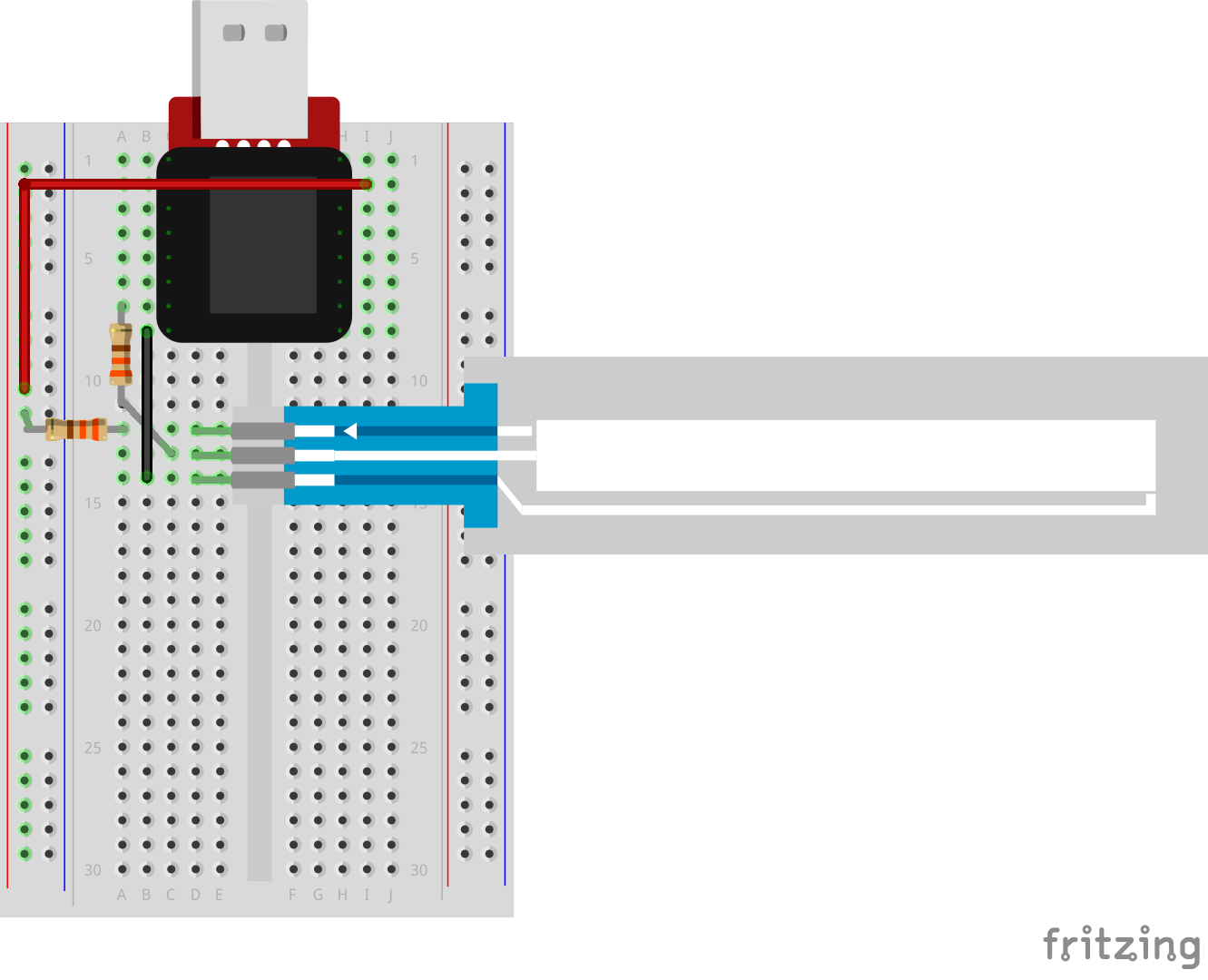
Breadboard Setup
Hook up your circuit as pictured below. The soft pot is polarized, so pay attention to its orientation. The side with the adhesive back is the bottom, and the side with the touch strips is the top (as pictured below).
MicroView Arduino Code
language:c
#include <MicroView.h>              // include MicroView library

MicroViewWidget  *widget;           // declare widget pointer

int sensorValue;                    // declare variable to store sensor value
int sensorPin=A0;                   // declare sensor pin as A0 of Arduino

void setup() {
  uView.begin();                    // start MicroView
  uView.clear(PAGE);                // clear page
  widget = new MicroViewSlider(0,0,0,1024, WIDGETSTYLE1);   // declare widget as slider
  pinMode(sensorPin, INPUT);                // set sensor pin as INPUT
}

void loop () {
  sensorValue=analogRead(sensorPin);        // read and store sensor value
  widget->setValue(sensorValue);            // set sensor value to widget
  uView.display();                          // display widget
  delay(20);                                // delay 20 ms
}
What You Should See
As you move a blunt long object (like your finger) up and down the soft potentiometer, the MicroView Slider Widget should change it's value accordingly. If it isn't working, make sure you have assembled the circuit correctly and verified and uploaded the code to your MicroView, or see the troubleshooting tips below.
Troubleshooting
Bizarre Results
The most likely cause of this is if you’re pressing the potentiometer in more than one position. This is normal and can actually be used to create some neat results.
Still No Success?
A broken circuit is no fun, send us an e-mail and we will get back to you as soon as we can: TechSupport@sparkfun.com
Resources and Going Further
Congratulations, you have completed the SparkFun Inventor's Kit for MicroView! From here, the world is your oyster. Here are some more resources to aid in your understanding of the MicroView.
- MicroView GitHub Repository - All the source files for everything MicroView related.
- Explore the MicroView Library - Learn about the functions that control the MicroView and its OLED screen.
- Creating Your Own Fonts for the MicroView - Learn how to fully utilize the OLED screen embedded within the MicroView.
- MicroView Bootloader Installation - Should you ever need to reflash the bootloader on your MicroView, we have an extensive guide covering that process.
Check out these other experiment guides for more learning fun!