SparkFun Inventor's Kit for MicroView
Experiment 10: Relays
A relay is basically an electrically controlled mechanical switch. Inside that harmless looking plastic box is an electromagnet that, when it gets a jolt of energy, causes a switch to trip. In this circuit, you’ll learn how to control a relay like a pro – giving your MicroView even more powerful abilities!
Parts Needed
You will need the following parts:
- 2x 330Ω resistor (Orange Orange Brown Gold)
- 1x Transistor
- 1x Diode
- 1x Yellow LED
- 1x Red LED
- 1x Relay
- 11x Jumper Wires
Breadboard Setup
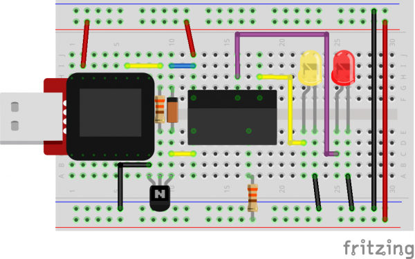
Hook up your circuit as pictured below. Be cautious of polarized parts. Refer back to previous experiments to see how each component is oriented. For the relay, pay attention to which side has two pins and which has three pins.
MicroView Arduino Code
language:c
#include <MicroView.h>          // include MicroView library

int relayPin = 2;               // set relayPin as pin 2 of Arduino

void setup() {
    uView.begin();              // start MicroView
    uView.clear(PAGE);          // clear page
    pinMode(relayPin, OUTPUT);  // initialize the digital pin as an output.
}

void loop() {
    uView.setCursor(0,0);           // set cursor at 0,0
    uView.print("YELLOW");          // print YELLOW text
    uView.display();                // display
    digitalWrite(relayPin, HIGH);   // turn the RELAY ON (HIGH is the voltage level)
    delay(1000);                    // wait for a second

    uView.setCursor(0,0);
    uView.print("RED   ");
    uView.display();
    digitalWrite(relayPin, LOW);    // turn the RELAY off by making the voltage LOW
    delay(1000);                    // wait for a second
}
What You Should See
You should be able to hear the relay contacts click, and see the two LEDs alternate illuminating at 1-second intervals. If you don't, double-check that you have assembled the circuit correctly, and uploaded the correct sketch to the MicroView. Also, see the troubleshooting tips below.
Code to Note
When we turn on the transistor, which in turn energizes the relay's coil, the relay's switch contacts are closed. This connects the relay's COM pin to the NO (Normally Open) pin. Whatever you've connected using these pins will turn on. (Here we're using LEDs, but this could be almost anything.)
digitalWrite(relayPin, HIGH);
The relay has an additional contact called NC (Normally Closed). The NC pin is connected to the COM pin when the relay is OFF. You can use either pin depending on whether something should be normally on or normally off. You can also use both pins to alternate power to two devices, much like railroad crossing warning lights.
digitalWrite(relayPin, LOW);
Troubleshooting
LEDs Not Lighting
Double-check that you've plugged them in correctly. The longer lead (and non-flat edge of the plastic flange) is the positive lead.
No Clicking Sound
The transistor or coil portion of the circuit isn't quite working. Check the transistor is plugged in the right way.
Not Quite Working
The included relays are designed to be soldered rather than used in a breadboard. As such you may need to press it in to ensure it works (and it may pop out occasionally). When you’re building the circuit be careful not to mix up the temperature sensor and the transistor, they’re almost identical.
Still No Success?
A broken circuit is no fun, send us an e-mail and we will get back to you as soon as we can: TechSupport@sparkfun.com
