SparkFun Arduino UNO R4 WiFi Qwiic Kit Hookup Guide
The Arduino Uno R4 Wifi Board
This board is jam packed with functionality. We'll cover some of the basics here, but to read about the full shebang, refer to the Product Reference Manual.
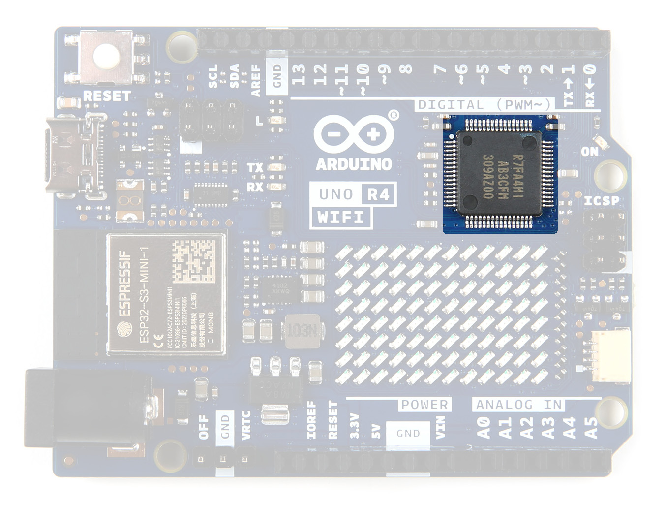
Microcontroller
The Arduino UNO R4 board is equipped with a powerful RA4M1 series 32-bit microcontroller from Renesas, which offers increased processing power, memory, and on-board peripherals. Importantly, these enhancements do not compromise compatibility with existing shields and accessories, nor do they require any changes to the standard form factor or 5V operating voltage.
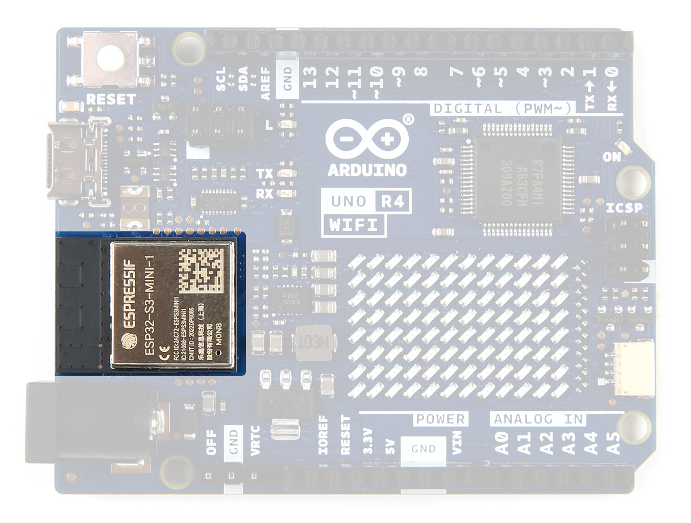
ESP32-S3-MINI CoProcessor
The UNO R4 WiFi features an ESP32-S3-MINI coprocessor that enhances the capabilities of the RA4M1 microcontroller. With WiFi and Bluetooth connectivity, this board allows makers to easily connect to the internet and create IoT projects.
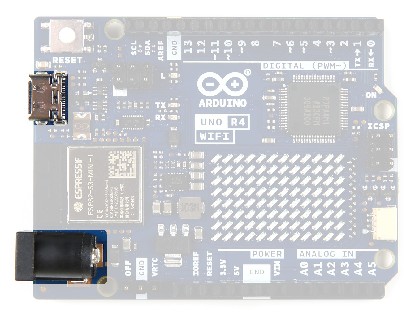
Power
You can provide power via the USB-C connector or the Barrel Jack. A USB-C cable is included in the kit, the Barrel Jack can be purchased separately. The RA4M1's operating voltage is fixed at 5 V, whereas the ESP32-S3 module is 3.3 V. Communication between these two MCUs are performed via a logic level translator (TXB0108DQSR).
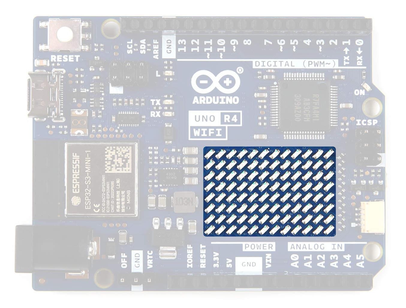
LED Matrix
The UNO R4 WiFi includes a bright 12x8 red LED matrix (96 dots total). This feature is ideal for creative projects using animations or for plotting sensor data, without the need for any additional hardware.
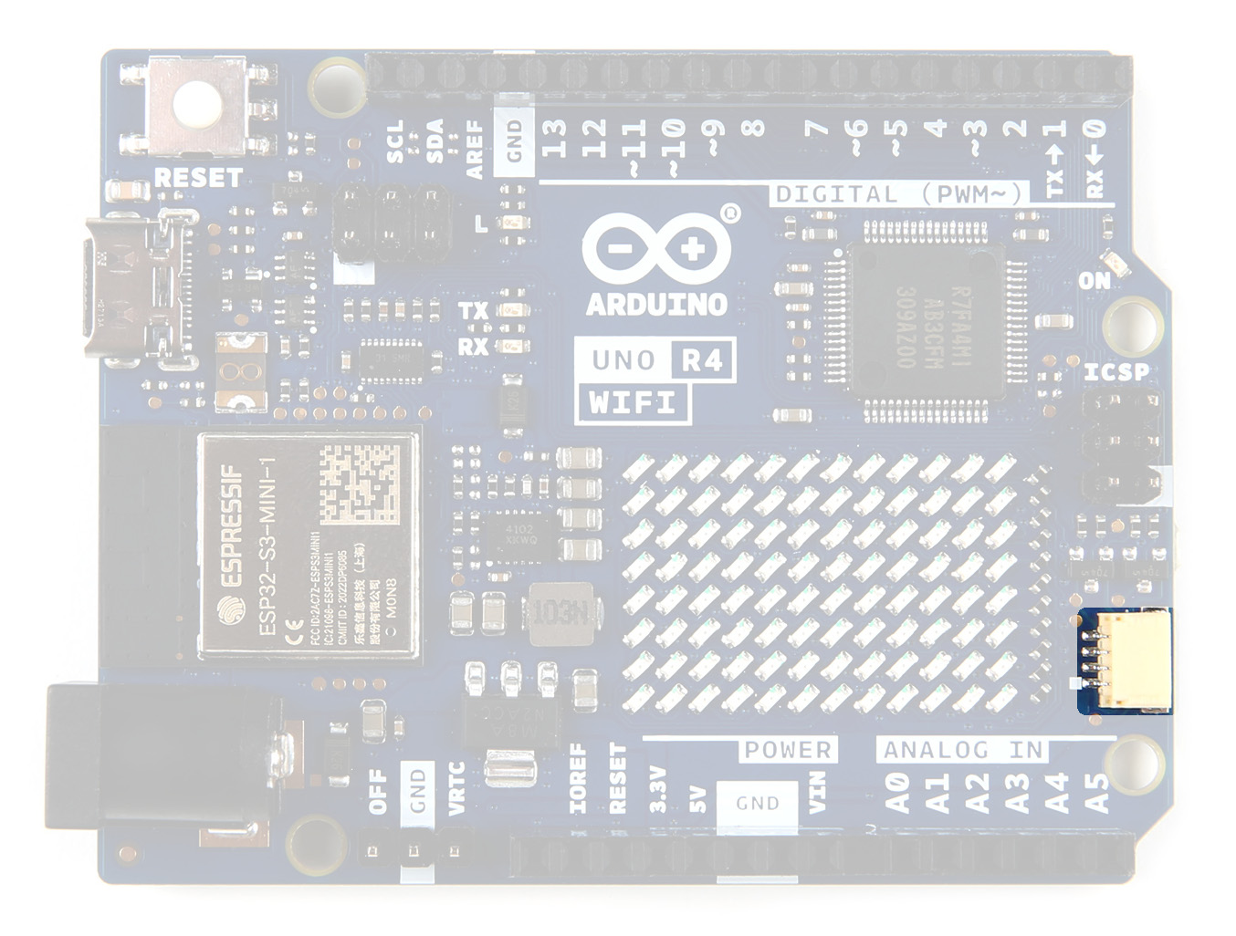
Qwiic Connector
The UNO R4 WiFi includes an industry-standard Qwiic I2C connector that facilitates quick prototyping. With a wide variety of compatible modules that can be connected over I2C, makers can easily create custom projects and expand the capabilities of the UNO R4 WiFi.
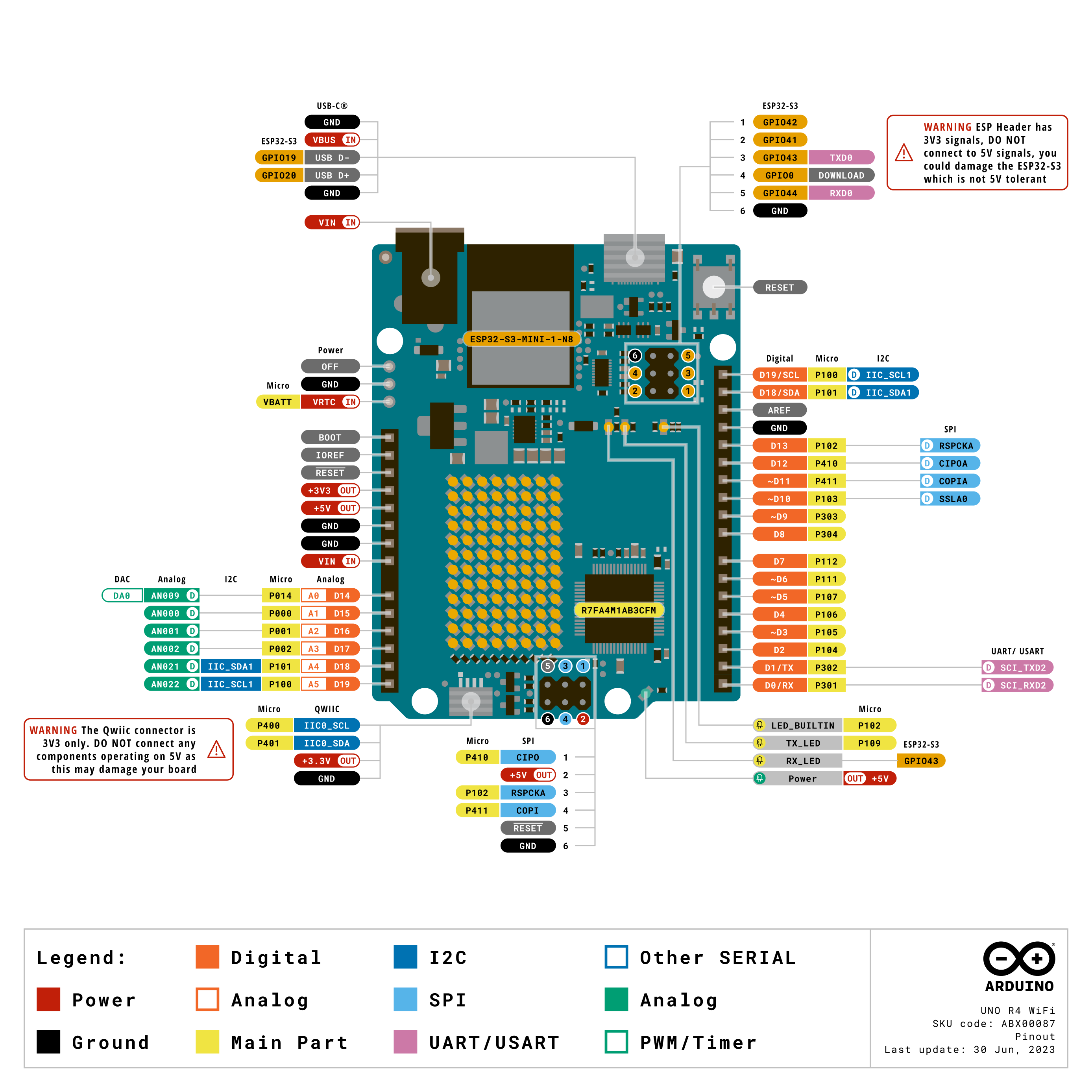
GPIO
The board features 14 digital I/O ports, 6 analog channels, dedicated pins for I2C, SPI and UART connections. The pins on either side of the board are highlighted here.
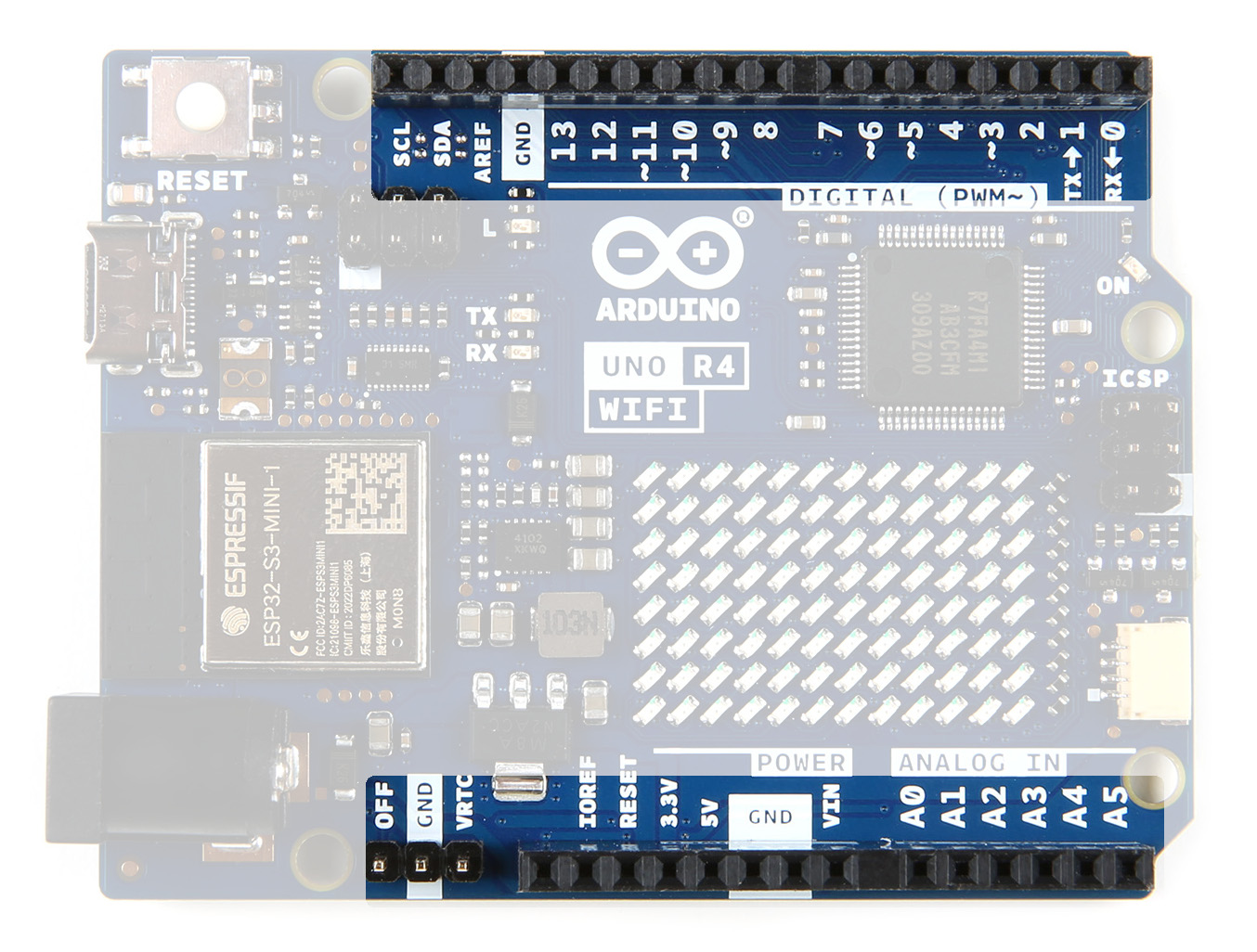
Their functionality is shown below; for more details, refer to the Product Reference Manual.