SparkFun Arduino UNO R4 WiFi Qwiic Kit Hookup Guide
Introduction
The SparkFun Arduino UNO R4 WiFi Qwiic Kit is a great way to get started with Arduino and the Qwiic-connect system. This kit includes everything you need to build a WiFi-enabled project, including an Arduino UNO R4 board, an assortment of Qwiic-enabled sensors and input boards, a Qwiic OLED Display, and a variety of other components to get you connected. Hooking up a handful of inputs and outputs to a Arduino UNO R4 has never been so easy.
The UNO universe expands with the Arduino UNO R4 WiFi: the same industry-standard form factor at 5V operating voltage, but with the enhanced performance of a RA4M1 32-bit microcontroller by Renesas with ESP32-S3-MINI coprocessor – for increased computational power, memory and speed – as well as WiFi® and Bluetooth® connectivity, a 12 x 8 LED matrix, and a Qwiic connector.
The SparkFun Arduino UNO R4 WiFi Qwiic Kit is a great way to learn about Arduino, WiFi, and electronics. With this kit, you can build your own WiFi-enabled projects and start connecting your devices to the Internet of Things.
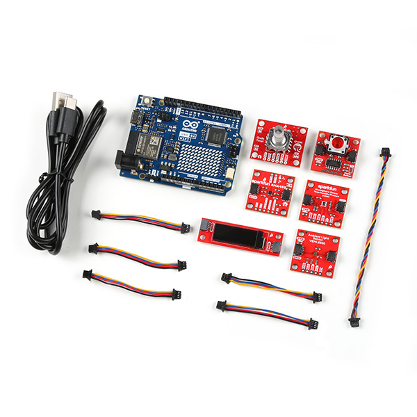
SparkFun Arduino UNO R4 WiFi Qwiic Kit
KIT-22641Parts List
To follow this experiment, you will need the following materials. If you did not order the kit, you may need some of the items here. You may not need everything though, depending on what you have. Add it to your cart, read through the guide, and adjust the cart as necessary.
Suggested Reading
If you aren’t familiar with the following concepts, we recommend checking out these tutorials before continuing.
| Qwiic Connect System |
What is an Arduino?
Installing Arduino IDE
Logic Levels
I2C
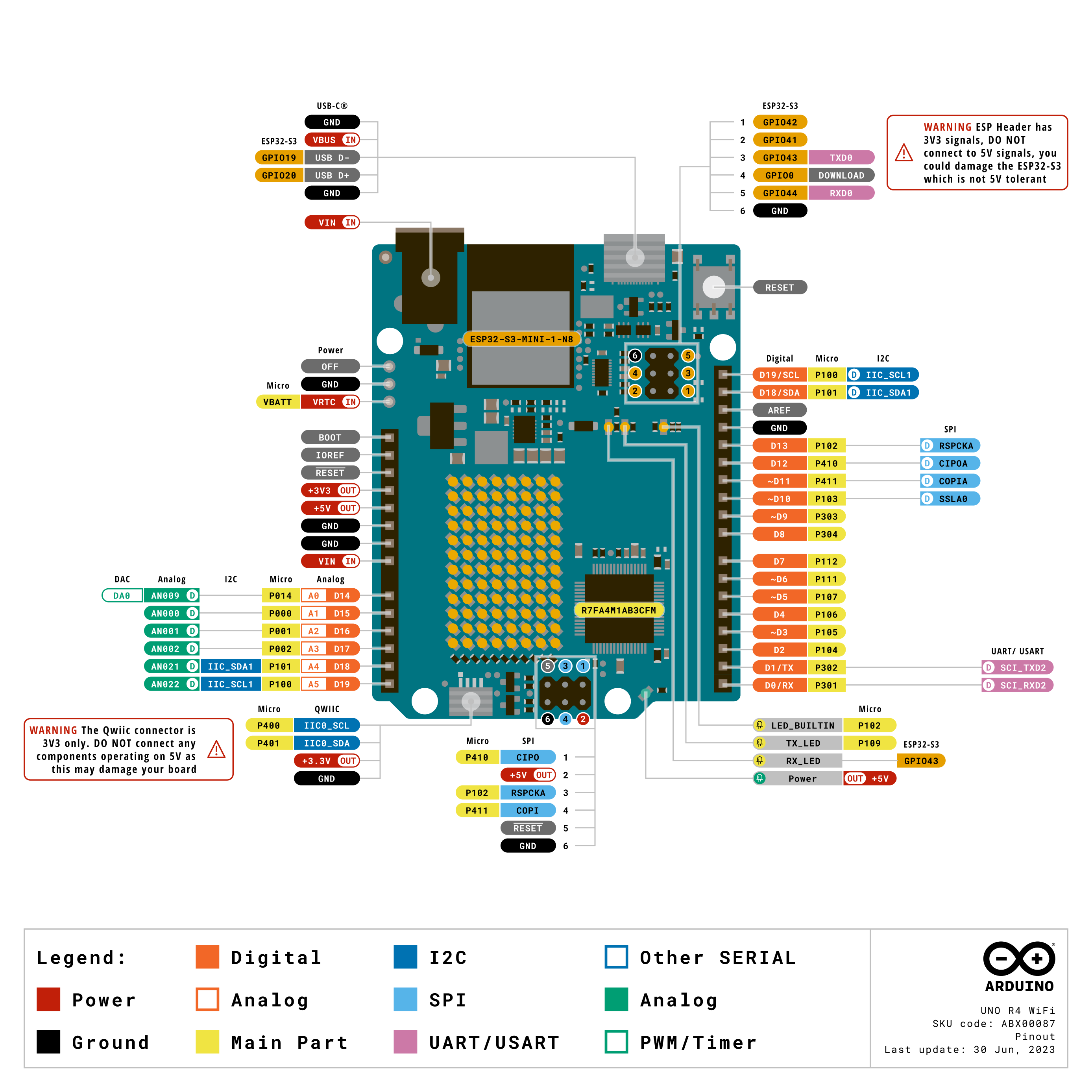
The Arduino Uno R4 Wifi Board
This board is jam packed with functionality. We'll cover some of the basics here, but to read about the full shebang, refer to the Product Reference Manual.
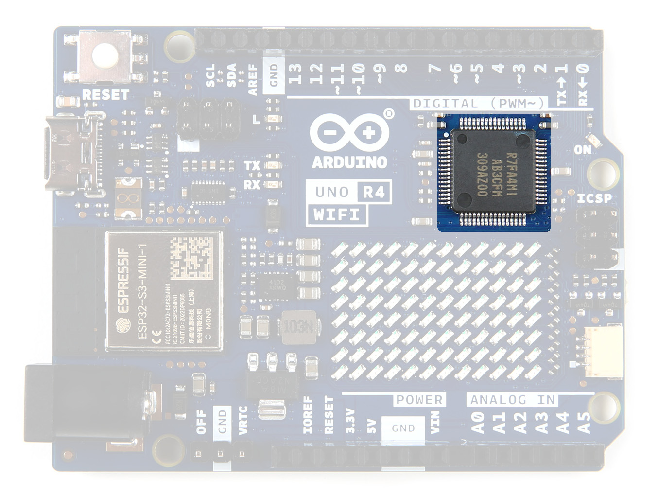
Microcontroller
The Arduino UNO R4 board is equipped with a powerful RA4M1 series 32-bit microcontroller from Renesas, which offers increased processing power, memory, and on-board peripherals. Importantly, these enhancements do not compromise compatibility with existing shields and accessories, nor do they require any changes to the standard form factor or 5V operating voltage.
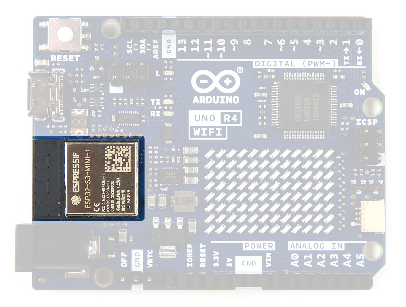
ESP32-S3-MINI CoProcessor
The UNO R4 WiFi features an ESP32-S3-MINI coprocessor that enhances the capabilities of the RA4M1 microcontroller. With WiFi and Bluetooth connectivity, this board allows makers to easily connect to the internet and create IoT projects.
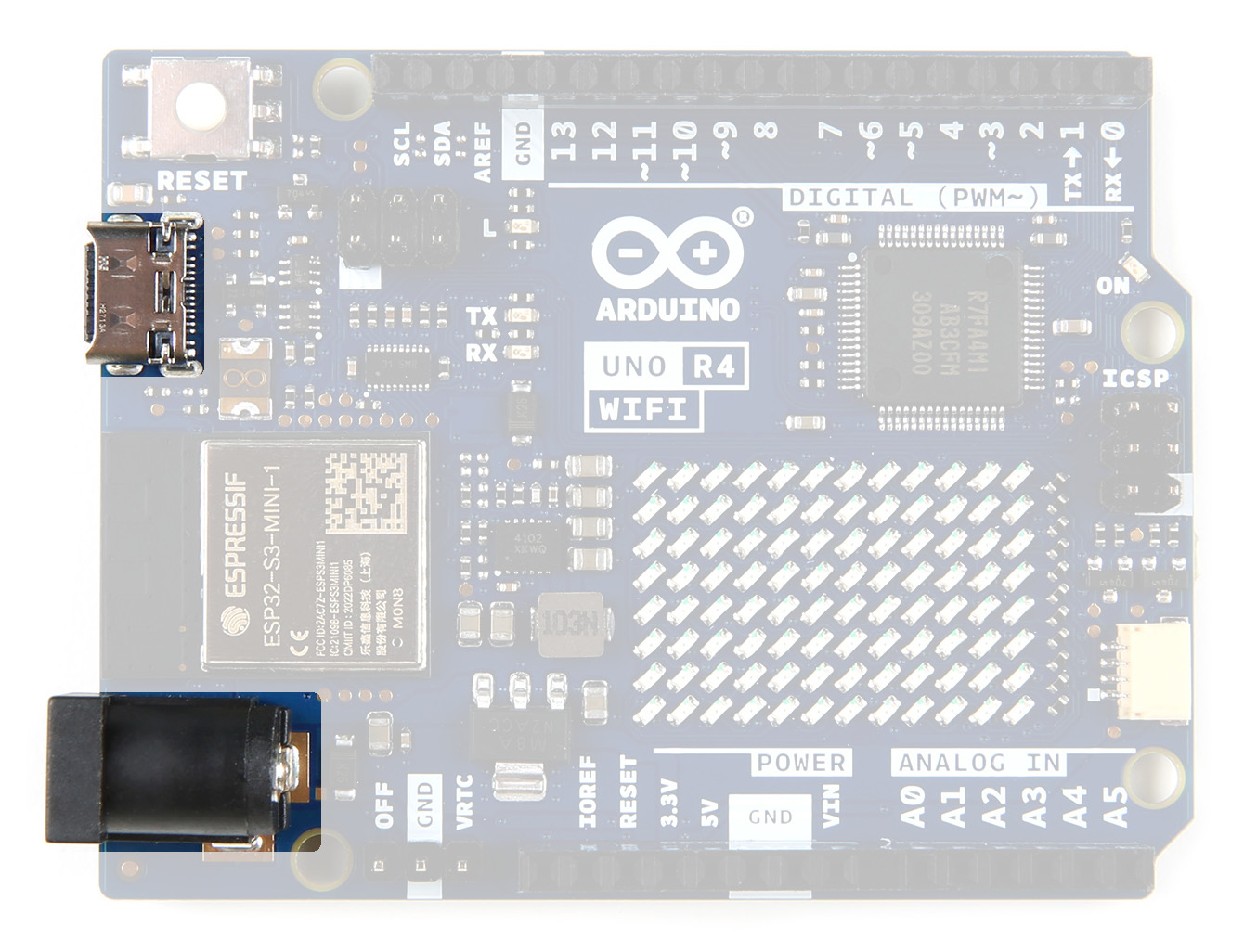
Power
You can provide power via the USB-C connector or the Barrel Jack. A USB-C cable is included in the kit, the Barrel Jack can be purchased separately. The RA4M1's operating voltage is fixed at 5 V, whereas the ESP32-S3 module is 3.3 V. Communication between these two MCUs are performed via a logic level translator (TXB0108DQSR).
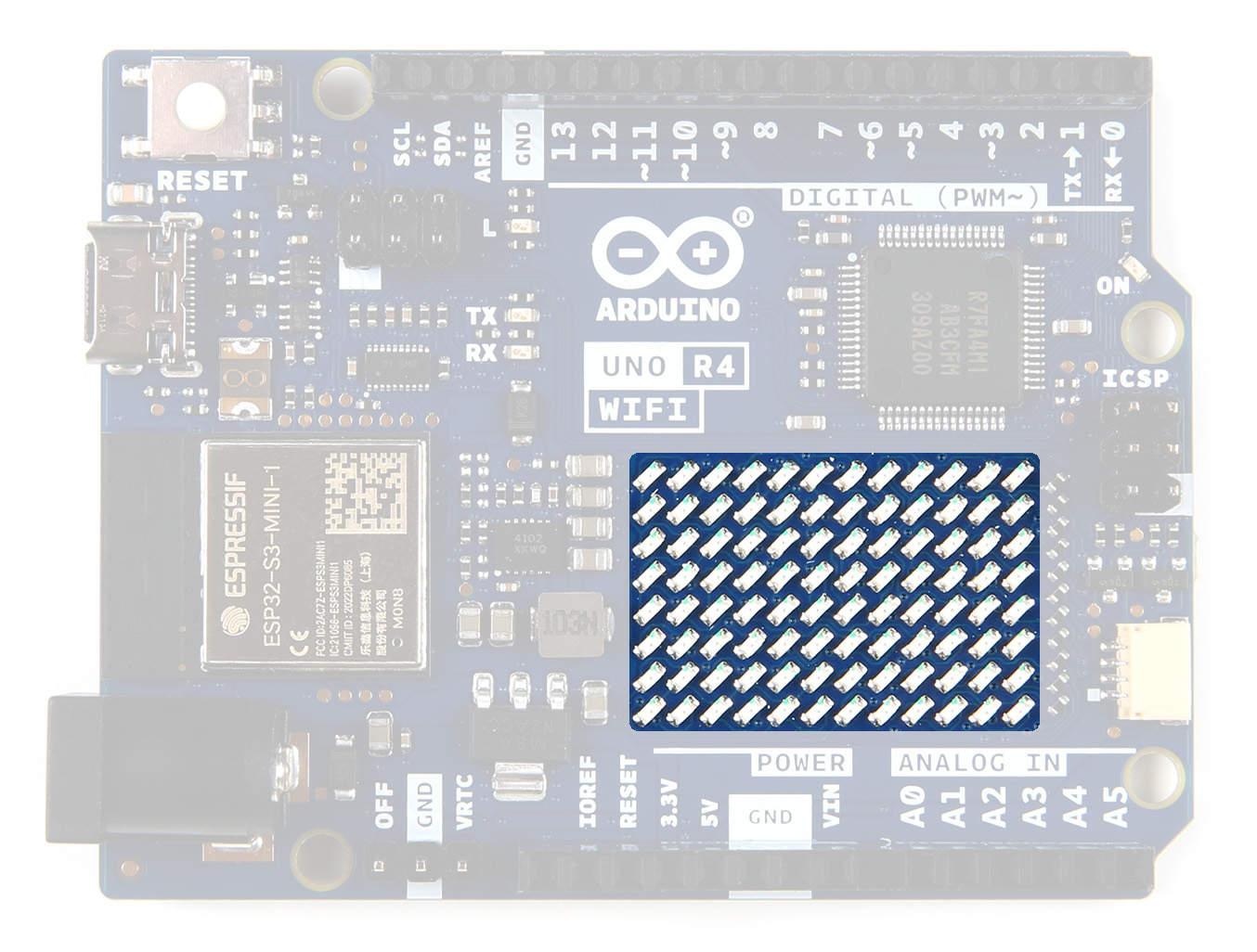
LED Matrix
The UNO R4 WiFi includes a bright 12x8 red LED matrix (96 dots total). This feature is ideal for creative projects using animations or for plotting sensor data, without the need for any additional hardware.
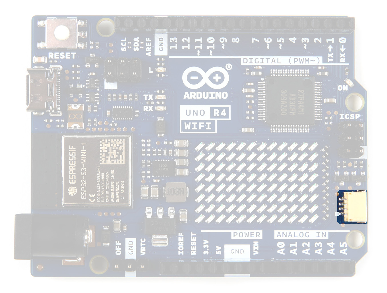
Qwiic Connector
The UNO R4 WiFi includes an industry-standard Qwiic I2C connector that facilitates quick prototyping. With a wide variety of compatible modules that can be connected over I2C, makers can easily create custom projects and expand the capabilities of the UNO R4 WiFi.
GPIO
The board features 14 digital I/O ports, 6 analog channels, dedicated pins for I2C, SPI and UART connections. The pins on either side of the board are highlighted here.
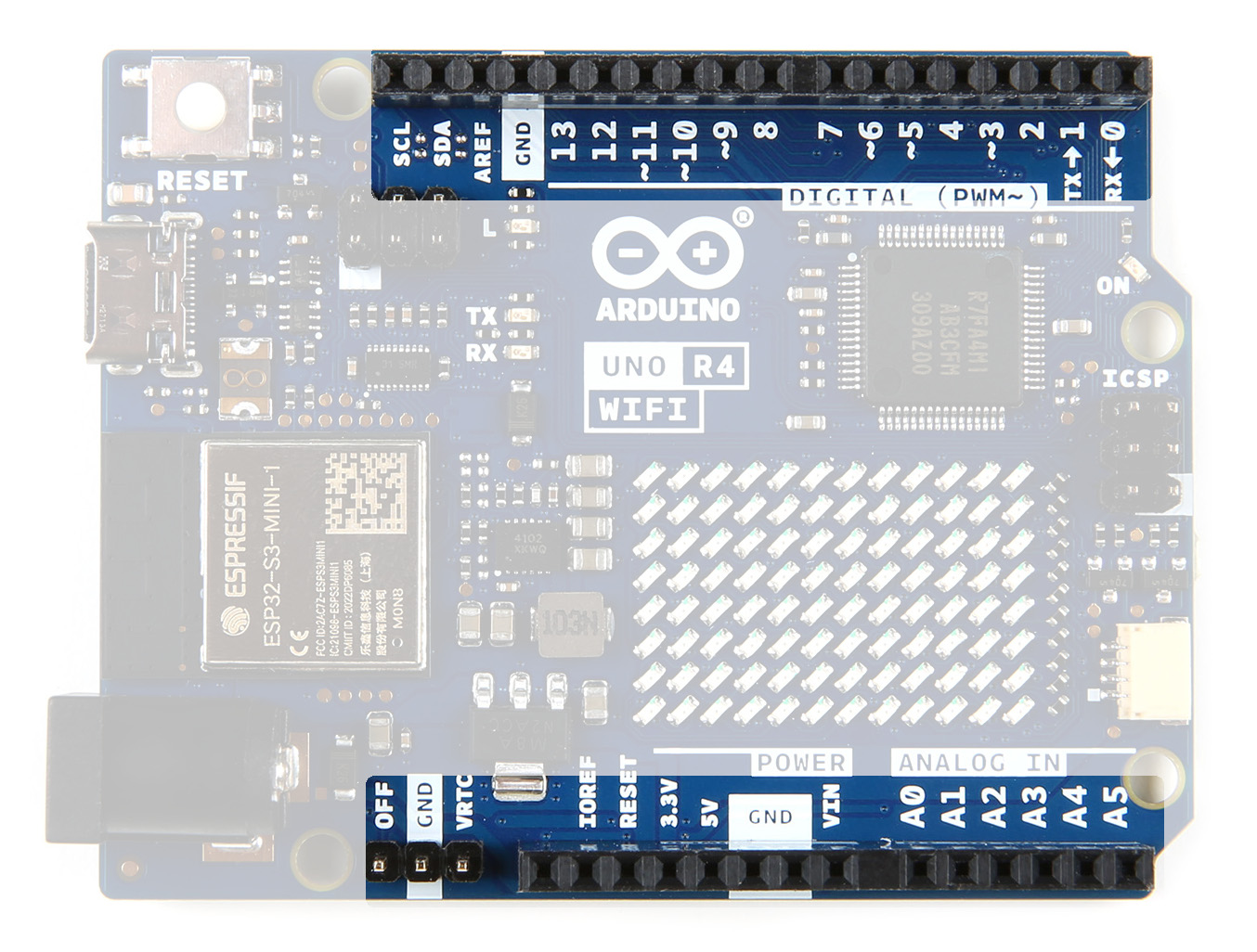
Their functionality is shown below; for more details, refer to the Product Reference Manual.
Installing Arduino
The following steps are a basic overview of getting started with the Arduino IDE. For more detailed, step-by-step instructions for setting up the Arduino IDE on your computer, please check out the following tutorial.
Installing Arduino IDE
Download the Arduino IDE
In order to get your microcontroller up and running, you'll need to download the newest version of the Arduino software first (it's free and open source!).
This software, known as the Arduino IDE, will allow you to program the board to do exactly what you want. It’s like a word processor for writing code.
Connecting the Arduino UNO R4 WiFi
Use the USB cable provided in the kit to connect the Arduino UNO R4 to one of your computer’s USB inputs.
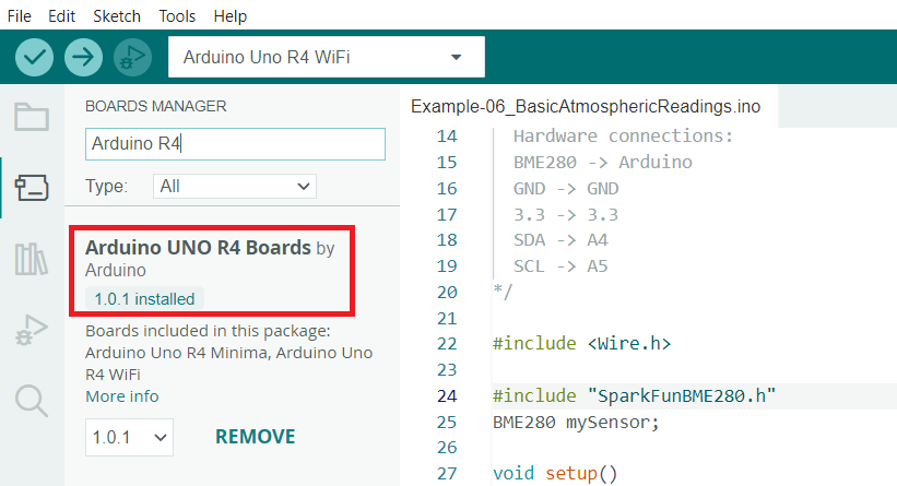
Install the Arduino Uno R4 Board Definition
If you haven't already done so, make sure you have the Board Definitions installed for the Arduino Uno R4 boards. Go up to the Tools menu, hover over Board, and select Boards Manager. Type in Arduino R4, and you should see the following. Click Install to install the board defs.
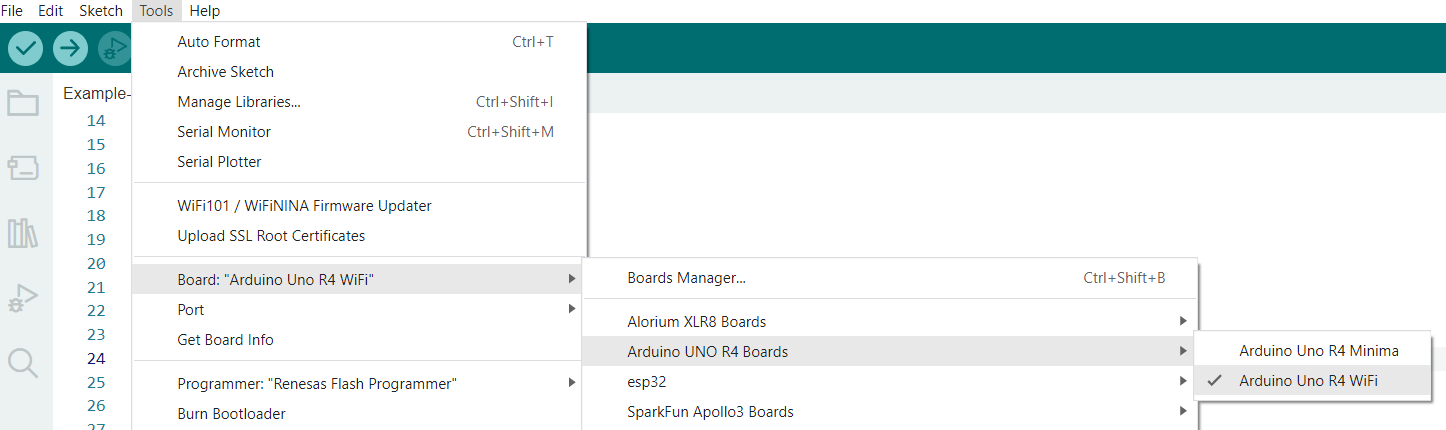
Select Your Board: Arduino Uno R4
Before we can start jumping into the experiments, there are a couple adjustments we need to make. This step is required to tell the Arduino IDE which of the many Arduino boards we have. Go up to the Tools menu. Then hover over Board and subsequently the Arduino UNO R4 Boards menus, and make sure Arduino Uno R4 WiFi is selected.
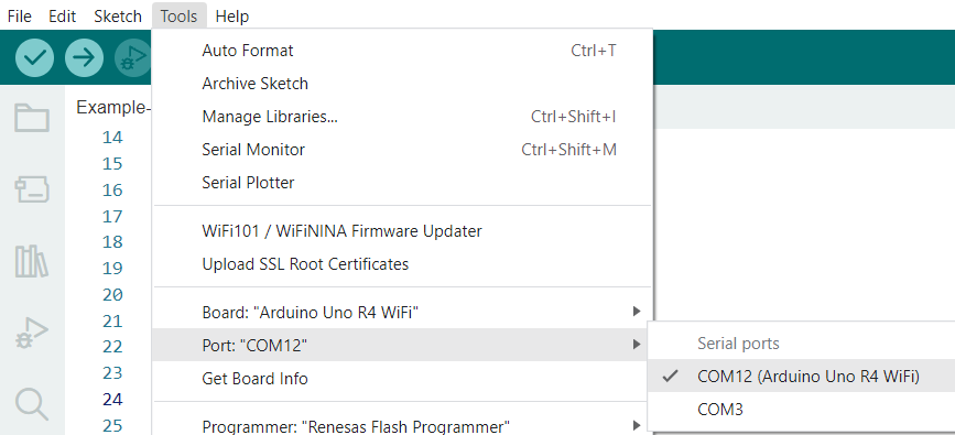
Select a Serial Port
Next up we need to tell the Arduino IDE which of our computer's serial ports the microcontroller is connected to. For this, again go up to Tools, then hover over Port and select your Arduino Uno R4 WiFi's serial port.
Software
We have compiled a set of examples to show how the basics work on this board. You can download the examples here:
These are just the ino files. Each of the examples requires a separate library to be installed. Each example in this guide will walk you through installing the required library. Let's get hacking!
Example 1: Qwiic LED Button
This first example shows how the Qwiic LED Button can be hooked up and programmed to pulse while pressed.
Library Installation
In order for this example to work, you'll need to also install the library for the SparkFun Qwiic Button. The easiest way to install this library is to search for SparkFun Qwiic Button in the Arduino Library Manager tool. You can also manually install the Qwiic Button Library from the GitHub Repository or you can download it by clicking the button below.
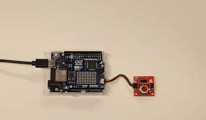
Hardware Hookup
Plug one end of the Qwiic connector into the Qwiic port on the breakout board, and the other end into the Qwiic connector on the Arduino Uno R4 WiFi board like so:
Software Example - Pulse When Pressed
The following example is taken from Example 3 of the SparkFun Qwiic Button library and is titled "Pulse When Pressed". The code connects the Qwiic Button to the I2C bus and runs the Button LED through a configured sequence when the button is pressed. The code configures the LED settings for brightness, cycleTime and offTime to pulse the Button LED while it is pressed. Try playing around with these settings to change the behavior of the LED.
language:c
/******************************************************************************
  Checks whether the button is pressed, and light it up if it is! Also prints
  status to the serial monitor.

  Fischer Moseley @ SparkFun Electronics
  Original Creation Date: July 24, 2019

  This code is Lemonadeware; if you see me (or any other SparkFun employee) at the
  local, and you've found our code helpful, please buy us a round!

  Hardware Connections:
  Attach the Qwiic Shield to your Arduino/Photon/ESP32 or other
  Plug the button into the shield
  Print it to the serial monitor at 115200 baud.

  Distributed as-is; no warranty is given.
******************************************************************************/

#include <SparkFun_Qwiic_Button.h>
QwiicButton button;
//Define LED characteristics
uint8_t brightness = 250;   //The maximum brightness of the pulsing LED. Can be between 0 (min) and 255 (max)
uint16_t cycleTime = 1000;   //The total time for the pulse to take. Set to a bigger number for a slower pulse, or a smaller number for a faster pulse
uint16_t offTime = 200;     //The total time to stay off between pulses. Set to 0 to be pulsing continuously.

void setup() {
  Serial.begin(115200);
  Serial.println("Qwiic button examples");
  Wire1.begin(); //Join I2C bus

  //check if button will acknowledge over I2C
  if (button.begin(SFE_QWIIC_BUTTON_DEFAULT_ADDRESS, Wire1) == false) {
    Serial.println("Device did not acknowledge! Freezing.");
    while (1);
  }
  Serial.println("Button acknowledged.");
  button.LEDoff();  //start with the LED off
}

void loop() {
  //check if button is pressed, and tell us if it is!
  if (button.isPressed() == true) {
    Serial.println("The button is pressed!");
    button.LEDconfig(brightness, cycleTime, offTime);
    while (button.isPressed() == true)
      delay(10);  //wait for user to stop pressing
    Serial.println("The button is not pressed.");
    button.LEDoff();
  }
  delay(20); //let's not hammer too hard on the I2C bus
}
Notice that the code uses Wire1. The Qwiic connector on the Arduino UNO R4 WiFi Board is connected to a secondary I2C bus on this board, IIC0. This connector is 3.3V only, connecting higher voltages may damage your board. To initialize this bus, use Wire1.begin() instead.
You should have the correct board and port selected, as per the Software section of this guide. Upload the code, and when you press the button you should see the button pulse as below:
Example 2: Qwiic Twist
Library Installation
We’ve written an easy to use Arduino library that covers the gamut of features on the Qwiic Twist. The easiest way to install the library is by searching SparkFun Twist within the Arduino library manager. We’ve even got a tutorial on installing an Arduino library if you need it. You can also manually install the Qwiic Twist library by downloading a zip:
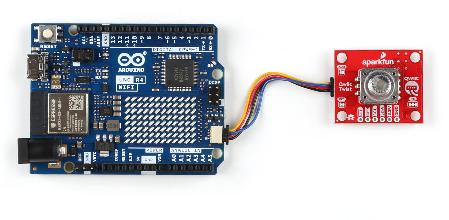
Hardware Hookup
Plug one end of the Qwiic connector into the Qwiic port on the breakout board, and the other end into the Qwiic connector on the Arduino Uno R4 WiFi board like so:
Software Example - Basic Readings
This example is a basic one from the SparkFun Twist Library and just prints the number of times the knob has been turned to the serial output.
language:c
/*
  Read and interact with the SparkFun Qwiic Twist digital RGB encoder
  By: Nathan Seidle
  SparkFun Electronics
  Date: December 3rd, 2018
  License: MIT. See license file for more information but you can
  basically do whatever you want with this code.

  This example prints the number of steps the encoder has been twisted.

  Feel like supporting open source hardware?
  Buy a board from SparkFun! https://www.sparkfun.com/products/15083

  Hardware Connections:
  Plug a Qwiic cable into the Qwiic Twist and a BlackBoard
  If you don't have a platform with a Qwiic connection use the SparkFun Qwiic Breadboard Jumper (https://www.sparkfun.com/products/14425)
  Open the serial monitor at 115200 baud to see the output
*/

#include "SparkFun_Qwiic_Twist_Arduino_Library.h" //Click here to get the library: http://librarymanager/All#SparkFun_Twist
TWIST twist;                                      //Create instance of this object

void setup()
{
  Serial.begin(115200);
  Serial.println("Qwiic Twist Example");

  if (twist.begin(Wire1) == false)
  {
    Serial.println("Twist does not appear to be connected. Please check wiring. Freezing...");
    while (1)
      ;
  }
}

void loop()
{
  Serial.print("Count: ");
  Serial.print(twist.getCount());

  if (twist.isPressed())
    Serial.print(" Pressed!");

  Serial.println();

  delay(10);
}
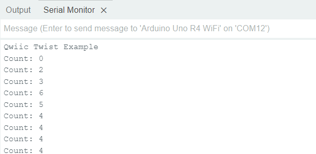
As before, you should have the correct board and port selected in the Tools menu. Go ahead and upload the code, and open a Serial Monitor. You should see something like the below:
Example 3: Qwiic OLED
Library Installation
The easiest way to install the Qwiic OLED library is to search for SparkFun Qwiic OLED in the Arduino Library Manager tool. You can also manually install the Qwiic OLED Library from the SparkFun Qwiic OLED Arduino GitHub Repository. Alternatively, you can download by clicking the button below.
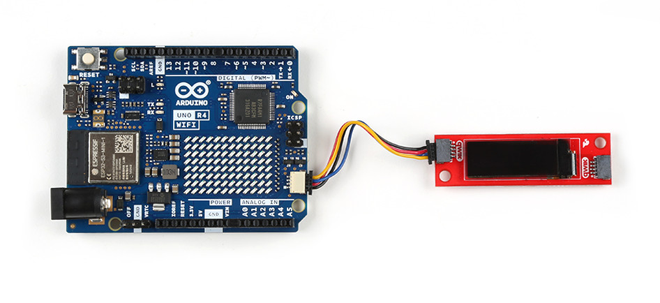
Hardware Hookup
Plug one end of the Qwiic connector into the Qwiic port on the breakout board, and the other end into the Qwiic connector on the Arduino Uno R4 WiFi board like so:
Software Example
The following example is taken from Example 1 of the SparkFun Qwiic OLED library and is titled "Hello".
language:c
/*

  Example-01_Hello.ino

  This demo shows the basic setup of the OLED library, generating simple graphics and displaying
  the results on the target device.

   Micro OLED             https://www.sparkfun.com/products/14532
   Transparent OLED       https://www.sparkfun.com/products/15173
   "Narrow" OLED          https://www.sparkfun.com/products/17153

  Written by Kirk Benell @ SparkFun Electronics, March 2022

  Repository:
     https://github.com/sparkfun/SparkFun_Qwiic_OLED_Arduino_Library

  Documentation:
     https://sparkfun.github.io/SparkFun_Qwiic_OLED_Arduino_Library/

  SparkFun code, firmware, and software is released under the MIT License(http://opensource.org/licenses/MIT).
*/

#include <SparkFun_Qwiic_OLED.h> //http://librarymanager/All#SparkFun_Qwiic_Graphic_OLED

// The Library supports three different types of SparkFun boards. The demo uses the following
// defines to determine which device is being used. Uncomment the device being used for this demo.

// QwiicMicroOLED myOLED;
// QwiicTransparentOLED myOLED;
QwiicNarrowOLED myOLED;


void setup()
{
    Serial.begin(115200);
    Serial.println("Running OLED example");

    Wire1.begin();

    // Initalize the OLED device and related graphics system
    if (myOLED.begin(Wire1) == false)
    {
        Serial.println("Device begin failed. Freezing...");
        while (true)
            ;
    }
    Serial.println("Begin success");

    // Do a simple test - fill a rectangle on the screen and then print hello!

    // Fill a rectangle on the screen that has a 4 pixel board
    myOLED.rectangleFill(4, 4, myOLED.getWidth() - 8, myOLED.getHeight() - 8);

    String hello = "hello"; // our message

    // Center our message on the screen. Get the screen size of the "hello" string,
    // calling the getStringWidth() and getStringHeight() methods on the oled

    // starting x position - screen width minus string width  / 2
    int x0 = (myOLED.getWidth() - myOLED.getStringWidth(hello)) / 2;

    // starting y position - screen height minus string height / 2
    int y0 = (myOLED.getHeight() - myOLED.getStringHeight(hello)) / 2;

    // Draw the text - color of black (0)
    myOLED.text(x0, y0, hello, 0);

    // There's nothing on the screen yet - Now send the graphics to the device
    myOLED.display();

    // That's it - HELLO!
}

void loop()
{
    delay(1000); // Do nothing
}
As before, make sure you select the correct board and port in the tools menu. Upload the code, and you should see something like the image below.

Play with the settings, make your OLED say different things!
Example 4: Qwiic Ambient Light Sensor (VEML6030)
Library Installation
The Qwiic Ambient Light Sensor (VEML6030) library will give you the full functionality of the sensor and provides example code to get the most our of your project. You can obtain these libraries through the Arduino Library Manager by searching SparkFun Ambient Light Sensor. The second option is to download the ZIP file below from its GitHub repository to manually install.
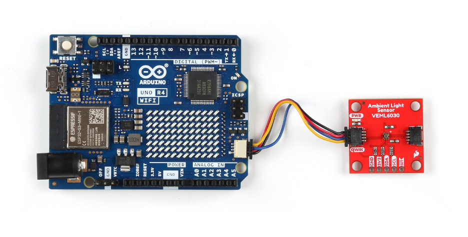
Hardware Hookup
Plug one end of the Qwiic connector into the Qwiic port on the breakout board, and the other end into the Qwiic connector on the Arduino Uno R4 WiFi board like so:
Software Example
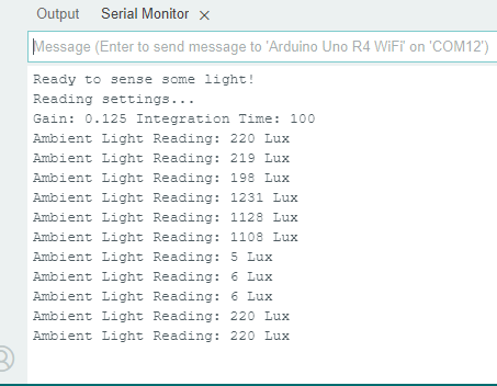
In this example, we'll get you comfortable with gathering ambient light and setting two vital properties of the sensor's ability to read light: the gain and the integration time. These two properties determine the resolution (accuracy) of the reading and the available ranges of light that you can read! For example, a gain of 1/8 and 800ms integration time cannot read anything above 3775 Lux. This means you'll max out your sensor outdoors but would be a proper setting for dim rooms due to it's higher resolution.
language:c
/*
  This example code will walk you through how to read ambient light values.
  Chances are good that you'll use this sensor in various environments so it'll
  also walk you through setting the gain and integration time that allow for
  different ranges of lux values. For example using the default gain of 100ms
  gives you a maximum reading of 30,199 Lux. This is great for daylight
  readings but not DIRECT sun. Higher integration times mean higher
  resoultions but lower lux values and vice versa: the lowest integration time
  and lowest gain should be used for mid day direct light. Check our hookup
  guide for more information.

  SparkFun Electronics
  Author: Elias Santistevan
  Date: July 2019

    License: This code is public domain but if you use this and we meet someday, get me a beer!

    Feel like supporting our work? Buy a board from Sparkfun!
    https://www.sparkfun.com/products/15436

*/

#include <Wire.h>
#include "SparkFun_VEML6030_Ambient_Light_Sensor.h"

#define AL_ADDR 0x48

SparkFun_Ambient_Light light(AL_ADDR);

// Possible values: .125, .25, 1, 2
// Both .125 and .25 should be used in most cases except darker rooms.
// A gain of 2 should only be used if the sensor will be covered by a dark
// glass.
float gain = .125;

// Possible integration times in milliseconds: 800, 400, 200, 100, 50, 25
// Higher times give higher resolutions and should be used in darker light.
int timeLength = 100;
long luxVal = 0;

void setup(){

  Wire1.begin();
  Serial.begin(115200);

  if(light.begin(Wire1))
    Serial.println("Ready to sense some light!");
  else
    Serial.println("Could not communicate with the sensor!");

  // Again the gain and integration times determine the resolution of the lux
  // value, and give different ranges of possible light readings. Check out
  // hoookup guide for more info.
  light.setGain(gain);
  light.setIntegTime(timeLength);

  Serial.println("Reading settings...");
  Serial.print("Gain: ");
  float gainVal = light.readGain();
  Serial.print(gainVal, 3);
  Serial.print(" Integration Time: ");
  int timeVal = light.readIntegTime();
  Serial.println(timeVal);

}

void loop(){

  luxVal = light.readLight();
  Serial.print("Ambient Light Reading: ");
  Serial.print(luxVal);
  Serial.println(" Lux");
  delay(1000);

}
Make sure you have the correct board and port selected, and upload the code. Open a Serial Monitor and you should see something like the below:
Example 5: Triple Axis Accelerometer Breakout - BMA400 (Qwiic)
Library Installation
The SparkFun BMA400 Arduino Library is based off the API for the sensor from Bosch to let users get started reading data from the sensor and using the various interrupt options. Install the library through the Arduino Library Manager tool by searching for "SparkFun BMA400". Users who prefer to manually install the library can download a copy of it from the GitHub repository by clicking the button below:
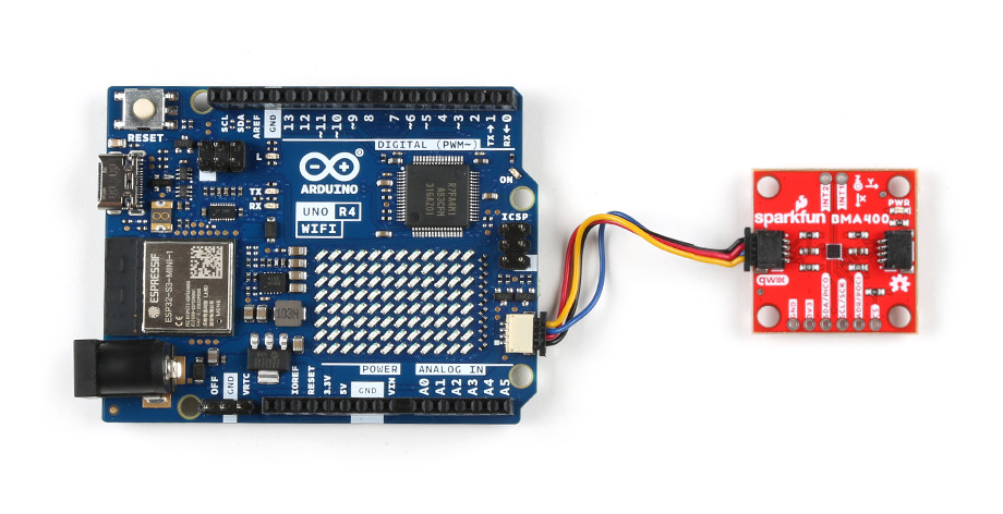
Hardware Hookup
Plug one end of the Qwiic connector into the Qwiic port on the breakout board, and the other end into the Qwiic connector on the Arduino Uno R4 WiFi board like so:
Software Example
This example demonstrates how to set the BMA400 up to communicate basic motion data over I2C.
language:c
#include <Wire.h>
#include "SparkFun_BMA400_Arduino_Library.h"

// Create a new sensor object
BMA400 accelerometer;

// I2C address selection
uint8_t i2cAddress = BMA400_I2C_ADDRESS_DEFAULT; // 0x14
//uint8_t i2cAddress = BMA400_I2C_ADDRESS_SECONDARY; // 0x15

void setup()
{
    // Start serial
    Serial.begin(115200);
    Serial.println("BMA400 Example 1 - Basic Readings I2C");

    // Initialize the I2C library
    Wire1.begin();

    // Check if sensor is connected and initialize
    // Address is optional (defaults to 0x14)
    while(accelerometer.beginI2C(i2cAddress, Wire1) != BMA400_OK)
    {
        // Not connected, inform user
        Serial.println("Error: BMA400 not connected, check wiring and I2C address!");

        // Wait a bit to see if connection is established
        delay(1000);
    }

    Serial.println("BMA400 connected!");
}

void loop()
{
    // Get measurements from the sensor. This must be called before accessing
    // the acceleration data, otherwise it will never update
    accelerometer.getSensorData();

    // Print acceleration data
    Serial.print("Acceleration in g's");
    Serial.print("\t");
    Serial.print("X: ");
    Serial.print(accelerometer.data.accelX, 3);
    Serial.print("\t");
    Serial.print("Y: ");
    Serial.print(accelerometer.data.accelY, 3);
    Serial.print("\t");
    Serial.print("Z: ");
    Serial.println(accelerometer.data.accelZ, 3);

    // Pause
    delay(2000);
}
Select your Board and Port and click Upload. Open the serial monitor after the upload completes with the baud set to 115200 to watch motion data print out.
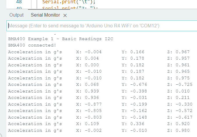
Move the sensor around in different directions and watch the acceleration data change with the motion.
Example 6: Qwiic Atmospheric Sensor (BME280)
Library Installation
We've written a library to easily get setup and take readings from the Qwiic Atmospheric Sensor, which you can install through the Arduino Library Manager. Search for SparkFun BME280 Arduino Library and you should be able to install the latest version. If you prefer manually downloading the libray from the GitHub repository, you can grab it here:
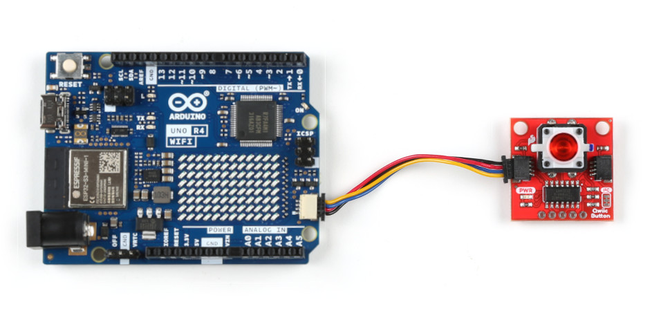
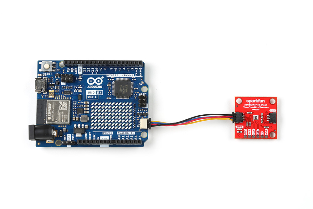
Hardware Hookup
Plug one end of the Qwiic connector into the Qwiic port on the breakout board, and the other end into the Qwiic connector on the Arduino Uno R4 WiFi board like so:
Software Example
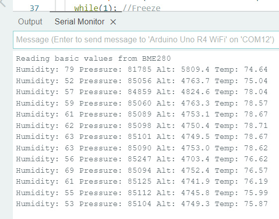
This basic example configures an BME280 on the I2C bus and reports out the data to the Serial Monitor at a baud rate of 115200 baud.
language:c
/*
  Get basic environmental readings from the BME280
  By: Nathan Seidle
  SparkFun Electronics
  Date: March 9th, 2018
  License: This code is public domain but you buy me a beer if you use this and we meet someday (Beerware license).

  Feel like supporting our work? Buy a board from SparkFun!
  https://www.sparkfun.com/products/14348 - Qwiic Combo Board
  https://www.sparkfun.com/products/13676 - BME280 Breakout Board

  This example shows how to read humidity, pressure, and current temperature from the BME280 over I2C.

  Hardware connections:
  BME280 -> Arduino
  GND -> GND
  3.3 -> 3.3
  SDA -> A4
  SCL -> A5
*/

#include <Wire.h>

#include "SparkFunBME280.h"
BME280 mySensor;

void setup()
{
  Serial.begin(115200);
  Serial.println("Reading basic values from BME280");

  Wire1.begin();

  if (mySensor.beginI2C(Wire1) == false) //Begin communication over I2C
  {
    Serial.println("The sensor did not respond. Please check wiring.");
    while(1); //Freeze
  }
}

void loop()
{
  Serial.print("Humidity: ");
  Serial.print(mySensor.readFloatHumidity(), 0);

  Serial.print(" Pressure: ");
  Serial.print(mySensor.readFloatPressure(), 0);

  Serial.print(" Alt: ");
  //Serial.print(mySensor.readFloatAltitudeMeters(), 1);
  Serial.print(mySensor.readFloatAltitudeFeet(), 1);

  Serial.print(" Temp: ");
  //Serial.print(mySensor.readTempC(), 2);
  Serial.print(mySensor.readTempF(), 2);

  Serial.println();

  delay(50);
}
Select your Board and Port and click Upload. Open the serial monitor after the upload completes with the baud set to 115200 to watch data print out.
Troubleshooting
If your product is not working as you expected or you need technical assistance or information, head on over to the SparkFun Technical Assistance page for some initial troubleshooting.
If you don't find what you need there, the SparkFun Forums are a great place to find and ask for help. If this is your first visit, you'll need to create a Forum Account to search product forums and post questions.
Resources and Going Further
This is a basic guide to get you started with your SparkFun Arduino UNO R4 WiFi Kit. For more information, check out the resources below:
Qwiic LED Button
- Schematic (PDF)
- Eagle Files (ZIP)
- Board Dimensions (PNG)
- Qwiic Button Arduino Library
- GitHub Hardware Repo
Qwiic Twist
- Schematic (PDF)
- Eagle (ZIP)
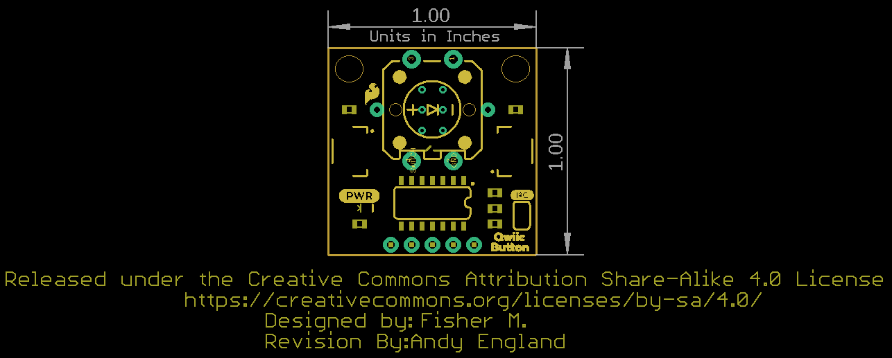
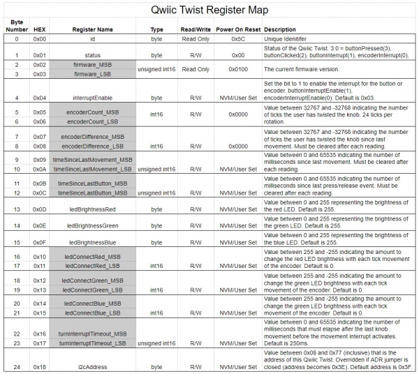
- Qwiic Twist Register Map
- SparkFun Qwiic Twist Arduino Library
- GitHub Hardware Repo - For Qwiic Twist that includes the firmware for the ATtiny84
Qwiic OLED
Qwiic Ambient Light Sensor (VEML6030)
- Schematic (PDF)
- Eagle Files (ZIP)
- Datasheet (PDF)
- SparkFun Ambient Light Sensor Arduino LIbrary
- GitHub Hardware Repo
Triple Axis Accelerometer Breakout - BMA400 (Qwiic)
- Schematic (PDF)
- Eagle Files (ZIP)
- Board Dimensions (PNG)
- Datasheet (BMA400)
- BMA400 Arduino Library
- GitHub Hardware Repo
Qwiic Atmospheric Sensor (BME280)
- Schematic (PDF)
- Eagle Files (ZIP)
- BME280 Datasheet
- SparkFun BME280 Arduino Library
- GitHub Hardware Repo
Need help getting started with Arduino and I2C? Check out these resources: