Simultaneous RFID Tag Reader Hookup Guide
 Nate
Nate 
Hardware Hookup
There are two main options for hooking up this board. Depending on how you plan to communicate with the board will change which method is recommended for you.
We recommend reviewing the through-hole soldering tutorial and how to work with wire if you are not familiar with basic soldering techniques.
Communicating via USB UART Serial
To communicate with a computer via USB Serial we recommend the Serial Basic or other USB UART boards. To connect, you will need to solder a 6-pin right angle header to the Serial port section of the SRTR.
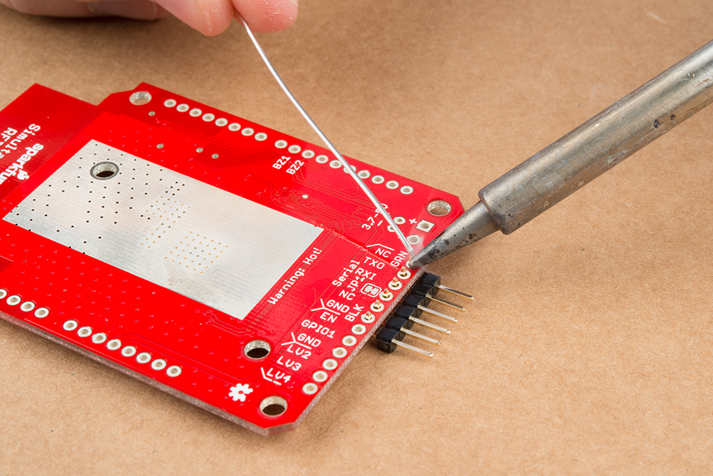
Plug in your serial breakout board via USB to your computer, and hook it up to the right angle headers that you just soldered to your SRTR.
Communicating via Arduino-Compatible Board
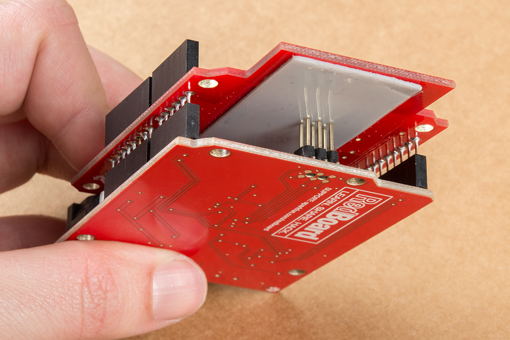
To use the SRTR as an Arduino shield, you will need solder stackable headers onto the shield. Check out our tutorial on soldering stackable headers if you are not sure how to do this.
We've used the SRTR with the RedBoard and other Uno compatible boards. Unfortunately the Leonardo and Mega don't support Softwareserial RX on pin 2 so you'll need to wire from pin 2 on the shield to pin D11. Additional pins will work for software RX but see the Softwareserial page for more information.
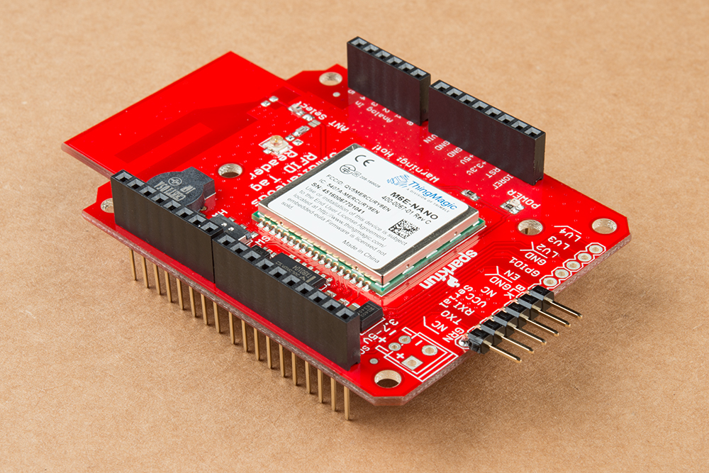

Next, install the shield onto the Arduino of your choice. We use the SparkFun RedBoard.