Simultaneous RFID Tag Reader Hookup Guide
 Nate
Nate Introduction
The SparkFun M6E Nano Simultaneous RFID Tag Reader (SRTR for short) has numerous features that make it a huge leap forward over other RFID readers.
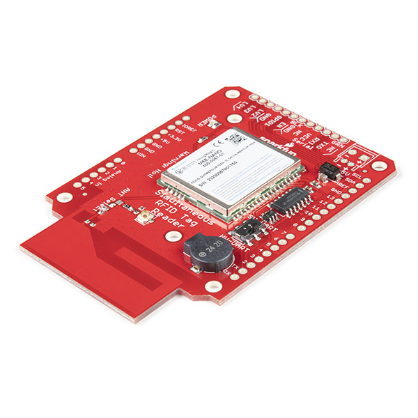
The greatest feature is that the SRTR is able to read multiple tags at the same time. Additionally the read distance of tags is greatly increased (up to 16 feet!) from other readers. Did we mention you can write your own data to the tags? Oh yea, you can do that too.
Suggested Materials
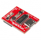
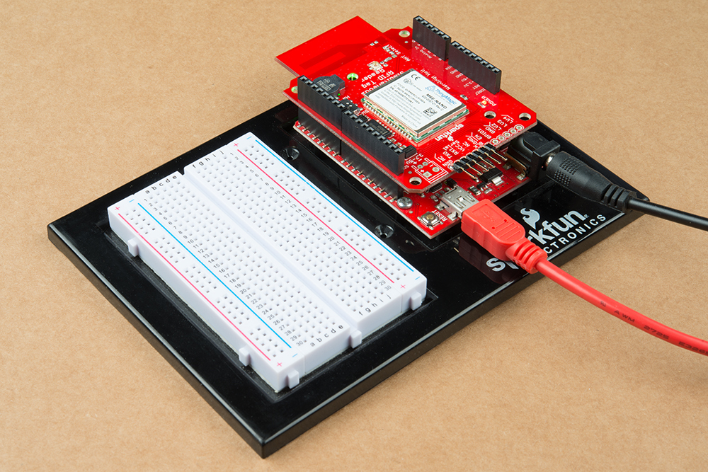
The SRTR was designed to work either with a USB to Serial connection to a computer or as a shield to an Arduino-compatible board. If you’re just getting started we recommend you start with the serial connection to a computer so that you can use the Universal Reader Assistant software to experiment quickly with different tags and read distances. Then move to a microcontroller or single board computer. You may not need everything though depending on what you have. Add it to your cart, read through the guide, and adjust the cart as necessary.
USB to Serial Connection
For a basic set-up using the SRTR with a USB-to-Serial connection, we recommend the following products.


Arduino Shield Connection
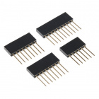
If you’re using the SRTR as a shield, we recommend the following materials.

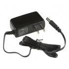
Any microcontroller or single board computer capable of 115200bps will work (however the module can be configured to 9600bps). The SparkFun RedBoard Qwiic or Arduino Uno are popular options for this role, but just about any microcontroller development board should work. (The firmware examples use an Arduino library, if that serves as any extra motivation to use an Arduino.) You will want an external power supply to run the module at full power. Please see the Power Supply Considerations section for more information.
Additional Materials
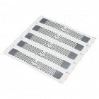
To follow along with the examples in this tutorial, you will also want access to some UHF passive RFID tags, and optionally, an antenna for extended range, and an attachment cable.
UHF RFID Tag (Set of 5)
WRL-14147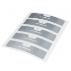
UHF RFID Tag - Adhesive (Set of 5)
WRL-14151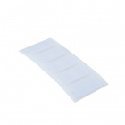
UHF RFID Tags - Adhesive (5 Pack)
WRL-20228Suggested Reading
If you aren't familiar with the following concepts, we recommend checking out these tutorials before continuing.
Serial Communication
Logic Levels
RFID Basics
Three Quick Tips About Using U.FL
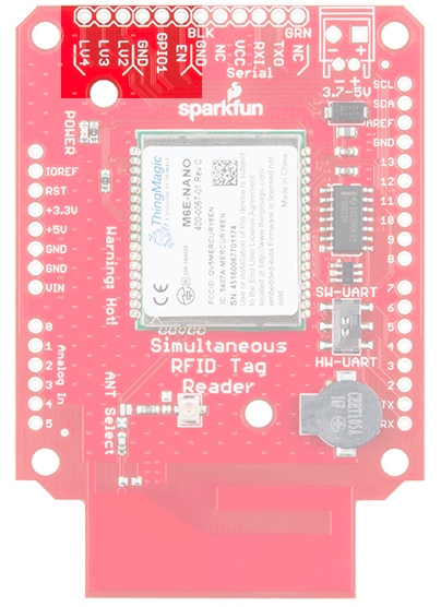
Hardware Overview
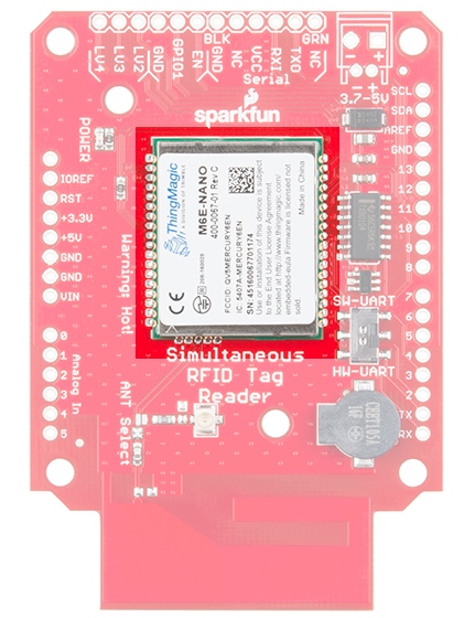
The main component of the SRTR is the M6E-NANO module from ThingMagic. ThingMagic has been in the multi-tag RFID business for years. Their newly release M6E-NANO module has reduced the cost of entry while maintaining many of the key features of multi-tag reading.
The M6E-NANO works with common, low cost, passive, Gen2 UHF tags available from a variety of online vendors in a variety of shapes and sizes. We offer two tags, with and without adhesive backing. Both have 64 bytes of user writable memory.
This module runs at 5V and pulls its power from the 5V lines on the breakout board.
Serial Interface
The M6E-NANO module is controlled via serial. There are two serial connections available: via a 6-pin FTDI compatible connection and via the TX/RX pins on the Arduino shield.
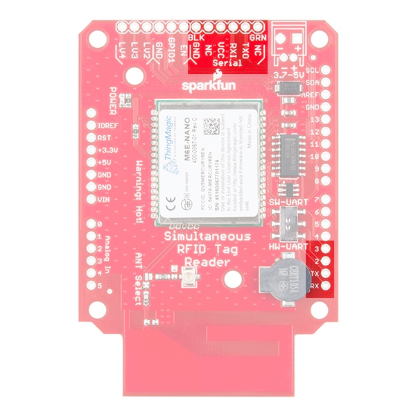
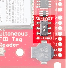
Serial Selection Switch
A switch is provided to allow the user to select between Hardware Serial (HW-UART) and Software serial (SW-UART) pins on the Arduino-compatible footprint. Set this switch to SW-UART for all the example Arduino sketches provided below. If you are using an external USB to Serial connection this switch has no effect.
Enable and GPIOs
The M6E uses an internal DC to DC converter to provide itself with power. When the EN (enable) pin is pulled low the DC/DC converter is turned off and the module does a hard reset. EN can be left unconnected for normal operation.
The NANO uses a SAMD21 as its main processor. The LV2, LV3, and LV4 pins are connected to the GPIOs on the SAMD21. They can be set high/low but these features are not yet supported in software.
Buzzer
A buzzer is connected to pins 9 and 10 and can be PWM controlled to produce a tone.
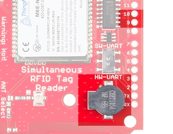
The most common use is to beep when a new tag is detected. This makes range testing much easier as you can bring the tag into the field until you hear a beep.
JP1
A jumper on the rear of the board labeled JP1 is closed by default allowing the board to be powered via the USB to Serial converter.

By default the JP1 Jumper is closed allowing the USB to Serial converter provide power to the SRTR. Cut this jumper if you are powering the board with a LiPo battery or other external power supply. This will isolate the USB to Serial converter for communication only.
Ground Plane Heatsink
The SRTR has a large ground plane heatsink on the bottom of the shield.
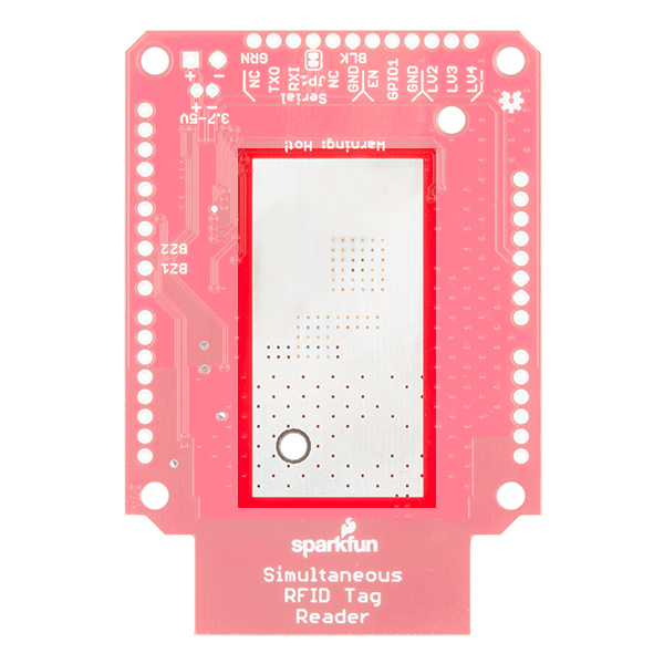
The exposed copper pour along with two mounting holes allow the connection to a heatsink such as a chassis or block of metal. Your board should have also shipped with a piece of Thermal Gap Filler. Please check out the Thermal Considerations section for more information on this.
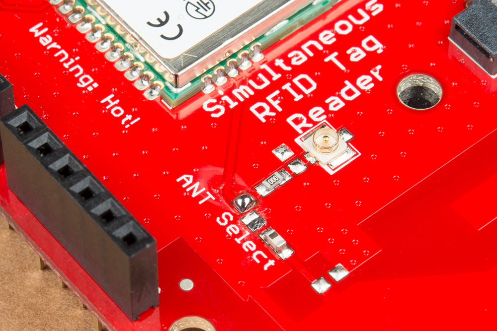
Antennas
The Nano M6E is a powerful transmitter capable of outputting up to 27dBm! That's a lot.
The SRTR comes with an on-board PCB trace antenna, and a u.FL connector for an external antenna. An ANT Select solder jumper allows users to select between the two options. Check the Using an External Antenna section for more information on this.
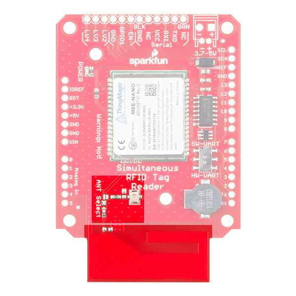
The PCB antenna is an excellent way to begin to experiment with UHF RFID. You’ll be able to read and write tags that are within 1 to 2 feet of the PCB. If you would prefer to use an external antenna, you can find more information in the Using an External Antenna section.
Hardware Hookup
There are two main options for hooking up this board. Depending on how you plan to communicate with the board will change which method is recommended for you.
We recommend reviewing the through-hole soldering tutorial and how to work with wire if you are not familiar with basic soldering techniques.
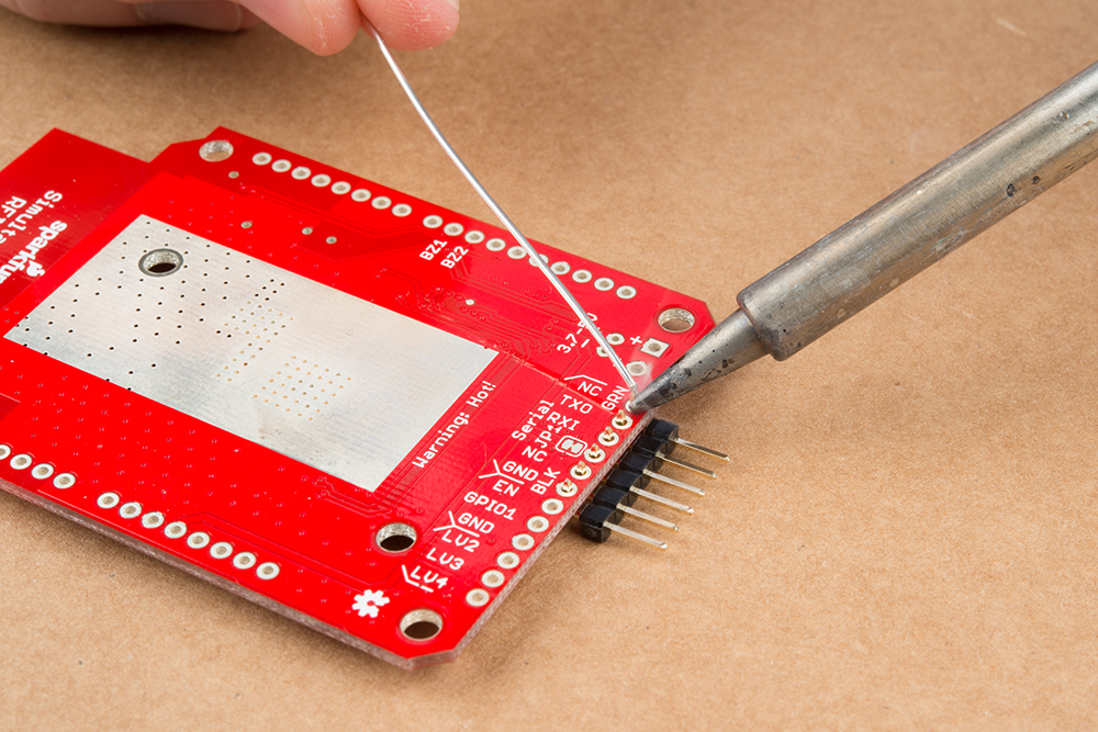
Communicating via USB UART Serial
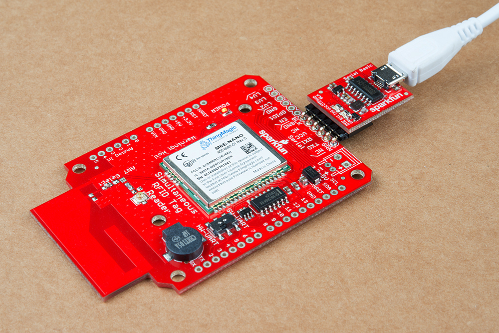
To communicate with a computer via USB Serial we recommend the Serial Basic or other USB UART boards. To connect, you will need to solder a 6-pin right angle header to the Serial port section of the SRTR.
Plug in your serial breakout board via USB to your computer, and hook it up to the right angle headers that you just soldered to your SRTR.
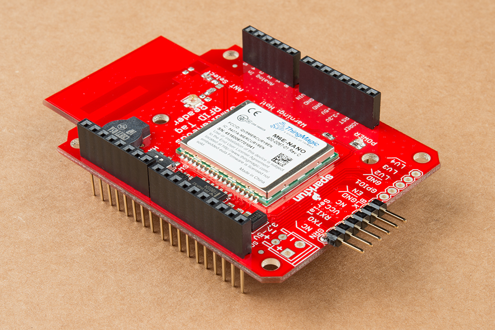
Communicating via Arduino-Compatible Board
To use the SRTR as an Arduino shield, you will need solder stackable headers onto the shield. Check out our tutorial on soldering stackable headers if you are not sure how to do this.
We've used the SRTR with the RedBoard and other Uno compatible boards. Unfortunately the Leonardo and Mega don't support Softwareserial RX on pin 2 so you'll need to wire from pin 2 on the shield to pin D11. Additional pins will work for software RX but see the Softwareserial page for more information.

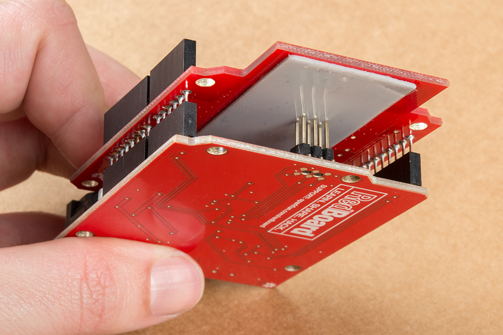
Next, install the shield onto the Arduino of your choice. We use the SparkFun RedBoard.
Using an External Antenna
Swapping from the PCB antenna to an external antenna can help with the range of your SRTR, but there are a few things to keep in mind before making that leap.
FCC Regulations
From page 42 of the Nano Design Guide:
No additional transmitter-compliance testing is required if the module is operated with the same type of antenna as listed in the FCC filing as long as it has equal or lower gain than the antenna listed. Equivalent antennas must be of the same general type (e.g. dipole, circularly polarized patch, etc.), must be of equal or less gain than an antenna previously authorized under the same FCC ID, and must have similar in band and out of band characteristics (consult specification sheet for cut-off frequencies).
The PCB trace antenna is a patch antenna with much lower gain than the list of approved antennas, therefore, the SRTR evaluation board as-is can be used in the field without additional FCC testing.
The u.FL connector is an easy way to connect higher gain directional antennas. However, there are stipulations as to what external antennas can be used and additional FCC certifications may be required.
Below is a list of antennas that ThingMagic has tested and gotten approved by the FCC. You may use a different antenna from the ones in the list but it must be of equal or less gain than an antenna previously authorized under the same FCC ID, and must have similar in band and out of band characteristics (consult specification sheet for cut-off frequencies) in order to use it in a product without additional testing.
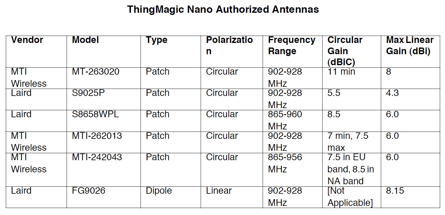
Attaching the External Antenna
If you want to switch from the onboard antenna, you will need to change the antenna jumpers around to enable the u.FL connector.
How to Work with Jumper Pads and PCB Traces
Using some solder wick, clear the solder jumper to the trace antenna and close the solder jumper to the u.FL connector by adding a blob of solder.
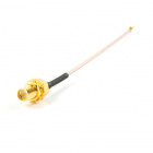
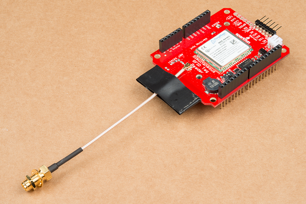
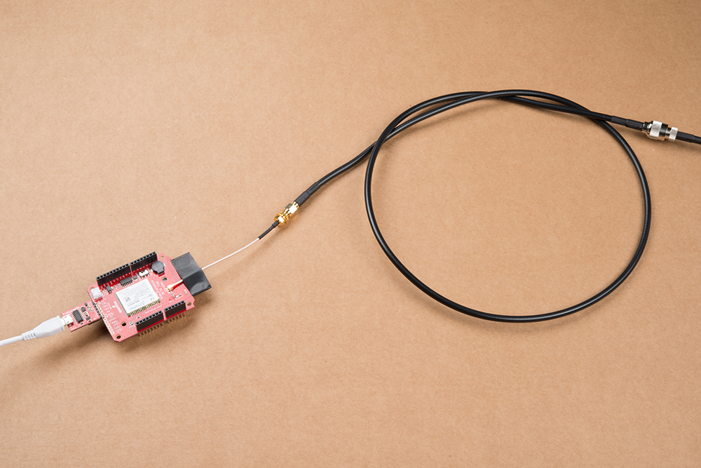
Next, attach the u.FL to the RP-SMA connector cable. Because this connector is fragile we recommend either taping or hot gluing the sheath of the cable to the PCB. This will help prevent damage to the u.FL connector in case the cable gets pulled on.
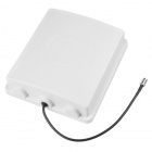
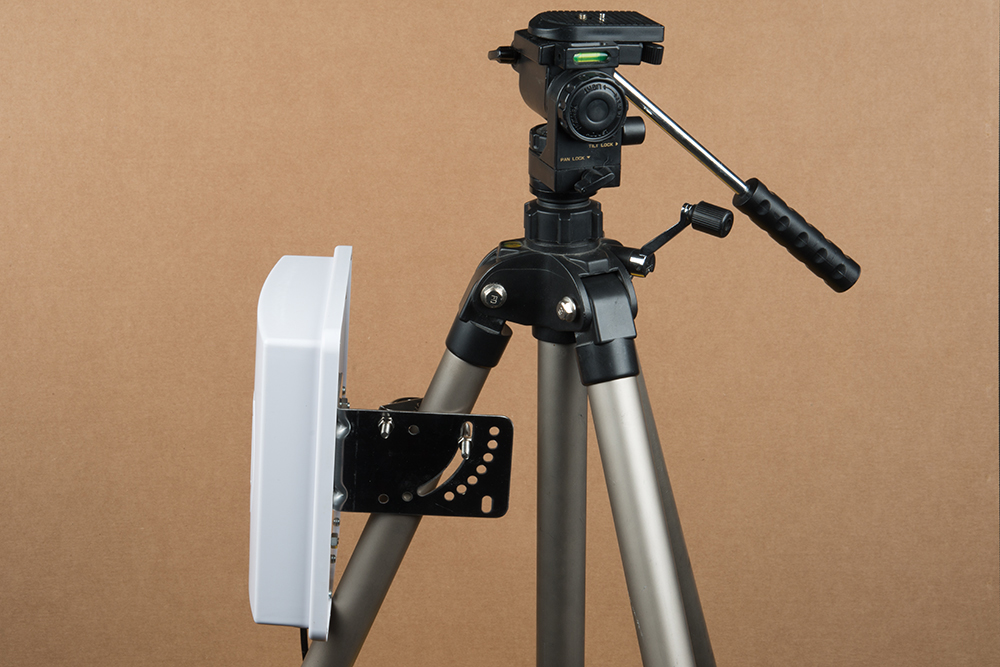
To get the best range we recommend attaching an external high-gain antenna to a tri-pod of some sort. If you only have a desk, that's ok too.
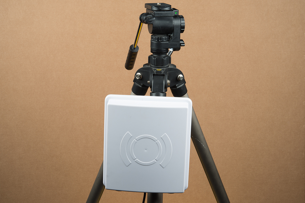
We used the included hardware with the antenna to attach it to a leg of the tripod.
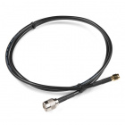
Now connect the RP-SMA to RP-TNC cable. And finally connect the RP-TNC to the external antenna. You can use a different UHF RFID antenna but you will need to have the correct connectors and cables to go from the u.FL connector on the PCB to the connector on your specific antenna.
Power Supply Considerations
The SRTR can be powered from the target board, the USB connection, or an external power supply.
USB Power (Good)
Standard USB ports will source up to 500mA. Because the Nano module can pull up to 720mA when powered from 5V the module will brown out and reset when operating at full read power. However, if read power is kept below 5dBm the SRTR can be evaluated using a simple USB-to-serial connection such as the FTDI Basic or Serial Basic.
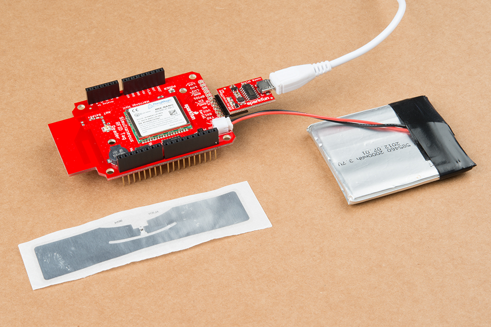
External/Battery Power (Better)
There is a footprint available to install a 2mm JST connector or a 3.5mm screw terminal. LiPos work well to power the module, however, if using a LiPo battery (3.7V nominal voltage) you can expect to use more than 1000mA during full read power. Pick your battery size accordingly. Alternatively, the 3.5mm screw terminal may be installed to connect to external power such as a bench power supply.
Target Power (Best)
Powering the SRTR over the 5V pin from an Arduino works well if the Arduino has an external power supply such as a 5V wall adapter. If the Arduino is powered only by USB the module will brown out under full read power. It's important to note that the shield gets its power from the 5V pin which means it's drawing power from the onboard regulator of whatever platform you are using. If you provide your RedBoard with 9V and draw 1A through the 5V regulator it will get red-hot. Use a 5V power adapter to reduce the thermal strain on your regulator.
Thermal Considerations
At full read power over extended periods of time the module can reach temperatures greater than 85C (185F). This is extremely toasty. The module will automatically throttle itself to prevent permanent damage from heat. The SparkFun Simultaneous RFID Tag Reader shield provides enough ground plane heatsinking to allow the module to operate at full read power for tens of minutes. If you plan to operate the module at full power for extended periods of time we recommend attaching a heatsink.
You can get the 1:1 dimensional drawing of the shield here. The dimensions of the exposed thermal and mounting holes are shown.
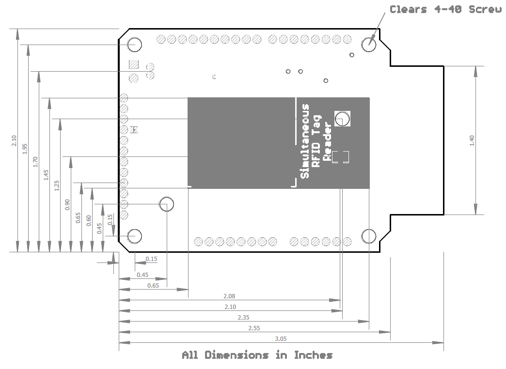
In most prototyping applications heatsinking won’t be required. However, if you have heat sensitive items near the module (such as temperature or humidity sensors) they may be influenced by the module. If you are planning to install the module for long term operation we recommend attaching a heatsink with thermal compound and 4-40 screws and nuts. Alternatively, you may install the Thermal Gap Filler that was shipped with your shield between the SRTR and the heatsink.
The module also supports changing read duty cycle to reduce the heat dissipation as well. Check out the M6E-NANO datasheet for more information.
Software Options
There are three ways of controlling the SRTR:
- We recommend starting with the software called Universal Reader Assistant (Windows only) with a USB to Serial connection.
- Arduino sketches to access the basic read/write features of the board. This is a complex device so we’ve included many example sketches to get you up and running with the main features. You'll get the example sketches when you download and install the library.
- Mercury API is ThingMagic’s extensive software libraries in C, Java, and .NET. This enables BeagleBones, Raspberry Pi’s, and other single board computers to get access to the full suite of features. The use of Mercury API is beyond the scope of this tutorial.
Using the Universal Reader Assistant
If you’re a Windows user the Universal Reader Assistant is a great way to get up and playing with the full capabilities of the M6E-NANO. The downside is that it’s only currently available for Windows.
Start by downloading the Universal Reader Assistant (URA). 32-bit and 64-bit versions are available.
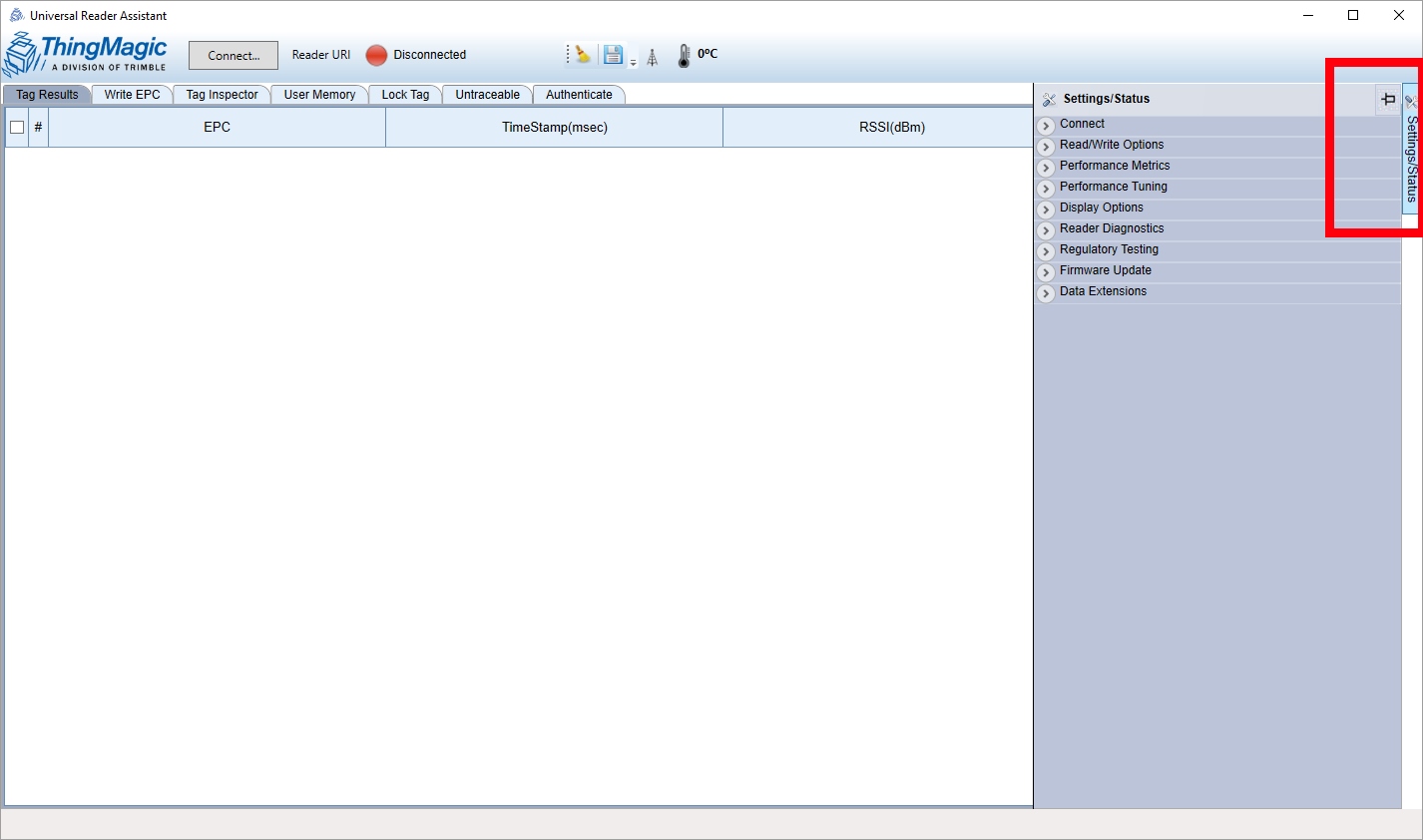
Once downloaded and installed, hover over the right side of the window. The Setting/Status control panel will open up. Click on the thumbtack icon to keep it open.
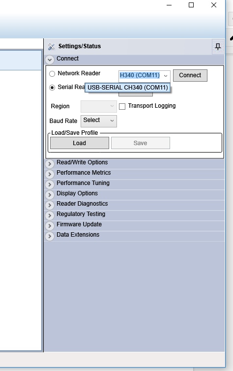
Expand the Connect menu and select Serial Reader and drop down the menu to select your COM port. Click Connect. The module will be pinged over the serial connection to verify its existence.
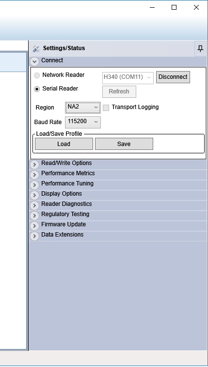
Next, select your Region. Since we are in North America, we've selected NA2.
Next open the Read/Write Options and click on 1 under Antennas.

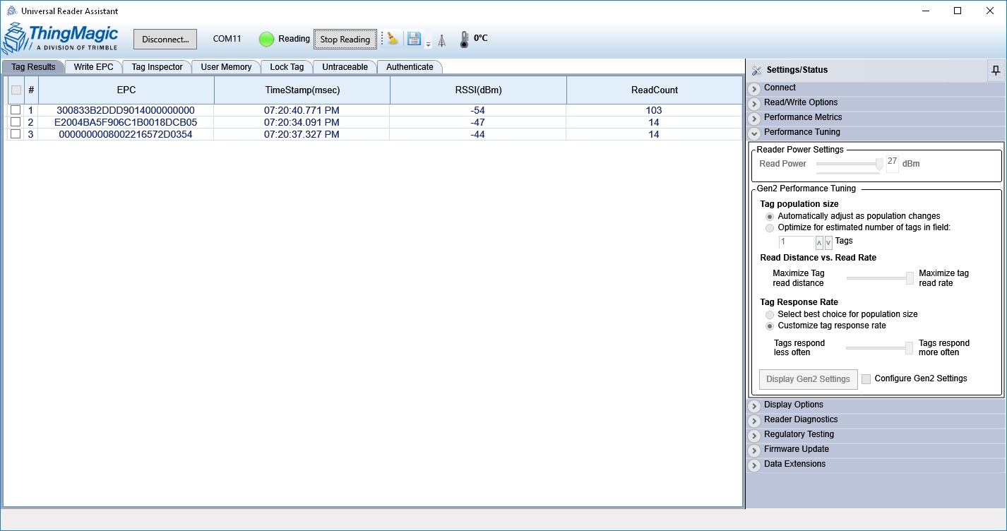
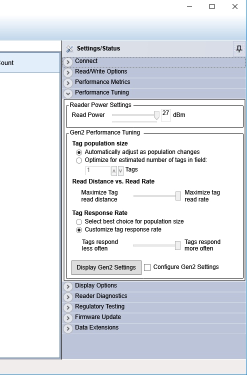
Finally, open the Reader Power Settings tab and select your Read Power. Tune this setting down to 5dBm. If you want to power the board from USB then use a power setting below 5dBm. 27dBm is ok to use only if you have external power (more than one USB port can provide). See the Power Supply Considerations section for more information.
Now we’re ready to read! Click on the Read button at the top. Bring some RFID tags near the reader and you'll see them appear.
There are a ton of features to the Nano from ThingMagic. Poke around the Universal Reader Assistant to learn more. Write EPC and User Memory are two of the most commonly used tabs.
Thermal Throttling: If you see this window pop up it means the module is reporting a temperature-limit fault condition.
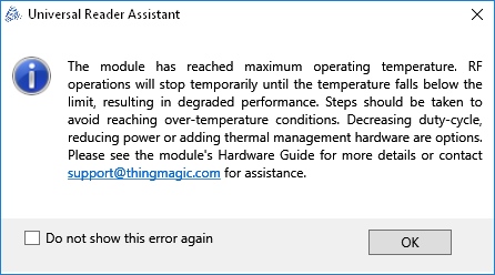
The module has an internal temperature sensor and will protect itself from permanent damage. You’ll need to lower your read power or add heatsinking. See the Thermal Considerations section for more information.
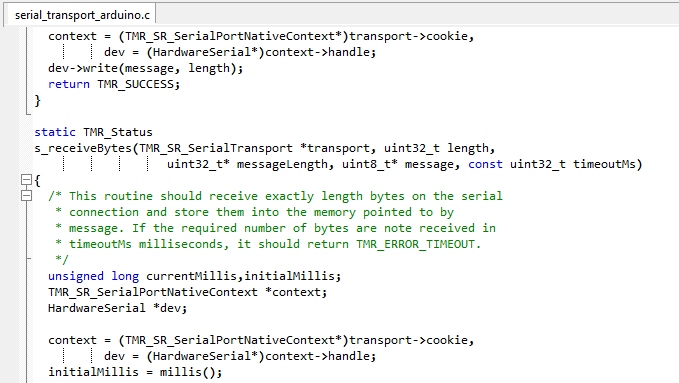
Using the Arduino Library
We've written an Arduino library for the M6E-NANO RFID module which takes care of all of the serial communication, byte manipulations, and CRC verifications.
Note: This example assumes you are using the latest version of the Arduino IDE on your desktop. If this is your first time using Arduino, please review our tutorial on installing the Arduino IDE.
The easiest way to install the library is through the Arduino Library manager by searching SparkFun RFID. If you have not previously installed an Arduino library, please check out our tutorial on installing an Arduino library.
You can also manually install the library with the following download from GitHub.
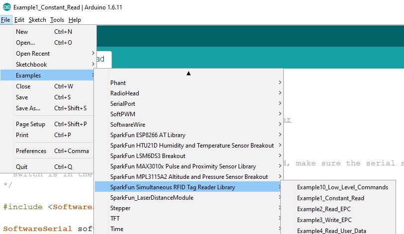
Once you’ve installed the library, you should see the Example sketches by navigating to File > Examples > SparkFun Simultaneous RFID Tag Reader Library > Examples.
Arduino Library Settings
The latest release of this library includes new definitions users should take note of before uploading and using the examples.
Serial Selection
When using this board with Software Serial uncomment the following lines and adjust the pins for RX/TX if necessary:
#include <SoftwareSerial.h>
SoftwareSerial softSerial(2, 3); //RX, TX
The next option selects which type of serial is used. The code lists a couple of examples for both software serial and hardware so adjust the definition as needed. For example, if you're using a software serial library, define this as softserial. If you're using a hardware serial port on your development board, select the serial port (eg. Serial1) as shown below:
// #define rfidSerial softSerial // Software serial (eg. Arudino Uno or SparkFun RedBoard)
#define rfidSerial Serial1 // Hardware serial (eg. ESP32 or Teensy)
Baud Rate Selection
Next, you'll want to define the baud rate for rfidBaud. We recommend using the settings shown below with 38400 when using software serial and 115200 when using hardware serial:
// #define rfidBaud 38400
#define rfidBaud 115200
Module Selection
Since this library supports both the M6E Nano and M7E Hecto, you'll need to define which module you are using. Adjust or comment/uncomment the moduleType definition to set it to the correct module:
// #define moduleType ThingMagic_M6E_NANO
#define moduleType ThingMagic_M7E_HECTO
Example 1 - Constant Read
Make sure you have set up your SRTR according to the directions in the Hardware Hookup section, and have installed your shield on an Arduino-compatible board.
Be sure the serial selection switch is set to Software. This connects pins 2/3 of the Arduino (for softSerial) to the serial port on the Nano, and allows the shield to work with the following Arduino examples.

Once you've got the shield attached and library installed, open the Example1 Constant Read sketch. You can find it under
File > Examples > SparkFun Simultaneous RFID Tag Reader Library > Examples
Then load it onto your RedBoard. Open your favorite Serial Terminal to see the printed values. The first example demonstrates how to scan constantly and report any tags in the vicinity.
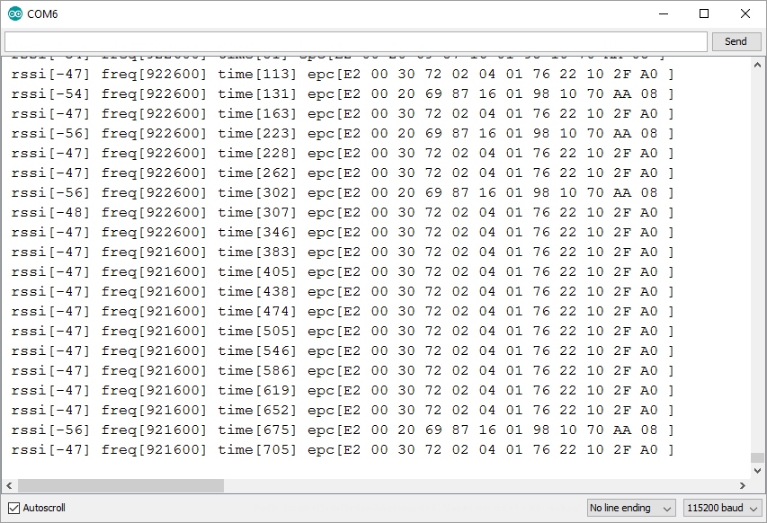
This example outputs the EPC from any tag in the vicinity. Note there are two different tags shown in this list.
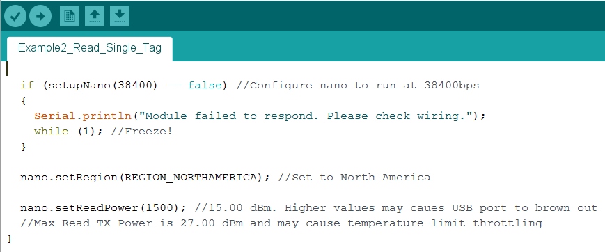
Let's look at the setup code:
if (setupNano(38400) == false) //Configure nano to run at 38400bps
{
  Serial.println(F("Module failed to respond. Please check wiring."));
  while (1); //Freeze!
}

nano.setRegion(REGION_NORTHAMERICA); //Set to North America

nano.setReadPower(1500); //15.00 dBm.
//Max Read TX Power is 27.00 dBm and may cause temperature-limit throttling

nano.startReading(); //Begin scanning for tags

Serial.println("Go!");
The Nano communicates over serial at 115200bps at power up. Because we are using software serial on pins 2/3 on the RedBoard we need to slow communication down to 38400bps. setupNano() is a local function that will tell the Nano to go to 38400bps and then verify that communication is open.
nano.setRegion(REGION_NORTHAMERICA); //Set to North America
Because different countries have different regulations for UHF RFID .setRegion() is used to configure the frequencies to operate within. Allowable regions are:
- REGION_INDIA
- REGION_JAPAN
- REGION_CHINA
- REGION_EUROPE
- REGION_KOREA
- REGION_AUSTRALIA
- REGION_NEWZEALAND
- REGION_NORTHAMERICA
- REGION_OPEN
Select the region closest to you or establish which regulations within your country match one of the available regions.
nano.setReadPower(500); //5.00 dBm. Higher values may caues USB port to brown out
//Max Read TX Power is 27.00 dBm and may cause temperature-limit throttling
The module is quite powerful and is capable of outputting 27dBm. By default we .setReadPower() to 5dBm so that the examples can be operated from a USB port without extra power. If you have a good power supply such as a LiPo battery or 2 amp wall supply you can increase the read power. See Power Supply Considerations and Thermal Considerations for more information about pushing the envelope.
nano.startReading(); //Begin scanning for tags
The .startReading() function tells the module to constantly scan for new tags and output any tag detected. Once a tag is detected the various bits of tag information (EPC, RSSI, etc) is parsed out of the response and printed.
Example 2 - Read EPC
While a constant read is fun and interactive, it can be an overwhelming amount of data for some projects. The 2nd example shows how to do a single shot read.
If you are unfamiliar with how RFID tag memories work, please review our tutorial here.
File > Examples > SparkFun Simultaneous RFID Tag Reader Library > Examples
Open Example 2 from the examples menu. Then load it onto your RedBoard or Uno.
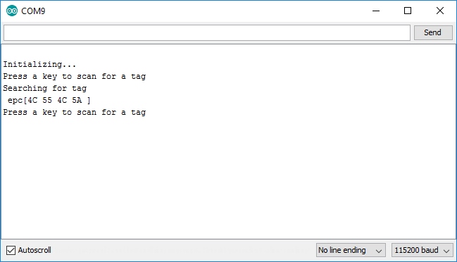
.readTagEPC() is the main function call of this example. Pass it an array of bytes (in almost all cases EPCs are 12 bytes), the size of the array (12), and an amount of time to scan before giving up (500ms is default). The function will return with RESPONSE_SUCCESS if a tag is detected and the EPC will be stored in the array you gave it.
responseType = nano.readTagEPC(myEPC, myEPClength, 500); //Scan for a new tag up to 500ms
//Beep! Piano keys to frequencies: http://www.sengpielaudio.com/KeyboardAndFrequencies.gif
tone(BUZZER1, 2093, 150); //C
delay(150);
tone(BUZZER1, 2349, 150); //D
delay(150);
tone(BUZZER1, 2637, 150); //E
delay(150);
We've included a buzzer on the shield to allow feedback to the user. In this example we play a simple three note melody to indicate a tag has been detected.
Example 3 - Write EPC
It's time to do what used to be impossible: Write to a tag!
Load Example 3 to your RedBoard, and open up your serial monitor.
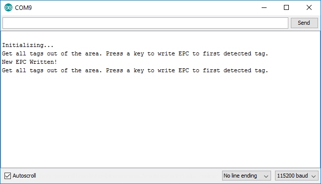
This example shows how to write your own EPC to a tag.
char stringEPC[] = "Hello!"; //You can only write even number of bytes
byte responseType = nano.writeTagEPC(stringEPC, sizeof(stringEPC) - 1); //The -1 shaves off the \0 found at the end of string
Remember, you cannot change the TID of a tag (that's its truly unique tag ID), but changing the EPC is a great way to keep track of which tag is which. Setting EPCs to WRENCH or PILL#317 make it easier to visually identify in code which tag you are looking for and need to respond to.
nano.setWritePower(500); //5.00 dBm. Higher values may cause USB port to brown out
//Max Write TX Power is 27.00 dBm and may cause temperature-limit throttling
This example introduces a new function .setWritePower(). Similar to setReadPower, this sets the power level when writing to a tag.
If you are using an external power supply and need to write to a tag feel free to boost this value to 20 or even 27dBm. Because you will rarely be writing to a tag the module shouldn't reach temperature throttling.
Example 4 - Read User Data
Example 4 shows how to detect and read the available user memory.

Note that not all UHF RFID tags have user memory, and therefore may not be configurable.
Example 5 - Write User Data
The User memory area is a fun place to play. A given UHF tag can have 0 to 64 bytes of editable User memory. Example 5 shows how to edit the User Data.
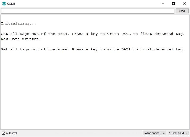
char testData[] = "ACBD"; //Must be even number of bytes. "Hello" is recorded as "Hell".
byte responseType = nano.writeUserData(testData, sizeof(testData) - 1); //The -1 shaves off the \0 found at the end of string
Give .writeUserData() an array of characters and it will be recorded to the first tag detected. A few bytes of editable memory may not sound like a lot be remember these are passive tags - no batteries required! You can query a tag for the user's dietary restrictions. Or you could adjust the lighting depending on who walked in the room. Or you could set the time at which a medication must be taken. Perhaps a prosthetic leg goes into a more aggressive mode when basketball shorts are worn. The applications get far reaching.
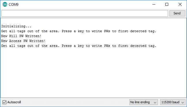
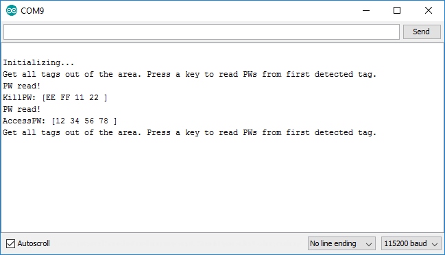
Examples 6, 7, 8 - Passwords
The Example6-Read Passwords example will display the Access and Kill passwords of a given tag. The Access password allows a user to lock a tag, preventing modification of various parts of the memory (EPC, User, etc). The Kill password is needed to disable a tag. Both passwords are 0x00000000 by default.

Example7-Write Passwords will show you how to write new passwords for the Access and Kill portions of memory.
To verify these new passwords have been written load Example6 again.
It may seem odd that you can view the passwords. The Gen2 protocol has quite a few methods to lock out various portions of the memory preventing them from being read. Once the Access password is set the ability to read passwords, read user memory, and read portions of the EPC can all be controlled; this is called locking. Currently, locking is not supported in the Arduino library but it is available in the URA and in the Mercury API.
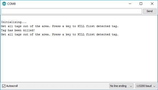
The final Example8-Kill Tag is the really fun one. It's pretty rare that you'll need to kill a tag but we find the concept fascinating and wanted to build in support for it.
Note: Killing a tag blows an internal fuse to the IC and makes the tag irreversibly dead.
It is very good to see that the protocol has the kill feature. Killing a tag makes sense after an item has been purchased (gallon of milk) or a process has been completed (dry cleaning has been picked up). By limiting the life-span of a tag you can help protect end user privacy and tracking.
The Gen2 protocol is well written and prevents a user from walking into a Wal-Mart and blasting away all the tags that haven't been configured. The default Kill password is all 0s but any tag will ignore the kill command with the password set to 0s. Therefore, you must first write a non-zero kill password (using Example7) then you must issue the kill command using the new password.
If you're very paranoid about someone else using an UHF RFID reader/writer to reconfigure your tags consider writing new Access and Kill passwords to your tags then use the Universal Reader Assistant to lock the tags.
Example 9 - Read TID
TIDs are the truly unique IDs assigned to each tag (and are not editable). They are 20 bytes long so they're a bit unwieldy but if you need them Example 9 will show you how.
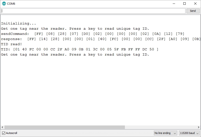
nano.enableDebugging(); //Turns on commands sent to and heard from RFID module
This example includes a new function called .enableDebugging(). This displays the commands sent to and responses from the RFID module. The counter function is .disableDebugging(). It's often helpful to see what commands are being sent to the module. Debugging also exposes how the module responded: Did it time out? Did it return an unknown response?
You can pass a port to .enableDebugging(). For example, nano.enableDebugging(Serial1); will enable and output debug messages to port Serial1. If you leave it blank debug messages will be piped to Serial by default.
When experimenting with features outside the scope of the Arduino library it is best to enable Transport Logging inside the URA to see what commands the URA is sending to the module. Within a new Arduino sketch send duplicates of the commands the URA is sending. The debug statements will help verify what you are sending and what was received.
Example 10 - Range Test
The PCB antenna on the shield will allow you to read tags up to around 24 inches at max read power (27dBm). If you really want to push the limit of read range you'll need an external antenna. With a good external antenna we've seen read distances of up to 16 feet (4.5 meters)!
Load Example10-Range Test onto your Arduino. As you bring a tag into range of the antenna you should hear a high pitched beep. When a tag is no longer detected you should hear a low pitched beep.
We are able to get more than 16 feet (4.5m) using the external antenna, with an external power supply (LiPo 1Ah battery), using SparkFun interface cables, and the URA software with the output power set to 27dBm. We didn't heat sink the module but it quickly approached 60C as we were testing over the course of 5 minutes.

This is a large image but if you open the image in a new tab and look closely you'll see the passive RFID tag hanging off the jaw of the T-Rex. Each carpet square is 2 feet and we were able to constantly read the tag more than 16 feet away! The NANO M6E is truly amazing.
But I'm not getting 16 feet!?
16 feet is really the best, most ideal situation. Our demonstration has no metal, no water, the tag is aligned with the antenna over open air and the power supply is as clean and powerful as possible (battery at 27dBm). Your real world results will vary greatly depending on many factors. It's best to get the hardware and test in the environment your application will be within.
Check out our troubleshooting recommendations for RFID systems here.
Tag Location
Can I tell where a tag is located? Can I use UHF RFID for location within a room?
The short answer is no. The reader emits a ‘bubble’ of energy and any tag within that bubble will be energized and report itself to the reader. You’ll know if a tag is in the bubble but you won’t be able to tell where it is within the bubble. If your reader is capable of reading tags from 16 feet away, that’s amazing, but that means you won’t know if the tag is 1 foot or 10 feet from the reader. There is a caveat: the reader reports the RSSI (basically signal strength) for each tag. This means you’ll be able to tell qualitatively which tag is closer to the reader (tag 1 has a stronger signal so it’s roughly closer to the read than tag 2) but you won’t be able to tell quantitatively (you cannot tell if tag 1 is 1.5 feet or 2 feet from the reader).
Resources and Going Further
For additional help with this project, please check out the following resources.
- M6E-NANO Design Guide- technical information about the module.
- EPC and RFID standards - set by GS1, the governing body behind RFID (and barcodes too!)
- RFID V2.0.1 Protocol
- ThingMagic App Note - Documentation for running the Mercury API on an Arduino Mega.
- SparkFun Simultaneous RFID Tag Reader Arduino Library Repository - Arduino Library files
- GitHub Hardware Repository - Hardware design files
- Eagle Files - .ZIP download of the schematic and board files
We hope you enjoyed reading this tutorial! Have fun with your RFID projects! If you need more inspiration, check out these other tutorials from SparkFun:
MicroPython Programming Tutorial: Getting Started with the ESP32 Thing
SparkFun Pro nRF52840 Mini Hookup Guide
nRF52840 Advanced Development With the nRF5 SDK
DA16200 Thing Plus Hookup Guide

Interested in more RFID?
We've got a page just for you! Get an overview of the basics of how RFID works, the hardware needed and tutorials to get you started.