Python Programming Tutorial: Getting Started with the Raspberry Pi
 Shawn Hymel
Experiment 3: SPI and Analog Input
Many sensors out there use an analog voltage to convey their measurement data. For example, photocells change their resistance depending on how much light is falling on the sensor. By using a voltage divider in our circuit, we can effectively measure the amount of ambient light by measuring a voltage.
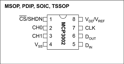
The bad news is that our Raspberry Pi does not come with any way to measure an analog voltage. To do that, we'll need to rely on a separate piece of circuitry: an analog-to-digital converter (ADC). Specifically, we'll be using the Microchip MCP3002, which is a niftly little chip that can measure up to 2 analog voltages on separate channels and report their values over the Serial Peripheral Interface (SPI) interface.
We'll use the built-in spidev module in Python to send commands and read replies on the SPI bus.
Recommended Reading
- Analog vs. Digital - What is the difference, and why do we need to care about them for this example?
- Voltage Dividers - Explains how to set up, use, and calculate the values in a voltage divider
- Serial Peripheral Interface (SPI) - Read this if you would like to learn how SPI works on a low level
- Binary - We'll be working directly in binary in this section
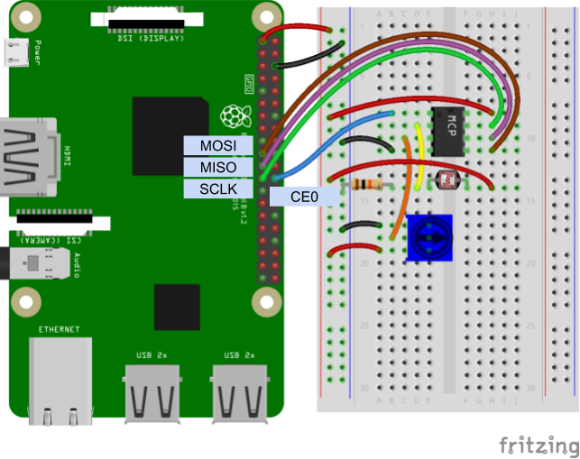
Hardware Connections
Refer to the Raspberry Pi Pinout section in the previous example if you would like to see what pins and GPIO labels belong to each of these connections.
- Connect MOSI (GPIO10, pin 19) to Din on the MCP3002
- Connect MISO (GPIO9, pin 21) to Dout on the MCP3002
- Connect SCLK (GPIO11, pin 23) to CLK on the MCP3002
- Connect CE0 (GPIO8, pin 24) to CS/SHDN on the MCP3002
- Connect the photocell voltage divider to CH0 on the MCP3002
- Connect the potentiometer's middle pin to CH1 on the MCP3002
- Make the power (3.3 V) and ground (GND) connections as shown in the Fritzing diagram
Connecting through a Pi Wedge:

Connecting directly to the Raspberry Pi:
Code: Reading Analog Voltage
Depending on your version of Raspbian, you may or may not have to install the spidev package (e.g. Raspbian Lite does not come with some Python packages pre-installed). In a terminal, enter the following:
language:bash
pip install spidev
In a new file, enter the following code:
language:python
import time
import spidev

spi_ch = 0

# Enable SPI
spi = spidev.SpiDev(0, spi_ch)
spi.max_speed_hz = 1200000

def read_adc(adc_ch, vref = 3.3):

    # Make sure ADC channel is 0 or 1
    if adc_ch != 0:
        adc_ch = 1

    # Construct SPI message
    #  First bit (Start): Logic high (1)
    #  Second bit (SGL/DIFF): 1 to select single mode
    #  Third bit (ODD/SIGN): Select channel (0 or 1)
    #  Fourth bit (MSFB): 0 for LSB first
    #  Next 12 bits: 0 (don't care)
    msg = 0b11
    msg = ((msg << 1) + adc_ch) << 5
    msg = [msg, 0b00000000]
    reply = spi.xfer2(msg)

    # Construct single integer out of the reply (2 bytes)
    adc = 0
    for n in reply:
        adc = (adc << 8) + n

    # Last bit (0) is not part of ADC value, shift to remove it
    adc = adc >> 1

    # Calculate voltage form ADC value
    voltage = (vref * adc) / 1024

    return voltage

# Report the channel 0 and channel 1 voltages to the terminal
try:
    while True:
        adc_0 = read_adc(0)
        adc_1 = read_adc(1)
        print("Ch 0:", round(adc_0, 2), "V Ch 1:", round(adc_1, 2), "V")
        time.sleep(0.2)

finally:
    spi.close()
    GPIO.cleanup()
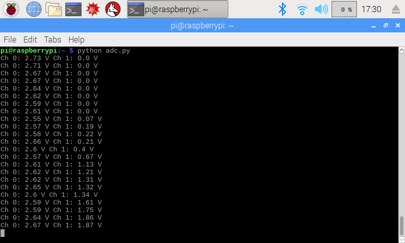
Save the file (e.g. adc.py), and run it with Python:
language:bash
python adc.py
You should be able to cover the photocell and see the Ch 0 voltage change. Adjust the knob on the potentiometer to see the Ch 1 voltage change.
Code to Note:
We are using SPI channel 0 on the Raspberry Pi when we initialize the SpiDev object:
language:python
spi_ch = 0
spi = spidev.SpiDev(0, spi_ch)
Channel 0 corresponds to using CE0 (chip enable 0) on the Pi's pins. If you wanted to use another device on the SPI bus, you would need to connect it to CE1 and use SpiDev channel 1 as well.
We construct our SPI message by manipulating individual bits. We start with binary 11 (which is the decimal number 3) by using the prefix '0b':
language:python
msg = 0b11
If you look at section 5 in the MCP3002 datasheet, you will see that we need to send a 1 to start transmission, followed by another 1 to denote that we want "single ended mode." After that, we select our channel with a 0 (for channel 0) or a 1 (for channel 1). Then, we send a 0 to show that we want data returned to us with the least significant bit (LSB) sent first.
language:python
msg = ((msg << 1) + adc_ch) << 5
Finally, we send another twelve 0s. What we send here really doesn't matter, as we just need to send clock pulses to the MCP3002 so that it sends data back to us over the Dout (MISO) line. This data (4 setup bits followed by twelve 0s) is stored in a list.
language:python
msg = [msg, 0b00000000]
We store the data returned to us in the reply variable, and it comes to us as a list of 2 bytes (stored as 2 integers). Note that we send out data and read the reply at the same time when using SPI:
language:python
reply = spi.xfer2(msg)
From there, we construct a single integer out of the two bytes (8 bits) by shifting the first over to the left by 8 bits and then adding the second byte to it. The last bit we read in is extraneous (not part of the ADC's return value) so we shift the answer to the right by one bit.
language:python
adc = 0
for n in reply:
    adc = (adc << 8) + n

adc = adc >> 1
The ADC value is given as a percentage of the maximum voltage (whatever the voltage is on the Vdd/Vref pin). That percentage is calculated by dividing the reply value by 1024. We get 1024 because we know that the MCP3002 is a 10-bit ADC, which means the maximum value of 10 bits (0b1111111111) is 1023. Many ADCs have some error, so we round up to 1024 to make the math easier (here's a discussion on max ADC values, if you're curious).
Once we get the percentage of Vref with val / 1024, we multiply that percentage by our Vref, which we know is 3.3V in the case of our Raspberry Pi.
language:python
voltage = (vref * adc) / 1024
And that's how we get our analog voltage reading! If all this is confusing, you can simple copy the Enable SPI portion and read_adc() function into your own code. Then, just call read_adc(0) to get the voltage at CH0 on the MCP3002.
One last interesting bit of code is the idea of default parameters. If you take a look at the read_adc() definition:
language:python
def read_adc(adc_ch, vref = 3.3):
You'll see that there are actually two parameters: adc_ch and vref. When you call this function, you are required to give it a channel number (0 or 1). However, you can optionally send it an argument with the Vref value. On most cases with the Raspberry Pi, the voltage will be 3.3V. If you use another voltage (e.g. 5V), then you can change the math so that the ADC gives you a more accurate reading.
You have the option of calling this function with another Vref (e.g. 5) using either read_adc(0, 5) or by explicitly naming the vref parameter read_adc(0, vref=5). However, because we know that we've connected 3.3V to the MCP3002, we can simply call read_adc(0) and know that the function will rely on its default parameter of vref=3.3 when doing its calculations.
Challenge: Add an LED to your circuitry. Write a program to act as a variable nightlight. That is, the LED should turn on whenever the photocell sees dark (little ambient light) and should turn off whenever the photocell sees light (lots of ambient light). Have the potentiometer control the brightness of the LED when it is on. Hint: you might want to take some measurements to determine the threshold of light vs. dark. What is the voltage when you cover the photocell with your hand?
