Python Programming Tutorial: Getting Started with the Raspberry Pi
 Shawn Hymel
Experiment 1: Digital Input and Output
In the embedded world, the first thing many developers like to do is blink an LED. In a sense, it is the "Hello, World!" of embedded electronics. It proves that we can run code and control some hardware (with immediate, and often amusing, results). In this section, we'll start by blinking an LED, and we'll take it a step further by also responding to a push button.
Recommended Reading
- Python (RPi.GPIO) API - Overview of the RPi.GPIO module, which we'll be using throughout this tutorial to control hardware
- What is Electricity? - Covers the basics of how electricity works
- What is a Circuit? - Talks about how electricity moves through a circuit
- Polarity - Shows why we need to put the LED in the circuit a certain way
- How to Use a Breadboard - Breadboards are great for prototyping, and we use them in this tutorial
Raspberry Pi Pinout
One of the things that makes the Raspberry Pi better for learning electronics than most other computers is its ability to control the voltage on several of its easily accessible pins. If you hold your Pi facing up in portrait mode (as shown in the photo below), on the right side, you will see a header with 40 pins. This header contains outputs for 3.3V, 5V, Ground, and lots of General Purpose Input/Output (GPIO) pins!
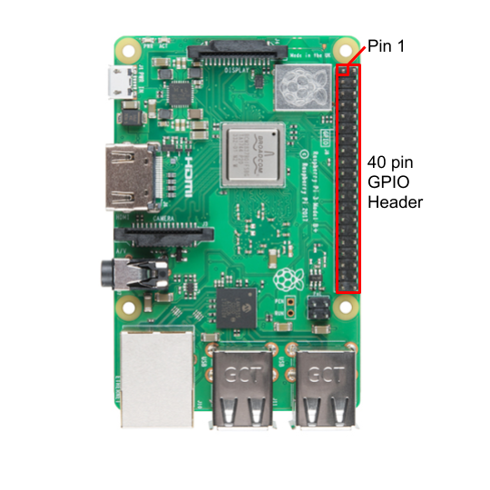
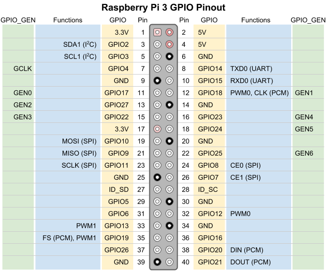
Note that pin 1 is on the top left of the header, as shown in the photo. With pin 1 in this position, we can see what each of the pins is used for:
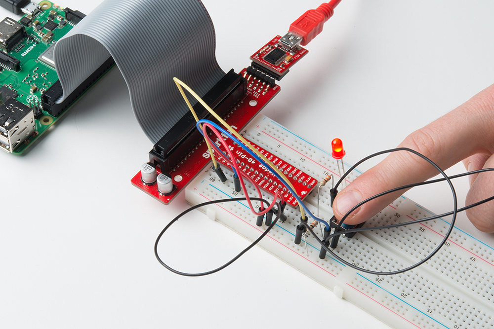
Hardware Connections
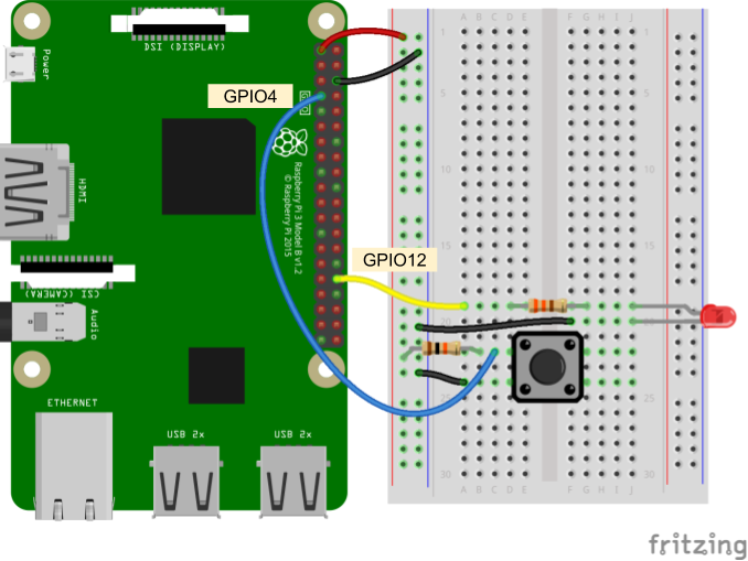
You can connect the Raspberry Pi to the LED and button directly, or you can go through the SparkFun Pi Wedge to make the connections easier on a breadboard. The important thing is to note that we are using the GPIO numbers in our code (listed as Gx on the Pi Wedge, where x is the GPIO number). These GPIO numbers are shown in the yellow boxes in the GPIO Pinout diagram above.
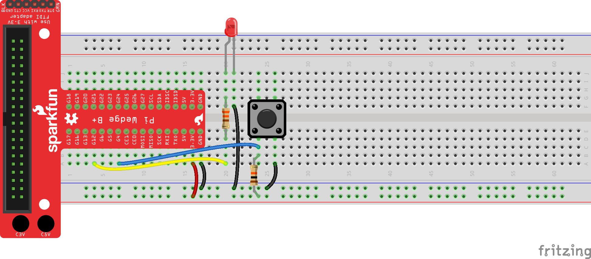
- Connect GPIO12 (pin 32) to the 330Ω resistor, and the resistor to the LED
- Connect GPIO4 (pin 7) to the button
- Make the power (3.3 V) and ground (GND) connections as shown in the Fritzing diagram
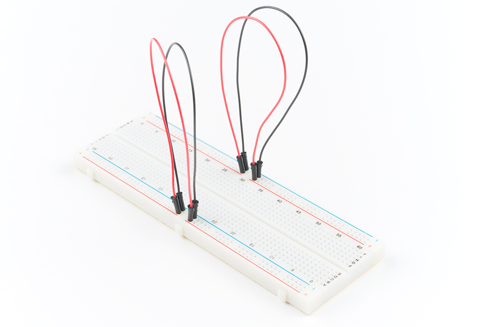
If you have a Pi Wedge, it can make connecting to external hardware on a breadboard easier. If you don't, you can still connect directly to the Raspberry Pi with jumper wires.
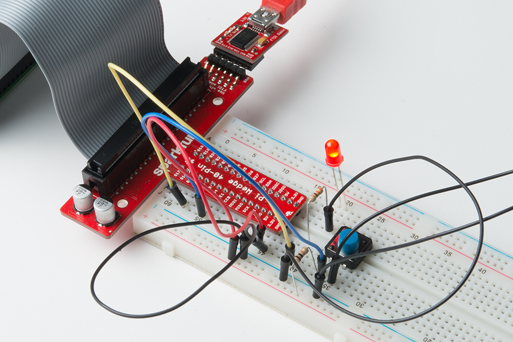
Connecting through a Pi Wedge:
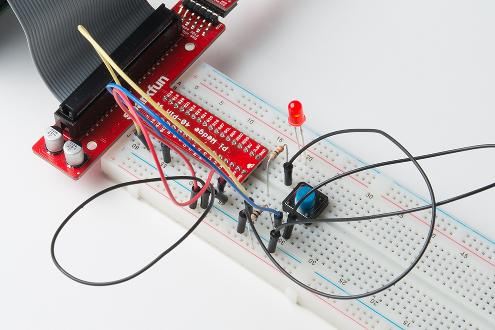
Connecting directly to the Raspberry Pi:


Code Part 1: Blinking an LED
Depending on your version of Raspbian, you may or may not have to install the RPi.GPIO package (e.g. Raspbian Lite does not come with some Python packages pre-installed). In a terminal, enter the following:
language:bash
pip install rpi.gpio
In a new file, enter the following code:
language:python
import time
import RPi.GPIO as GPIO

# Pin definitions
led_pin = 12

# Suppress warnings
GPIO.setwarnings(False)

# Use "GPIO" pin numbering
GPIO.setmode(GPIO.BCM)

# Set LED pin as output
GPIO.setup(led_pin, GPIO.OUT)

# Blink forever
while True:
    GPIO.output(led_pin, GPIO.HIGH) # Turn LED on
    time.sleep(1)                   # Delay for 1 second
    GPIO.output(led_pin, GPIO.LOW)  # Turn LED off
    time.sleep(1)                   # Delay for 1 second
Save the file (I named my file blink.py). Run the code from the terminal by entering:
language:bash
python blink.py
You should see your LED begin to blink on and off every second:
Once you've gotten bored of watching the LED, end the program by pressing ctrl + c.
pip install RPi.GPIO in a terminal.Code to Note:
To control hardware from the Raspberry Pi, we rely on the RPi.GPIO module. This module (likely known as a "library" in other languages) is specifically designed to help us toggle pins and talk to other pieces of hardware. Lucky for us, it comes pre-packaged with Raspbian!
In the first two lines, you see that we imported modules, but we added a few things onto those imports. First up, we used the keyword as:
language:python
import RPi.GPIO as GPIO
RPi.GPIO is the name of the module. By saying as GPIO, we change how we want to refer to that module in the rest of the program. This allows us to type
language:python
GPIO.output(led_pin, GPIO.HIGH)
instead of the much longer
language:python
RPi.GPIO.output(led_pin, RPi.GPIO.HIGH)
While it's generally not a good idea to disable warnings while coding, we added the following line:
language:python
GPIO.setwarnings(False)
Without it, you'll get a warning from the interpreter when you try to run the blink program again:
language:python
blink.py:14: RuntimeWarning: This channel is already in use, continuing anyway.  Use GPIO.setwarnings(False) to disable warnings.
  GPIO.setup(led_pin, GPIO.OUT)
This is because we did not shut down the GPIO 12 pin nicely when we exited the program. To do this, we would want to add a GPIO.cleanup() line at the end of our program. However, because we wrote our program to run forever, we have to interrupt the program to stop it (and a call to cleanup() would never occur). For the time being, it's enough to just ignore the warnings.
Challenge: Change the program to make the LED blink like a heartbeat: 2 quick flashes in succession and then a longer delay.
Code Part 2: Fading an LED with PWM
We've seen how to turn an LED on and off, but how do we control its brightness levels? An LED's brightness is determined by controlling the amount of current flowing through it, but that requires a lot more hardware components. A simple trick we can do is to flash the LED faster than the eye can see!
By controlling the amount of time the LED is on versus off, we can change its perceived brightness. This is known as pulse width modulation (PWM). We have two separate PWM channels for our use: PWM0 and PWM1. We can output a PWM signal on PWM0, which will show up on GPIO12 and GPIO18. Additionally, PWM1 controls the signal for GPIO13 and GPIO19.
Copy the following code into a file (e.g. pwm.py):
language:python
import time
import RPi.GPIO as GPIO

# Pin definitions
led_pin = 12

# Use "GPIO" pin numbering
GPIO.setmode(GPIO.BCM)

# Set LED pin as output
GPIO.setup(led_pin, GPIO.OUT)

# Initialize pwm object with 50 Hz and 0% duty cycle
pwm = GPIO.PWM(led_pin, 50)
pwm.start(0)

# Set PWM duty cycle to 50%, wait, then to 90%
pwm.ChangeDutyCycle(50)
time.sleep(2)
pwm.ChangeDutyCycle(90)
time.sleep(2)

# Stop, cleanup, and exit
pwm.stop()
GPIO.cleanup()
Run it (e.g. python pwm.py), and you should see the LED start dim, wait 2 seconds, grow brighter, wait another 2 seconds, and then turn off before exiting the program.
Code to Note:
In the first part, we use the .output() function of the GPIO module to toggle the LED. Here, we create PWM object and store it in the variable pwm. We do this with the line:
language:python
pwm = GPIO.PWM(led_pin, 50)
From there, we can control the PWM by calling methods within that object. For example, we change the brightness by calling:
language:python
pwm.ChangeDutyCycle(t)
where t is some number between 0-100 (0 being off and 100 being always on). Putting in the number 50 would mean that the LED is on half the time and off the other half the time (it's just toggling so fast that you can't see it!).
Also, we left out the GPIO.setwarnings() call, since we can actually call GPIO.cleanup() at the end of our program! If you try to run the PWM code twice, you should not see any warnings.
Challenge: Make the LED slowly fade from off to fully bright over the course of about 2 seconds. Once it has reached maximum brightness, the LED should turn off and repeat the fading process again. Have the LED fade on over and over again forever.
Code Part 3: Button Input
Let's add some user input! Save the following to a file (such as button.py).
language:python
import time
import RPi.GPIO as GPIO

# Pins definitions
btn_pin = 4
led_pin = 12

# Set up pins
GPIO.setmode(GPIO.BCM)
GPIO.setup(btn_pin, GPIO.IN)
GPIO.setup(led_pin, GPIO.OUT)

# If button is pushed, light up LED
try:
    while True:
        if GPIO.input(btn_pin):
            GPIO.output(led_pin, GPIO.LOW)
        else:
            GPIO.output(led_pin, GPIO.HIGH)

# When you press ctrl+c, this will be called
finally:
    GPIO.cleanup()
Run it the code (python button.py). Now, when you press the button, the LED should turn on.
Code to Note:
The first odd thing you might notice is the try: and finally: statements. These are part of the error and exception handling abilities in Python (you can read more about them in the Exceptions chapter in Byte of Python).
If we press ctrl + x while the program is inside the while True: loop, an exception will be thrown. We don't care to do anything with that exception (hence why you don't see an except block, like you might have read about in "exception handling"). Regardless of whatever the exception is, we do want to call our GPIO.cleaup() function. That way, we can close down the GPIO and not have to worry about any more errors!
The other odd thing you might see is that if GPIO.input(btn_pin) is True (which means the pin is logic high, or 3.3V), we turn the LED off. Wait, what?
In our circuit, our button has a pull-up resistor connecting one of the pins to a constant 3.3V. This means that in its default state (not pressed), the pin connected to the button is 3.3V. When we press the button, the pin is connected to ground (through the button's internal contacts), and the pin becomes logic low (0V).
As a result, when the button is not pressed, we get logic high (GPIO.input() returns True), and when the button is pressed, we get logic low (GPIO.input() returns False).
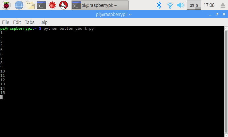
Challenge: Write a program so that whenever you press the button, a variable is incremented by one and is printed to the screen. This should work as a simple button counter. Start at 0, and each time you press the button, it counts up on the screen.