LilyPad Development Board Activity Guide
 Gella
Gella 
2: Basic Color Mixing
Now that you know how to turn LEDs on and off, let's try controlling a colorful LED. The LilyPad Development Board has a tri-color, or RGB (Red Green Blue), LED that can be controlled in your code just like the LED from the last activity. Unlike the LED used in the Blink example, this LED is special - it is actually 3 small LEDs in one package - a red, green, and blue. You can access them in code to a variety of color combinations.
LilyPad Boards Used in This Activity
- LilyPad Arduino Simple
- LilyPad Tri-Color LED
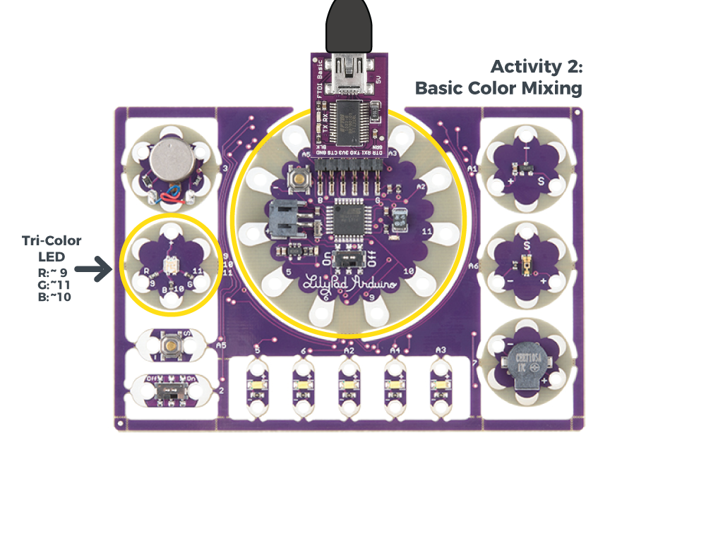
Inside an RGB LED are three smaller LEDs - a red, green, and blue. Each of these LEDs is connected to a sew tab on the Tri-Color LED, and they are all connected through a common anode (positive) pin. Unlike other RGB LEDs, this configuration means that to light up the LED you need to ground the individual red, green, and blue LEDs instead of sending them power.

New Concepts Introduced in This Activity
Declaring and Using Variables
A variable is a placeholder for values in your code, typically a descriptive word. While we could continue to write the sew tab or pin number we are referencing in our programs, a variable can make it easier to read, update, and share information within your code. Every time you want to create and use a variable, you must declare it - tell the program what type of data it is storing.
Creating and Naming Variables
Variables can be whatever word or phrase you like, except for specific reserved words within the Arduino IDE that are used for commands, functions, or other specified use. You can learn more about variable types and use on the Arduino Reference site.Examples:
myvariable,MYVARIABLE,myVariable: variables can use a combination of upper case and lower case. It is common to use camel case to make a variable easier to read.my_variable: an underscore is also an option, but no other symbols.myVariable1: you can use numbers within a variable name, but cannot begin with a number
Tips for Naming Your Variables:
- Use a short, easy to read or type name (up to 63 characters are accepted)
- Use a meaningful word or phrase for your variables, such as the name of a sensor you are connecting your LilyPad Arduino Simple (or name and number if using more than one of the same type) or type of value it will be used for storing (such as brightness, duration, or ).
Color Mixing
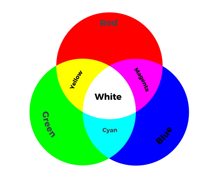
In order to create colors with the RGB LED, you'll have to set each of the LEDs within it individually. The combination of light from the LEDs mixed together creates new colors.
Example Code
To open the code, go to:
File > Examples > LilyPadDevelopmentBoard_ActivityGuide > LPD_02_BasicColorMixing
You can also copy and paste the following code into the Arduino IDE. Hit upload, and see what happens!
language:c
/*
LilyPad Development Board Activity 2: Basic Color Mixing
SparkFun Electronics
https://www.sparkfun.com/products/11262

Create primary and secondary colors on the tri-color (Red/Green/Blue)
LED connected to sew tabs 9, 11, and 10 on the LilyPad Arduino Simple.

Follow the tutorial at:
https://learn.sparkfun.com/tutorials/lilypad-development-board-activity-guide/2-basic-color-mixing

This code is released under the MIT License (http://opensource.org/licenses/MIT)

******************************************************************************/

// The LilyPad Development Board has a tri-color, also known as an RGB
// (Red / Green / Blue) LED.
// In this activity we'll use digitalWrite to tun the three LEDs on and off
// in various combinations to create eight primary and secondary colors.

// Create integer variables for our LED pins:

// The built-in LED:

int RGB_red = 9;
int RGB_green = 11;
int RGB_blue = 10;


void setup()
{
  // Make all of our LED pins outputs:

  pinMode(RGB_red, OUTPUT);
  pinMode(RGB_green, OUTPUT);
  pinMode(RGB_blue, OUTPUT);

}

void loop()
{

  // This code will step through the six primary and secondary colors, plus white and black.
  // Note: for this particular LED, the wiring shares a common anode (+), which means to
  // turn on the LEDs you will set them LOW instead of HIGH.
  // Keep this in mind as you prototype with the LED and mix your colors.

  // For each of these colors, we'll turn the necessary RGB LEDs on or off.


  // Black (all LEDs off)

  // RGB LEDs:

  digitalWrite(RGB_red, HIGH);
  digitalWrite(RGB_green, HIGH);
  digitalWrite(RGB_blue, HIGH);
  delay(1000);

  // Red (red LED on)

  digitalWrite(RGB_red, LOW);
  digitalWrite(RGB_green, HIGH);
  digitalWrite(RGB_blue, HIGH);
  delay(1000);

  // Yellow (red and green LEDs on)

  digitalWrite(RGB_red, LOW);
  digitalWrite(RGB_green, LOW);
  digitalWrite(RGB_blue, HIGH);
  delay(1000);

  // Green (green LED on)

  digitalWrite(RGB_red, HIGH);
  digitalWrite(RGB_green, LOW);
  digitalWrite(RGB_blue, HIGH);
  delay(1000);

  // Cyan (blue and green LEDs on)

  digitalWrite(RGB_red, HIGH);
  digitalWrite(RGB_green, LOW);
  digitalWrite(RGB_blue, LOW);
  delay(1000);

  // Blue (blue LED on)

  digitalWrite(RGB_red, HIGH);
  digitalWrite(RGB_green, HIGH);
  digitalWrite(RGB_blue, LOW);
  delay(1000);

  // Magenta (red and blue LEDs on)

  digitalWrite(RGB_red, LOW);
  digitalWrite(RGB_green, HIGH);
  digitalWrite(RGB_blue, LOW);
  delay(1000);

  // White (all LEDs on)

  digitalWrite(RGB_red, LOW);
  digitalWrite(RGB_green, LOW);
  digitalWrite(RGB_blue, LOW);
  delay(1000);
}
What You Should See
After uploading your code, the RGB LED will step through a color sequence beginning with all LEDs off ('black'), red, yellow, green, cyan, blue, magenta, and white. Once the color sequence is complete, the program will loop back to the beginning and repeat the sequence.
As mentioned before, this RGB LED is a common anode, meaning power is shared by each of the LEDs within it. In order to complete the circuit and turn on the LEDs, the negative (ground) tab of each LED must be connected. We do this in code by using LOW. This is the reverse of the other LEDs used on the board, keep that in mind as you prototype. Not all RGB LEDs are wired this way, so make sure to check the specifications of an LED to confirm the wiring before you use.
Turning on different combinations of three LEDs inside the RGB LED will create new colors. Combining the primary colors of light (red, green, and blue) gives different results than combining pigments in paints or inks. Turning on all three colors will create white - this is called additive color. Take a look a the graphic below to see what colors combine to create primary and secondary colors with light.
Understanding Your Program
Program Overview
- Turn all of the LEDs off by turning on all the pins associated with their variables.
Wait 1 second. - Display red:
R: ON, G: OFF, B: OFF
Wait 1 second. - Display yellow:
R: ON, G: ON, B: OFF
Wait 1 second. - Display green:
R: OFF, G: ON, B: OFF
Wait 1 second. - Display cyan:
R: OFF, G: ON, B: ON
Wait 1 second, - Display blue:
R: OFF, G: OFF, B: ON
Wait 1 second. - Display magenta:
R: ON, G: OFF, B: ON
Wait 1 second. - Display white:
R: ON, G: ON, B: ON
Wait 1 second. - Repeat.
Code to Note
| Code | Description |
|---|---|
int RGB_red = 9;int RGB_green = 11;int RGB_blue = 10; |
Integer Variables:In this program, we set variables for each of the colored LEDs we are using. Each variable has a descriptive name, which will help us easily keep track of color as we set the individual LEDs in the RGB LED to create color combinations. Notice theint before all the variables used in this program - "int" is short for integer. In addition to deciding the type of data stored in the variable, we can also intialize or preset the information in the variable. In this program, the variables store the number of the sew tab each LED is connected to. We will cover more ways to use variables in later activities, including different variable types. Variables are case sensitive, so make sure you type them identically each time you use in your program. |
pinMode(RGB_red, OUTPUT);pinMode(RGB_green, OUTPUT);pinMode(RGB_blue, OUTPUT); |
Input or Output?:Each LED you want to control needs to be declared individually as anOUTPUT, even the built-in LEDs within the RGB LED. These use the same format from the Blinking LEDs example, but replacing the sew tab number with the variable names declared at the start of the program. |
digitalWrite(RGB_red, LOW);digitalWrite(RGB_green, HIGH);digitalWrite(RGB_blue, HIGH); |
Creating Colors:Take a look at the code and notice the RGB LED variables are grouped together. In this code, instead of usingdigitalWrite() and delay() to create a blink, we are using these commands to step through new colors by turning different combinations of the red, green, and blue channels HIGH and LOW. Examine the code to see how setting these LEDs on or off matches the color chart above.Note that for the tri-color LED, LOW turns the LEDs on and HIGH turns them off. |
Coding Challenges
Can you create a new color sequence on the tri-color LED using a new order of colors being displayed?
Try changing the delay to create a faster or slower color sequence.
Create a variable called
delayTimeat the top of your code near the other variable declarations. Then replace the 1000 in eachdelay()function with this variable. This way you can easily set the delay between color steps once at the beginning of your code instead of copying and pasting in each part of the sequence.