LilyPad Development Board Activity Guide
 Gella
Gella 
Introduction
Note to Users:
This resource is an adapted version of the LilyPad ProtoSnap Plus Activity Guide for users who want to follow along with the LilyPad Development Board.The LilyPad ProtoSnap Plus is the latest version of this board.
This guide will get you started with some introductory programming activities exploring each of the LilyPad pieces on the LilyPad Development Board. If you've never used Arduino to program before, this guide will walk you through the basics with example code to upload and explore.
You can follow along with this guide with both the LilyPad Development Board, available individually or in a Lab Pack. This guide will not cover construction of a project with conductive thread, so either product will work for you.
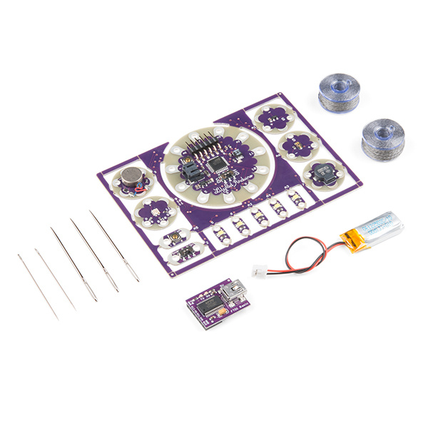
LilyPad ProtoSnap Development Board
DEV-11262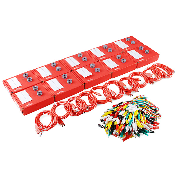
LilyPad Lab Pack
LAB-11762Required Materials
If using the LilyPad Development Board individual kit, you will need to supply your own Mini-B USB cable to upload code. The LilyPad Lab Pack includes cables.

USB Mini-B Cable - 6 Foot
CAB-00598Suggested Reading
What is an Arduino?
LilyPad Development Board Hookup Guide
Getting Started with LilyPad
Before You Begin
Note: This guide assumes you are using the latest version of the Arduino IDE on your desktop. If this is your first time using Arduino, please review our tutorial on installing the Arduino IDE. If you have not previously installed an Arduino library, please check out our installation guide.
Installing Arduino IDE
Download LilyPad Development Board Example Code
To follow along with the activities in this guide, download the LilyPad Development Board Example Code. Click the following link to download the code:
Place the LilyPadDevelopmentBoard_ActivityGuide folder in the Arduino IDE examples directory:
- Windows: drag the
LilyPadDevelopmentBoard_ActivityGuidefolder intoC:\program files\Arduino-x\examples - MacOS: Right-click on the Arduino IDE app and click "Show Package Contents...". Drag the
LilyPadDevelopmentBoard_ActivityGuidefolder intoContents/Resources/Java - Linux: see http://www.arduino.cc/playground/Learning/Linux
You can also download the code from GitHub.
Install FTDI Drivers
If you've never used a LilyPad Arduino before, you will need to install FTDI drivers. Depending on your computer’s operating system, you will need to follow specific instructions. Please go to How to Install FTDI Drivers, for specific instructions on how to install the FTDI drivers onto your computer.
USB Serial Driver Quick Install
Note that you won't have to install the FTDI drivers again, but you will need to perform the below three steps every time you want to program the board. These three steps are:
2. Select "LilyPad Arduino" from Arduino's "Board" menu.
3. Select "ATmega328" from Arduino's "Processor" menu.
4. Select the serial port the LilyPad is connected to from Arduino's "Port" menu.
Let's go over the three steps in detail:
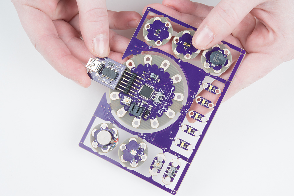
1. Connect the LilyPad Development Board to Your Computer
Place the LilyPad Development Board on a clean, non-metal work surface. Connect the LilyPad FTDI Board to the headers on the LilyPad Arduino Simple at the center of the Development Board.
Connect the other side of the FTDI board to a mini-B USB cable.The cable can only be inserted one way, and should snap in securely.
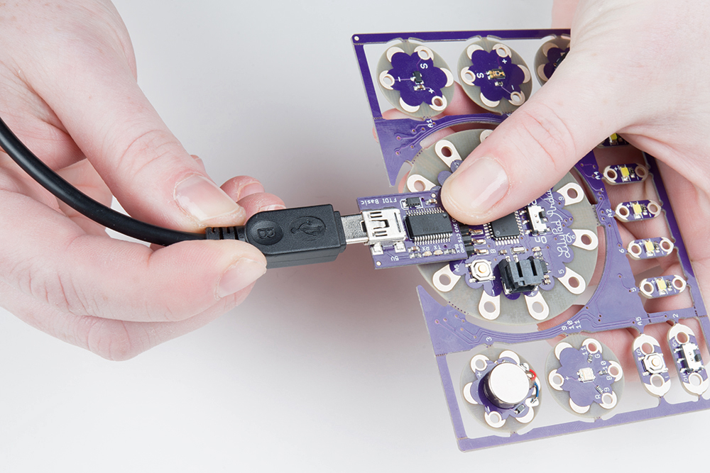
Then connect the other end of the USB cable to a USB port on your computer.
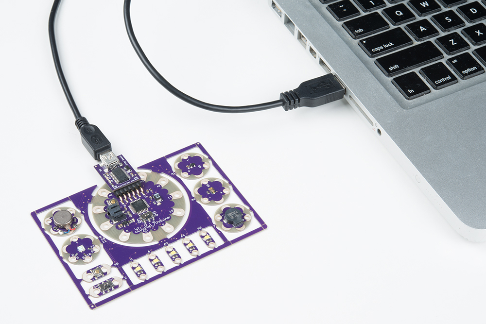
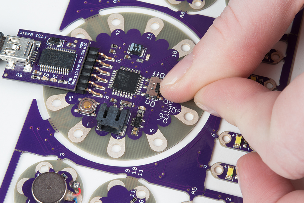
Slide the switch on the LilyPad Arduino to the ON position. You will not be able to upload code to the board if it is set to the OFF position.
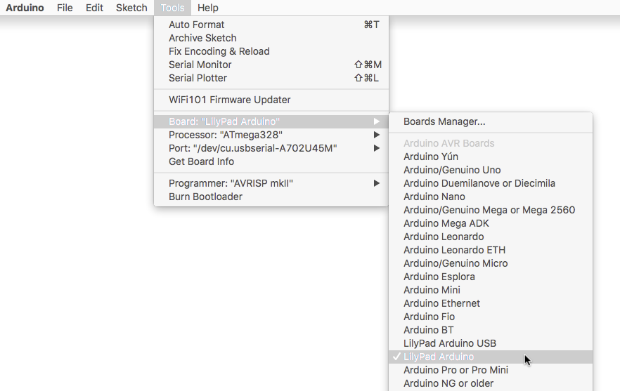
2. Select LilyPad Arduino from the Board Menu
To program the LilyPad Arduino Simple at the center of the LilyPad Development Board, open the Tools > Board list and select LilyPad Arduino. A dot (Windows) or check mark (Mac) will show next to the board in the menu when it is selected, and it will show next to Board in the Tools menu.
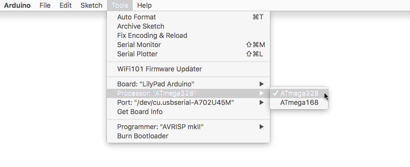
3. Select ATmega328 from the Processor Menu
After selecting the LilyPad Arduino, there will be two options available in the next menu down labeled Processor. Select ATmega328 for your LilyPad Arduino.
4. Select Port from the Port Menu
Arduino needs to know which port your LilyPad Arduino is attached to so it can program it. Whenever you plug a USB device into your computer, your computer will assign it a port number. Go to the Tools > Port menu, and select the port that has the LilyPad Arduino attached to it.
On Windows ports are listed as COM##; on a Mac or Linux machine they will be "/dev/cu.usbmodem####". Your screen may look different than the image below, depending on what operating system you are using.

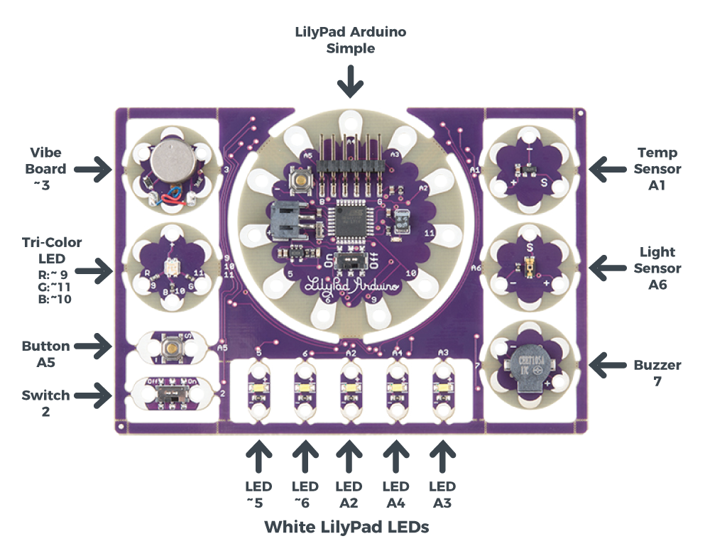
Hardware Overview
The LilyPad Development Board features twelve LilyPad components connected to a LilyPad Arduino Simple microcontroller by conductive pathways called traces. Many of these traces are hidden, but for reference, each component on the ProtoSnap has a nearby label with the number of the LilyPad Arduino Simple sew tab it is connected to. For more information on features and technical specs, please refer to the LilyPad Development Board Quickstart Guide.
What is a Program?
Programs are sets of instructions that tell a computer to do something, (also called “code” or a “sketch” in Arduino) . This could be blinking LEDs, playing sounds, making decisions based on input from sensors, or a combination of all those things.
When the computer runs a program, it will start at the first instruction, carry it out, and move on to the next one. These instructions come from a specific list of words that the computer knows. If you type in a word that the computer doesn’t know (or more likely, you misspell a word that the computer should know), you’ll get an error when you try to run your program. Don’t feel bad, this happens to everyone and is a normal part of writing programs, and we’ll provide you with some troubleshooting tips as you follow along with the activities in this guide.
In the Arduino system, you’ll write programs on your computer in a free application called the Arduino IDE (“IDE” stands for Integrated Development Environment). This is a specialized text editor with extra buttons to check and send your code to the LilyPad Arduino Simple at the center of your ProtoSnap board. We've created a set of of programming examples that you copied to a folder in the Arduino application, we’ll be using them in these activities.
What is a Microcontroller?
The LilyPad Arduino Simple at the center of your ProtoSnap board contains a tiny computer called a microcontroller. It can’t do all the things that a larger computer does, but it’s very good at running programs that control simple hardware like LEDs.
Unlike larger computers, microcontrollers don’t have keyboards and screens for input and output. Most of your input and output will happen through sew tabs; the silver petals with holes in them evenly spaced around the outer edge of all LilyPad boards. Your program can control the sew tabs. It can use them for output by turning them on and off (internally connecting them to voltage or not). It can also use them for input, measuring any voltage coming from other components. It can use this information to read buttons, switches, and various sensors, and use that information to make decisions. (We’ll explore this in future activities.)
If you look closely at the sew tabs, you’ll see that every sew tab has a label next to it. These are the names of the sew tabs, which you’ll need to know to control them from your program. You might have noticed that some of the sew tabs have an “A” as part of the label, and some include a tilde or squiggle “~”. These symbols describe special features that some of the sew tabs have. We’ll tell you about these special features in future activities.
Some of the sew tabs have a “+” or “-” next to them. You can use these sew tabs to provide power and ground to LilyPad boards connected to the LilyPad Arduino Simple.
Sew Tabs and Pins
Every microcontroller chip has electrical connections to the board that look like metal legs. These are commonly referred to as pins. Each sew tab around the outside edge of the LilyPad Arduino Simple is connected electrically to one of these pins on the microcontroller chip. In this guide, we'll be referring to sew tabs when referencing the hardware and electrical connections on your ProtoSnap and pins when talking about the code that controls electricity in or out of the tabs.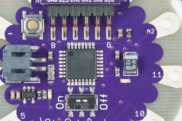
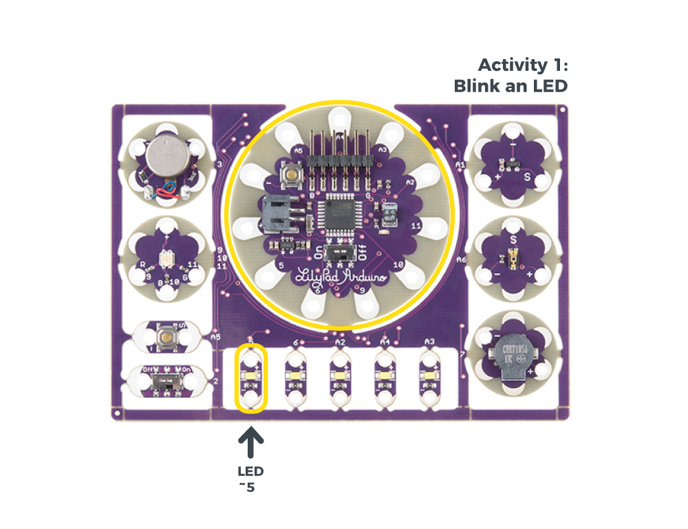
1: Blink an LED
In this activity, you’ll run your first program on the LilyPad Arduino Simple at the center of the LilyPad Development Board. It will “just” make an LED blink, but there’s a lot going on even in this simple task. Let's get started!
LilyPad Boards Used in This Activity
- LilyPad Arduino Simple
- LilyPad LED
“LED” stands for “Light Emitting Diode”. These are electronic components that light up when electricity passes through them. They are available in a variety of colors; your LilyPad Development Board includes five white LEDs and a special tri-color "red-green-blue" (RGB) LED that can display a rainbow of colors.
New Concepts Introduced in This Activity
Exploring Your First Program
We've provided a pre-written example program that we'll load into the Arduino IDE.
Basic Program Structure
We'll walk you through the example program, explain how it's constructed, and go over the two basic functions every program needs; setup() and loop().
Lighting Up LEDs
We'll show you how to light up and blink an LED using the pinMode(), digitalWrite(), and delay() commands.
Modifying Code
A great way to learn to program is to make small changes to a program that someone else has written, and see what happens. We'll suggest places to try this, and give you a few challenges at the end of each activity.
Example Code
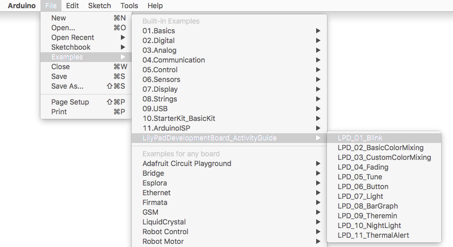
For each of these activities, we'll start with a pre-written program that you'll explore and modify. To load the first program, start up the Arduino IDE and go to:
File > Examples > LilyPadDevelopmentBoard_ActivityGuide > LPD_01_Blink
You can also copy and paste the following code into the Arduino IDE (be sure to delete any code already in the window first).
language:c
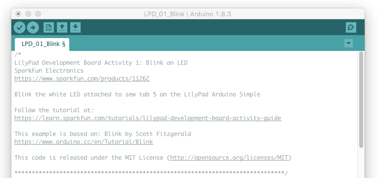
/*
LilyPad Development Board Activity 1: Blink an LED
SparkFun Electronics
https://www.sparkfun.com/products/11262
Blink the white LED attached to sew tab 5 on the LilyPad Arduino Simple
Follow the tutorial at:
https://learn.sparkfun.com/tutorials/lilypad-development-board-activity-guide/1-blink-an-led
This example is based on: Blink by Scott Fitzgerald
https://www.arduino.cc/en/Tutorial/Blink
This code is released under the MIT License (http://opensource.org/licenses/MIT)
******************************************************************************/
// The setup function runs once when the microcontroller starts up or resets:
void setup()
{
// Before you use a sew tab (pin), you must set it to be either an input or output:
pinMode(5, OUTPUT); // Set pin 5 to be an output
}
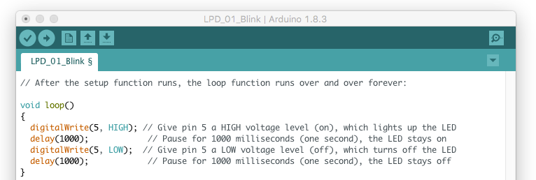
// After the setup function runs, the loop function runs over and over forever:
void loop()
{
digitalWrite(5, HIGH); // Give pin 5 a HIGH voltage level (on), which lights up the LED
delay(1000); // Pause for 1000 milliseconds (one second), the LED stays on
digitalWrite(5, LOW); // Give pin 5 a LOW voltage level (off), which turns off the LED
delay(1000); // Pause for 1000 milliseconds (one second), the LED stays off
}
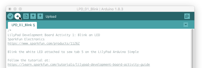
Once you've connected your LilyPad Development Board to your computer as shown in the Before You Begin section, and loaded or copied the example program into the Arduino IDE, click the upload button (the round button with the right arrow at the top of the window) and see what happens!
What You Should See
Once the code has uploaded, the first white LED in the bottom row on the Development Board will blink once per second.
Understanding Your Program
In this section, we'll explain what this program does. For this first activity we'll be pretty thorough. As we progress through future activities, we’ll just highlight new concepts as we introduce them.
Program Overview
- Turn the LED on by sending power to Pin 5.
- Wait 1 second.
- Turn the LED off by cutting power to Pin 5.
- Wait 1 second.
- Repeat.
Comments
At the top of the program, you'll find text describing what the program does, who wrote it, etc. These are called comments. They are there solely for your information and are ignored by the microcontroller. Comments in the Arduino IDE will show up as gray text.
We use special symbols to tell the microcontroller to ignore comments.
If you want to write a block of text on multiple lines as we've done above, the microcontroller will ignore any text between
/*and*/.If you want to put a comment on a single line, the microcontroller will ignore any text after two slashes
//.
Setup() Function
The next section of our program contains a function. A function is a named block of code that does a defined task or set of tasks. When a function is run, all of the code contained between the curly brackets { and } is run. Arduino has two essential functions that are required for every program to run properly: they are setup() and loop(). Arduino programs can use many functions (both built-in and user defined), but they must at least have those two. These and other control structure functions built into the Arduino software will display in green text. Let's explore the setup function.

When the microcontroller starts up or is reset, the setup() function runs once. As you may have guessed from the name, the setup() function is typically used to "set up" the hardware so that it operates properly during the rest of the program.
Statements and Commands
Inside functions, we put statements. A statement is a single instruction to the microcontroller. Statements always end with semicolons ;. It's a common error to forget the semicolon, so if you get an error when uploading your code, double-check that every statement ends with ;.
Most statements will include commands. Commands are specific functions you can use to complete common tasks in Arduino. There are many built-in commands that can be used for all sorts of things - input and output, math, decision making, etc. These commands display in orange text. We'll cover many useful commands in this guide.
In this program, we’ve put one command in the startup function, called pinMode(). Note the unusual capitalization, called "camel case". Commands are case-sensitive, so pay special attention to this.
The pinMode() command, as you may have guessed, sets the mode of a pin. Pins are the metal legs on microcontroller chips that are attached to the sew tabs on your LilyPad board. Pins can be configured as inputs or outputs. In this program, we’re going to use pin 5 to control an LED, which is a component sending information (light) to the world, so we'll make it an OUTPUT.
Commands take various numbers of parameters, which are the information the command needs from you. Parameters go inside parentheses () after a command, and are separated by commas if there are multiple. The pinMode command takes two parameters; the number of the pin, and whether you want it to be an INPUT or an OUTPUT. Here, we're setting pin 5 to be an OUTPUT.
Reserved Words in Arduino IDE
You may have noticed some parameters are shown in blue text and others plain black. Colored text indicates one of Arduino's reserved words. A reserved word can be a variable, function, or command that has a specified use in the Arduino software. If you are typing something in your code and it displays in colored text, it has a pre-set meaning for Arduino. We'll learn more about variable naming in the next activity. For a full list of reserved words, visit the Arduino Reference website.Loop() Function
The second essential function needed to run an Arduino program is called loop(). After the setup() function runs once, the loop() function runs over and over, forever (or until you turn off or reset the microcontroller).
A loop() function usually contains the main tasks and behaviors of your program; the things you want it to do repeatedly. You can use this to your advantage; for example, in this program we want to blink an LED continuously. Because the loop() function repeats, we only need to write the code to blink it once, and the loop() function will make it blink over and over.
The first thing we'll do is turn our LED on. To do that, we'll use the digitalWrite() command.
Like pinMode(), digitalWrite() takes two parameters: the pin we want to control, and whether we want to make the pin a HIGH voltage level (on), or a LOW voltage level (off). We want to turn the LED on, so we'll set pin 5 to HIGH.
Because the microcontroller runs so fast, if we immediately turned the LED off, you'd never notice it. So we'll slow things down with a command called delay() that does nothing but pause the program for a set amount of time.
The delay() function takes one parameter, the number of milliseconds to wait. There are 1000 milliseconds in one second, so here we're pausing for one second. If you make this value smaller, the LED will blink faster, and vice-versa. Try it!
After we've waited one second, we'll turn the LED off with a second digitalWrite(), this time setting the pin to LOW to turn the LED off.
Finally, we'll add a second delay(). This one pauses while the LED is off, finishing the complete on-off "blink" cycle. If we didn't have the second delay(), the LED would immediately turn on again when loop() starts over. This happens so quickly you wouldn't notice it being off.
Coding Challenges
Try changing the number inside
delay()- Can you make the LED blink faster or slower?Changing the pin number inside the
digitalWrite()function will change the sew tab being controlled by the code. Can you light up one of the other LilyPad LEDs on the ProtoSnap by changing this number? Hint: don't forget to set that LED to be anOUTPUTfirst.Can you modify the code to blink multiple LEDs?
2: Basic Color Mixing
Now that you know how to turn LEDs on and off, let's try controlling a colorful LED. The LilyPad Development Board has a tri-color, or RGB (Red Green Blue), LED that can be controlled in your code just like the LED from the last activity. Unlike the LED used in the Blink example, this LED is special - it is actually 3 small LEDs in one package - a red, green, and blue. You can access them in code to a variety of color combinations.
LilyPad Boards Used in This Activity
- LilyPad Arduino Simple
- LilyPad Tri-Color LED
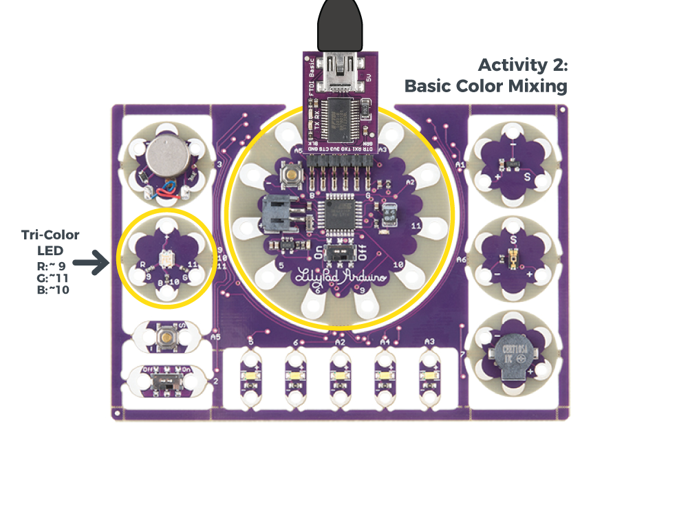
Inside an RGB LED are three smaller LEDs - a red, green, and blue. Each of these LEDs is connected to a sew tab on the Tri-Color LED, and they are all connected through a common anode (positive) pin. Unlike other RGB LEDs, this configuration means that to light up the LED you need to ground the individual red, green, and blue LEDs instead of sending them power.

New Concepts Introduced in This Activity
Declaring and Using Variables
A variable is a placeholder for values in your code, typically a descriptive word. While we could continue to write the sew tab or pin number we are referencing in our programs, a variable can make it easier to read, update, and share information within your code. Every time you want to create and use a variable, you must declare it - tell the program what type of data it is storing.
Creating and Naming Variables
Variables can be whatever word or phrase you like, except for specific reserved words within the Arduino IDE that are used for commands, functions, or other specified use. You can learn more about variable types and use on the Arduino Reference site.Examples:
myvariable,MYVARIABLE,myVariable: variables can use a combination of upper case and lower case. It is common to use camel case to make a variable easier to read.my_variable: an underscore is also an option, but no other symbols.myVariable1: you can use numbers within a variable name, but cannot begin with a number
Tips for Naming Your Variables:
- Use a short, easy to read or type name (up to 63 characters are accepted)
- Use a meaningful word or phrase for your variables, such as the name of a sensor you are connecting your LilyPad Arduino Simple (or name and number if using more than one of the same type) or type of value it will be used for storing (such as brightness, duration, or ).
Color Mixing
In order to create colors with the RGB LED, you'll have to set each of the LEDs within it individually. The combination of light from the LEDs mixed together creates new colors.
Example Code
To open the code, go to:
File > Examples > LilyPadDevelopmentBoard_ActivityGuide > LPD_02_BasicColorMixing
You can also copy and paste the following code into the Arduino IDE. Hit upload, and see what happens!
language:c
/*
LilyPad Development Board Activity 2: Basic Color Mixing
SparkFun Electronics
https://www.sparkfun.com/products/11262

Create primary and secondary colors on the tri-color (Red/Green/Blue)
LED connected to sew tabs 9, 11, and 10 on the LilyPad Arduino Simple.

Follow the tutorial at:
https://learn.sparkfun.com/tutorials/lilypad-development-board-activity-guide/2-basic-color-mixing

This code is released under the MIT License (http://opensource.org/licenses/MIT)

******************************************************************************/

// The LilyPad Development Board has a tri-color, also known as an RGB
// (Red / Green / Blue) LED.
// In this activity we'll use digitalWrite to tun the three LEDs on and off
// in various combinations to create eight primary and secondary colors.

// Create integer variables for our LED pins:

// The built-in LED:

int RGB_red = 9;
int RGB_green = 11;
int RGB_blue = 10;


void setup()
{
  // Make all of our LED pins outputs:

  pinMode(RGB_red, OUTPUT);
  pinMode(RGB_green, OUTPUT);
  pinMode(RGB_blue, OUTPUT);

}

void loop()
{

  // This code will step through the six primary and secondary colors, plus white and black.
  // Note: for this particular LED, the wiring shares a common anode (+), which means to
  // turn on the LEDs you will set them LOW instead of HIGH.
  // Keep this in mind as you prototype with the LED and mix your colors.

  // For each of these colors, we'll turn the necessary RGB LEDs on or off.


  // Black (all LEDs off)

  // RGB LEDs:

  digitalWrite(RGB_red, HIGH);
  digitalWrite(RGB_green, HIGH);
  digitalWrite(RGB_blue, HIGH);
  delay(1000);

  // Red (red LED on)

  digitalWrite(RGB_red, LOW);
  digitalWrite(RGB_green, HIGH);
  digitalWrite(RGB_blue, HIGH);
  delay(1000);

  // Yellow (red and green LEDs on)

  digitalWrite(RGB_red, LOW);
  digitalWrite(RGB_green, LOW);
  digitalWrite(RGB_blue, HIGH);
  delay(1000);

  // Green (green LED on)

  digitalWrite(RGB_red, HIGH);
  digitalWrite(RGB_green, LOW);
  digitalWrite(RGB_blue, HIGH);
  delay(1000);

  // Cyan (blue and green LEDs on)

  digitalWrite(RGB_red, HIGH);
  digitalWrite(RGB_green, LOW);
  digitalWrite(RGB_blue, LOW);
  delay(1000);

  // Blue (blue LED on)

  digitalWrite(RGB_red, HIGH);
  digitalWrite(RGB_green, HIGH);
  digitalWrite(RGB_blue, LOW);
  delay(1000);

  // Magenta (red and blue LEDs on)

  digitalWrite(RGB_red, LOW);
  digitalWrite(RGB_green, HIGH);
  digitalWrite(RGB_blue, LOW);
  delay(1000);

  // White (all LEDs on)

  digitalWrite(RGB_red, LOW);
  digitalWrite(RGB_green, LOW);
  digitalWrite(RGB_blue, LOW);
  delay(1000);
}
What You Should See
After uploading your code, the RGB LED will step through a color sequence beginning with all LEDs off ('black'), red, yellow, green, cyan, blue, magenta, and white. Once the color sequence is complete, the program will loop back to the beginning and repeat the sequence.
As mentioned before, this RGB LED is a common anode, meaning power is shared by each of the LEDs within it. In order to complete the circuit and turn on the LEDs, the negative (ground) tab of each LED must be connected. We do this in code by using LOW. This is the reverse of the other LEDs used on the board, keep that in mind as you prototype. Not all RGB LEDs are wired this way, so make sure to check the specifications of an LED to confirm the wiring before you use.
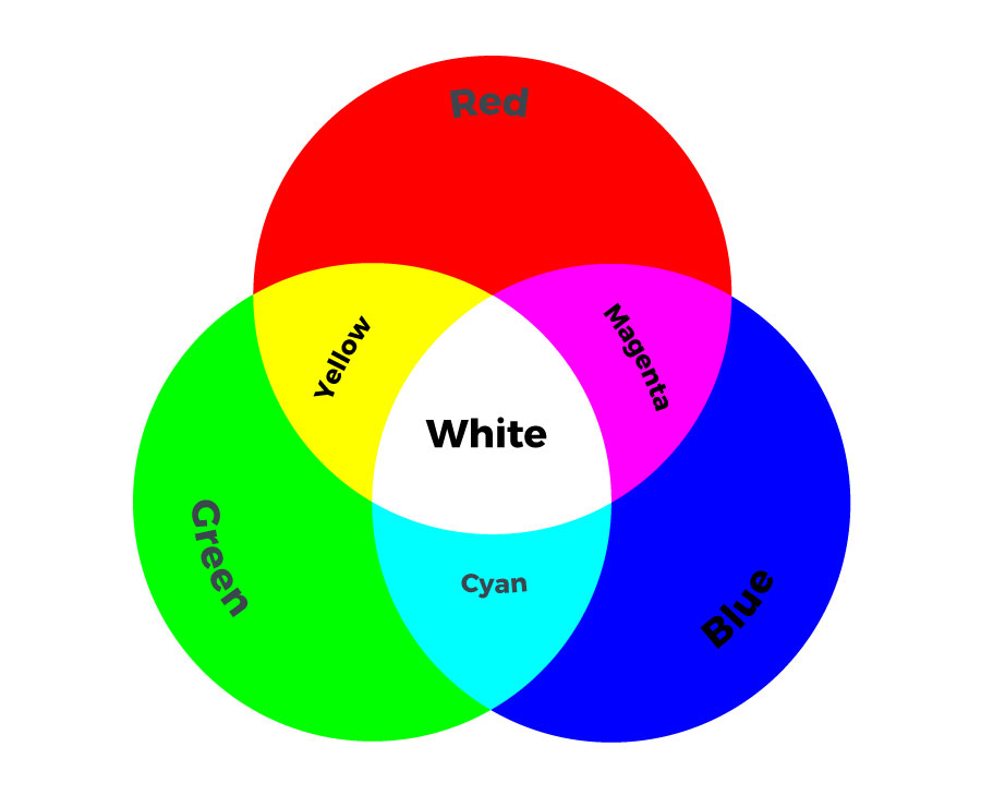
Turning on different combinations of three LEDs inside the RGB LED will create new colors. Combining the primary colors of light (red, green, and blue) gives different results than combining pigments in paints or inks. Turning on all three colors will create white - this is called additive color. Take a look a the graphic below to see what colors combine to create primary and secondary colors with light.
Understanding Your Program
Program Overview
- Turn all of the LEDs off by turning on all the pins associated with their variables.
Wait 1 second. - Display red:
R: ON, G: OFF, B: OFF
Wait 1 second. - Display yellow:
R: ON, G: ON, B: OFF
Wait 1 second. - Display green:
R: OFF, G: ON, B: OFF
Wait 1 second. - Display cyan:
R: OFF, G: ON, B: ON
Wait 1 second, - Display blue:
R: OFF, G: OFF, B: ON
Wait 1 second. - Display magenta:
R: ON, G: OFF, B: ON
Wait 1 second. - Display white:
R: ON, G: ON, B: ON
Wait 1 second. - Repeat.
Code to Note
| Code | Description |
|---|---|
int RGB_red = 9;int RGB_green = 11;int RGB_blue = 10; |
Integer Variables:In this program, we set variables for each of the colored LEDs we are using. Each variable has a descriptive name, which will help us easily keep track of color as we set the individual LEDs in the RGB LED to create color combinations. Notice theint before all the variables used in this program - "int" is short for integer. In addition to deciding the type of data stored in the variable, we can also intialize or preset the information in the variable. In this program, the variables store the number of the sew tab each LED is connected to. We will cover more ways to use variables in later activities, including different variable types. Variables are case sensitive, so make sure you type them identically each time you use in your program. |
pinMode(RGB_red, OUTPUT);pinMode(RGB_green, OUTPUT);pinMode(RGB_blue, OUTPUT); |
Input or Output?:Each LED you want to control needs to be declared individually as anOUTPUT, even the built-in LEDs within the RGB LED. These use the same format from the Blinking LEDs example, but replacing the sew tab number with the variable names declared at the start of the program. |
digitalWrite(RGB_red, LOW);digitalWrite(RGB_green, HIGH);digitalWrite(RGB_blue, HIGH); |
Creating Colors:Take a look at the code and notice the RGB LED variables are grouped together. In this code, instead of usingdigitalWrite() and delay() to create a blink, we are using these commands to step through new colors by turning different combinations of the red, green, and blue channels HIGH and LOW. Examine the code to see how setting these LEDs on or off matches the color chart above.Note that for the tri-color LED, LOW turns the LEDs on and HIGH turns them off. |
Coding Challenges
Can you create a new color sequence on the tri-color LED using a new order of colors being displayed?
Try changing the delay to create a faster or slower color sequence.
Create a variable called
delayTimeat the top of your code near the other variable declarations. Then replace the 1000 in eachdelay()function with this variable. This way you can easily set the delay between color steps once at the beginning of your code instead of copying and pasting in each part of the sequence.
3: Custom Color Mixing
In this program, you will continue mixing colors with the tri-color LED, but use a new function to change the brightness of each channel in relation to each other. Adjusting the brightness of the red, green, and blue LEDs within the LED will allow you to create a new range of values and color combinations.
LilyPad Boards Used in This Activity
- LilyPad Arduino Simple
- LilyPad Tri-Color LED

New Concepts Introduced in This Activity
Analog Output (Pulse Width Modulation)
Up until this point, you have been controlling LEDs by setting them to one of two states: HIGH (ON) or LOW (OFF). This is great for blinking, but what about adjusting the brightness of your LEDs? This is where analog output comes in handy. Your LilyPad Arduino Simple can mimic a range of brightness on the LEDs by using pulse width modulation. The microcontroller on the LilyPad Arduino Simple can switch voltage to the sew tabs on and off so quickly that it appears to your eyes as if more or less voltage is being provided to an LED. For example, by changing the percent of time that a pin is on, from 0 percent (always off) to 100 percent (always on), you can create the appearance of a range of brightnesses. This percentage is called a duty cycle.
Color Mixing Continued
In the last example, you created basic primary and secondary colors by turning the red, green, and blue channels on or off with different combinations. In this activity, you'll create tertiary colors by combining the three color channels at 50% brightness levels. There are actually millions of color combinations available using RGB LEDs once you begin experimenting with adjusting the brightness/saturation of each. This example will cover a set of twelve tertiary colors.
Example Code
To open the code, go to:
File > Examples > LilyPadDevelopmentBoard_ActivityGuide > LPD_03_CustomColorMixing
You can also copy and paste the following code into the Arduino IDE. Hit upload, and see what happens!
language:c
/*
LilyPad Development Board Activity 3: Custom Color Mixing
SparkFun Electronics
https://www.sparkfun.com/products/11262

Expand your color options using analogWrite and the RGB (Red Green Blue) LED

Follow the tutorial at:
https://learn.sparkfun.com/tutorials/lilypad-development-board-activity-guide/3-custom-color-mixing

This code is released under the MIT License (http://opensource.org/licenses/MIT)

******************************************************************************/
// The LilyPad Development Board has a RGB (Red / Green / Blue) LED attached to it.
// In this activity we'll use analogWrite to control the brightness of the three LEDs.
// Here we'll create a rainbow of tertiary colors by adding a 50%-brightness option.

// Create integer variables for our LED pins:

// The built-in LED:

int RGB_red = 9;
int RGB_green = 11;
int RGB_blue = 10;


void setup() {

// Make all of our LED pins outputs:

  pinMode(RGB_red, OUTPUT);
  pinMode(RGB_green, OUTPUT);
  pinMode(RGB_blue, OUTPUT);
}

void loop()
{
  // In this code we'll step through twelve rainbow colors (primary, secondary, tertiary).

  // Unlike digitalWrite, which can be only HIGH (on) or LOW (off),
  // analogWrite lets you smoothly change the brightness from 0 (off) to 255 (fully on).
  // When analogWrite is used with the RGB LED, you can create millions of colors!

  // In the analogWrite functions:
  // 0 is off
  // 128 is halfway on (used for the tertiary colors)
  // 255 is full brightness.
  // But because this particular LED is common anode, we will need to reverse these
  // numbers to display correctly:
  // 255 is off
  // 128 remains halfway on
  // 0 is full brightness.

  // Red

  analogWrite(RGB_red,0);
  analogWrite(RGB_green,255);
  analogWrite(RGB_blue,255);
  delay(1000);

  // Orange

  analogWrite(RGB_red,0);
  analogWrite(RGB_green,128);
  analogWrite(RGB_blue,255);
  delay(1000);

  // Yellow

  analogWrite(RGB_red,0);
  analogWrite(RGB_green,0);
  analogWrite(RGB_blue,255);
  delay(1000);

  // Chartruese

  analogWrite(RGB_red,128);
  analogWrite(RGB_green,0);
  analogWrite(RGB_blue,255);
  delay(1000);

  // Green

  analogWrite(RGB_red,255);
  analogWrite(RGB_green,0);
  analogWrite(RGB_blue,255);
  delay(1000);

  // Spring Green

  analogWrite(RGB_red,255);
  analogWrite(RGB_green,0);
  analogWrite(RGB_blue,128);
  delay(1000);

  // Cyan

  analogWrite(RGB_red,255);
  analogWrite(RGB_green,0);
  analogWrite(RGB_blue,0);
  delay(1000);

  // Azure

  analogWrite(RGB_red,255);
  analogWrite(RGB_green,128);
  analogWrite(RGB_blue,0);
  delay(1000);

  // Blue

  analogWrite(RGB_red,255);
  analogWrite(RGB_green,255);
  analogWrite(RGB_blue,0);
  delay(1000);

  // Violet

  analogWrite(RGB_red,128);
  analogWrite(RGB_green,255);
  analogWrite(RGB_blue,0);
  delay(1000);

  // Magenta

  analogWrite(RGB_red,0);
  analogWrite(RGB_green,255);
  analogWrite(RGB_blue,0);
  delay(1000);

  // Rose

  analogWrite(RGB_red,0);
  analogWrite(RGB_green,255);
  analogWrite(RGB_blue,128);
  delay(1000);
}
What You Should See
After uploading your code the RGB LED will step through a rainbow sequence of red, orange, yellow, chartruese, green, spring green, cyan, azure, blue, violet, magenta, and rose, repeatedly.
By adjusting the brightness of each LED in the RGB LED individually, we open up a much wider range of color options to display than the previous activity. In fact, there are many more combinations than we show in the example code. The image below shows a chart of the tertiary colors the example program creates by stepping down the LEDs to half brightness, creating a rainbow with more color transitions than the Basic Color Mixing example. By using analog output to adjust the brightness of each color channel individually, the RGB LED can display almost any color you can choose from a color picker - if you are familiar with RGB sliders in a graphics program, you'll recognize the 0-255 values used in this code.
In a typical
analogWrite() function 0 is 0% (OFF) and 255 100% (ON), but because the tri-color LED is common anode, in the code we'll use 0 for 100% (ON) and 255 for 0% (OFF). Refer to the chart below for color mixing values specifically for the tri-color LED. 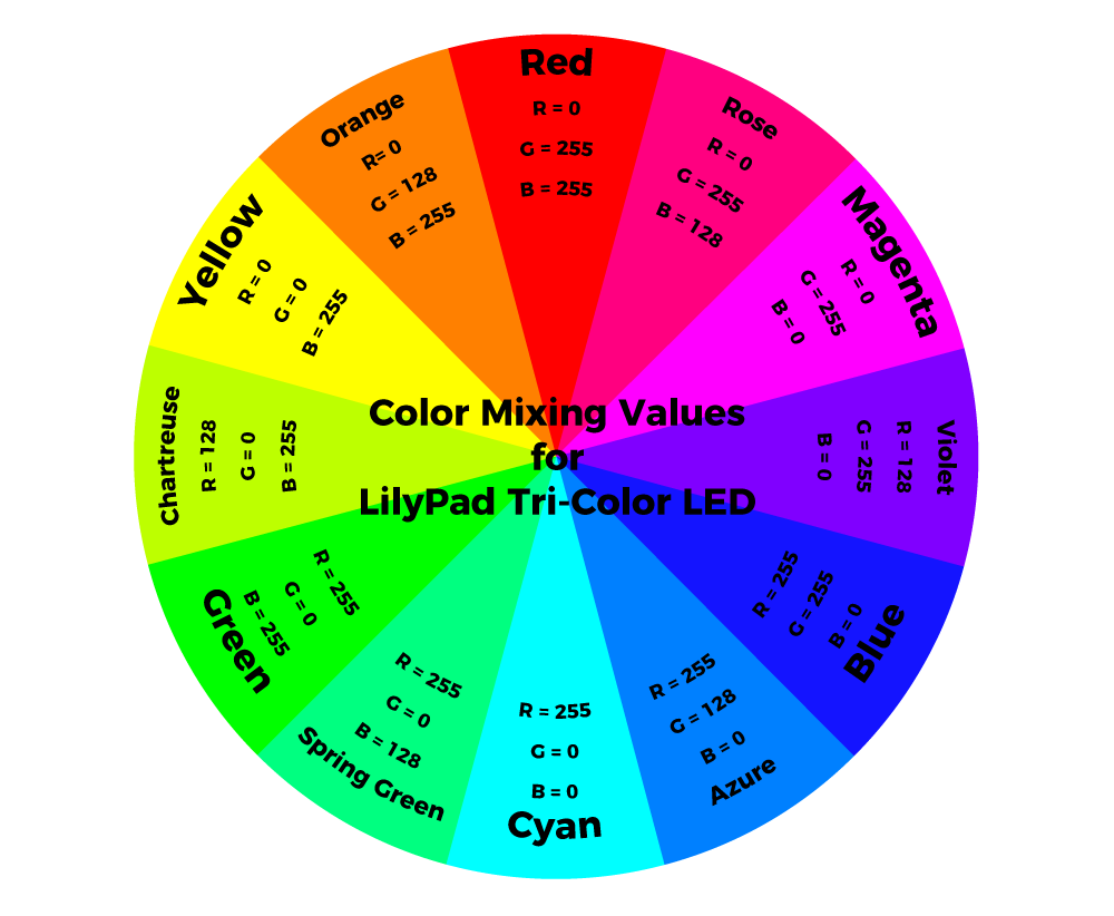
Understanding Your Program
Program Overview
- Display red:
R: 100%, G: 0%, B: 0%
Wait 1 second. - Display orange:
R: 100%, G: 50%, B: 0%
Wait 1 second. - Display yellow:
R: 100%, G: 100%, B: 0%
Wait 1 second. - Display chartruese:
R: 50%, G: 100%, B: 0%
Wait 1 second. - Display green:
R: 0%, G: 100%, B: 0%
Wait 1 second. - Display spring green:
R: 0%, G: 100%, B: 50%
Wait 1 second. - Display cyan:
R: 0%, G: 100%, B: 100%
Wait 1 second. - Display azure:
R: 0%, G: 50%, B: 100%
Wait 1 second. - Display blue:
R: 0%, G: 0%, B: 100%
Wait 1 second. - Display violet:
R: 50%, G: 0%, B: 100%
Wait 1 second. - Display magenta:
R: 100%, G: 0%, B: 100%
Wait 1 second. - Display rose:
R: 100%, G: 0%, B: 50%
Wait 1 second. - Repeat.
Code to Note
| Code | Description |
|---|---|
analogWrite(RGB_red,255);analogWrite(RGB_green,0);analogWrite(RGB_blue,0); |
Analog Write:Notice that likedigitalWrite(), the analog function takes two pieces of information - the pin it is controlling and a state to set that pin to. The analogWrite() function outputs a voltage between 0 and 3.3V on a pin, with this range divided into 255 steps, where digital output only had HIGH or LOW. This example uses three values to mix the rainbow of tertiary colors: 255 (OFF), 128 (50% brightness), and 0 (100% brightness). You can use any value between 0 and 255 when you begin to experiment with mixing your own colors. Note that for the tri-color LED, 0 turns the LEDs on and 255 turns them off. |
Coding Challenges
Try using a color picker to find the R, G, and B values for an interesting color and use that in your program. In order to translate them for use on the tri-color LED, you will need to do some math to reverse them.
Try creating your own rainbow light patterns using different values for the color mixes.
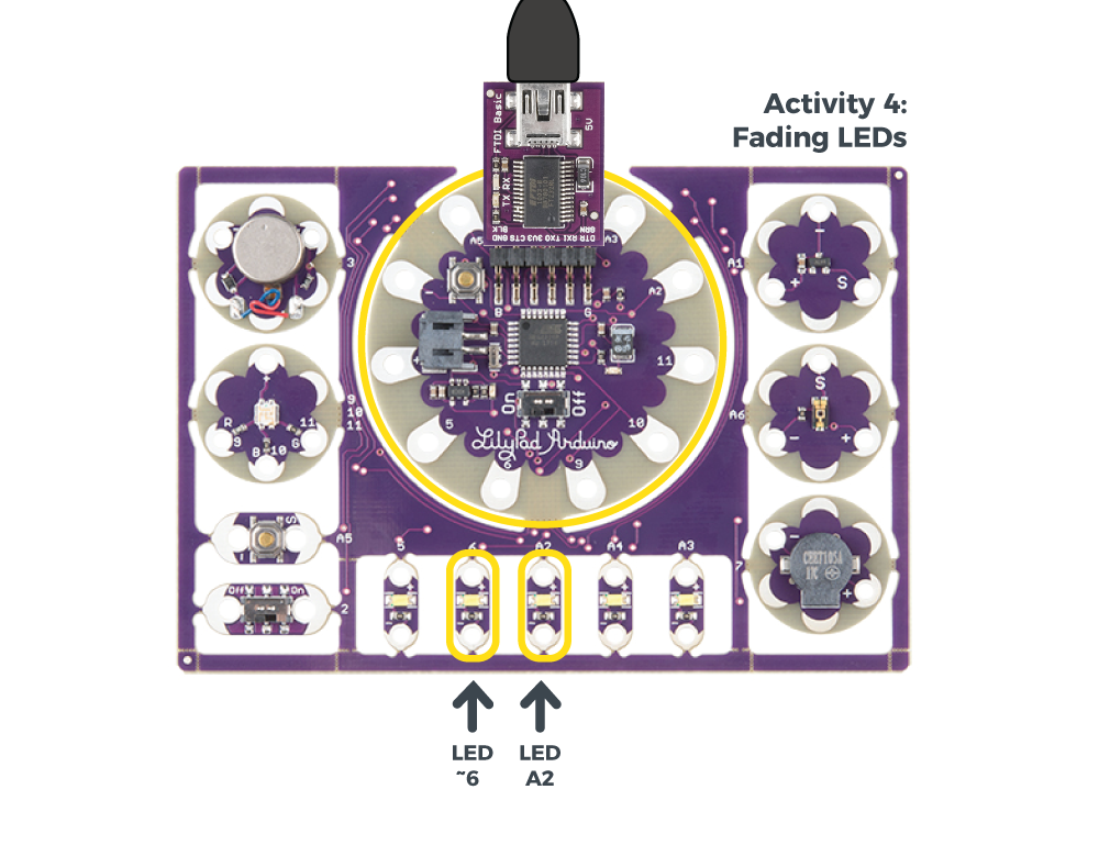
4: Fading LEDs
So far in these activities, we've controlled the brightness of LEDs manually. In this activity, you'll start letting the computer do the hard work. By using iteration (counting over a range of numbers), you can fade LEDs smoothly from off to on, a very nice effect you can use in your own projects.
LilyPad Boards Used in This Activity
- LilyPad Arduino Simple
- LilyPad LEDs
New Concepts Introduced in This Activity
Iteration Using For-Loops
We've already seen that the loop() function repeats forever. But there are many occasions in programming where you'll want the microcontroller to do something a certain number of times, or count up or down between two numbers. The for() loop is perfect for this.
In this example, we will use the for() loop to slowly increment the brightness of a LED from fully off to fully on, then do the same thing in reverse to turn it off. This creates a "fading" or "breathing" pattern that is great for art projects.
Example Code
To open the code, go to:
File > Examples > LilyPadDevelopmentBoard_ActivityGuide > LPD_04_Fading
You can also copy and paste the following code into the Arduino IDE. Hit upload, and see what happens!
language:c
/*
LilyPad Development Board Activity 4: Fading LEDs
SparkFun Electronics
https://www.sparkfun.com/products/11262

Use for-loops to smoothly vary the brightness of LEDs

Follow the tutorial at:
https://learn.sparkfun.com/tutorials/lilypad-development-board-activity-guide/4-fading-leds

This code is released under the MIT License (http://opensource.org/licenses/MIT)

******************************************************************************/

// In the previous activity we showed you how to manually change the brightness of a LED.
// In this activity we'll show you how to program the computer to do all the work.

// Create integer variables for the LED pins we'll be using:

int LED1 = 6;
int LED2 = A2;

void setup()
{
  // Set the LED pins to be outputs:

  pinMode(LED1, OUTPUT);
  pinMode(LED2, OUTPUT);
}

void loop()
{
  // The two "for loops" below will make a LED fade on and off in a "breathing" pattern.

  // Create a new integer variable called brightness:

  int brightness;

  // Now we'll have the program automatically change the value of brightness
  // using a command called "for".

  // for is like a tiny version of loop. The for command has several parts:
  // 1. something to do before starting (brightness = 0)
  // 2. a test to decide whether to keep going (brightness <= 255)
  // 3. a block of commands to run (everything within the {} below the for)
  // 4. a command to run before doing it again (brightness = brightness + 1)

  // Here's a for command which will start brightness at 0, check to see if it's less than
  // or equal to 255, run the commands after it, then add one to brightness and start over:

  for (brightness = 0; brightness <= 255; brightness = brightness + 1)
  {
    // Within the loop, we'll use brightnes variable to control the brigthness of the LEDs:

    analogWrite(LED1, brightness);
    analogWrite(LED2, brightness);

    // NOTE that not all pins work with analogWrite!
    // The ones with a "~" in front of them will change brightness,
    // the others will only turn on if brightness > 128.
    // Both types are used above, run the code and note the difference between them.

    // The delay command controls the speed - if you make the delay larger,
    // it will slow down the loop. Smaller, and it will run faster:

    delay(5);
  }

  // What if we want the LED to start at full brightness and fade to black?
  // We can easily set up the for loop to run in reverse:

  for (brightness = 255; brightness >= 0; brightness = brightness - 1)
  {
    analogWrite(LED1, brightness);
    analogWrite(LED2, brightness);
    delay(5);
  }
}
What You Should See
Once you upload the program, two of the white LEDs on the ProtoSnap will light up. The LED on 6 will fade smoothly on and off, while the LED on A2 will blink.
If you look at the code, both pins should be fading. This illustrates the difference between the sew tabs which can handle pulse-width modulation, and those that can't.
Understanding Your Program
Program Overview
- Set up the pins we'll be using
- Create a
for()loop that makes a variable iterate from 0 to 255 - Use that variable to fade the LEDs from off to on
- Create a
for()loop from makes a variable iterate from 255 to 0 - Use that variable to fade the LEDs from on to off
- Repeat
Code to Note
Iteration, or making variables change over time, is a very powerful tool in programming. Here we're using it to smoothly change the brightness of an LED using the analogWrite() command, but you can use it anywhere you want to do something a certain number of times, or you want to change a variable from one value to another in even steps.
Unlike other commands, the for() loop is set up using three statements, which we'll cover below. You'll use the same pattern often in your own programming.
| Code | Description |
|---|---|
for (brightness = 0; {analogWrite(LED1, brightness);analogWrite(LED2, brightness);delay(5);}
|
An Incrementing for() Loop:Here we're using afor() loop to increment the brightness variable from 0 to 255, running the set of commands within the brackets each time we change it. Let's walk through this code in detail:
|
for (brightness = 0;
|
Statements:Thefor() loop is set up a bit differently than other commands. It's controlled by three statements in parentheses after the command. Since these are statements and not parameters, they're separated by semicolons.
|
for (brightness = 0;
|
1. Set Up the Variable:1. The first statement runs before the counting starts, and is used to set up the variable you'll be counting with. Here we're setting thebrightness variable to zero, the number we're starting at.
|
for (brightness = 0;
|
2. Test Brightness Variable:The second statement is a test that thefor() loop uses to decide whether to keep counting. Here we're checking to see if brightness is less than or equal to 255. If the statement is true, the for loop will keep counting. If it's false, the loop will end.
|
for (brightness = 0; {analogWrite(LED1, brightness);analogWrite(LED2, brightness);delay(5);}
|
If True, Run CodeIf the test in the second statement is true, thefor() loop will run all of the commands included in the brackets after the for() command. This is where we're setting the brightness of the LED using the brightness variable. Remember to include a delay to slow things down a bit!
We've introduced a small bug into this program: we're using |
for (brightness = 0;
|
3. Change VariableAfter the commands in the brackets are run, the third statement will change the variable before starting the loop over again. Here we're incrementing thebrightness variable by one, but note that you can increment it by any amount, or even a negative value if you wish.
|
for (brightness = 255; {analogWrite(LED1, brightness);analogWrite(LED2, brightness);delay(5);}
|
A Decrementing for() Loop:Further down in the program, there's a secondfor() loop that decrements brightness from 255 to 0. Now that you know a little about for() loops, can you spot the differences that make this work?
|
Coding Challenges
Change the
delay()values to make the "pulsing" pattern go faster or slower.Try modifying the code to make other LEDs pulse.
Can you create a "heartbeat" pattern? (Two on-off pulses then a rest.)
5: Play a Tune
The microcontroller on the LilyPad Arduino Simple can turn its outputs on and off very quickly. If you carefully choose the frequency at which you're turning an output on and off, and send that signal to the buzzer on the LilyPad Development Board, you can create tones and simple musical tunes.
LilyPad Boards Used in This Activity
- LilyPad Arduino Simple
- LilyPad Buzzer
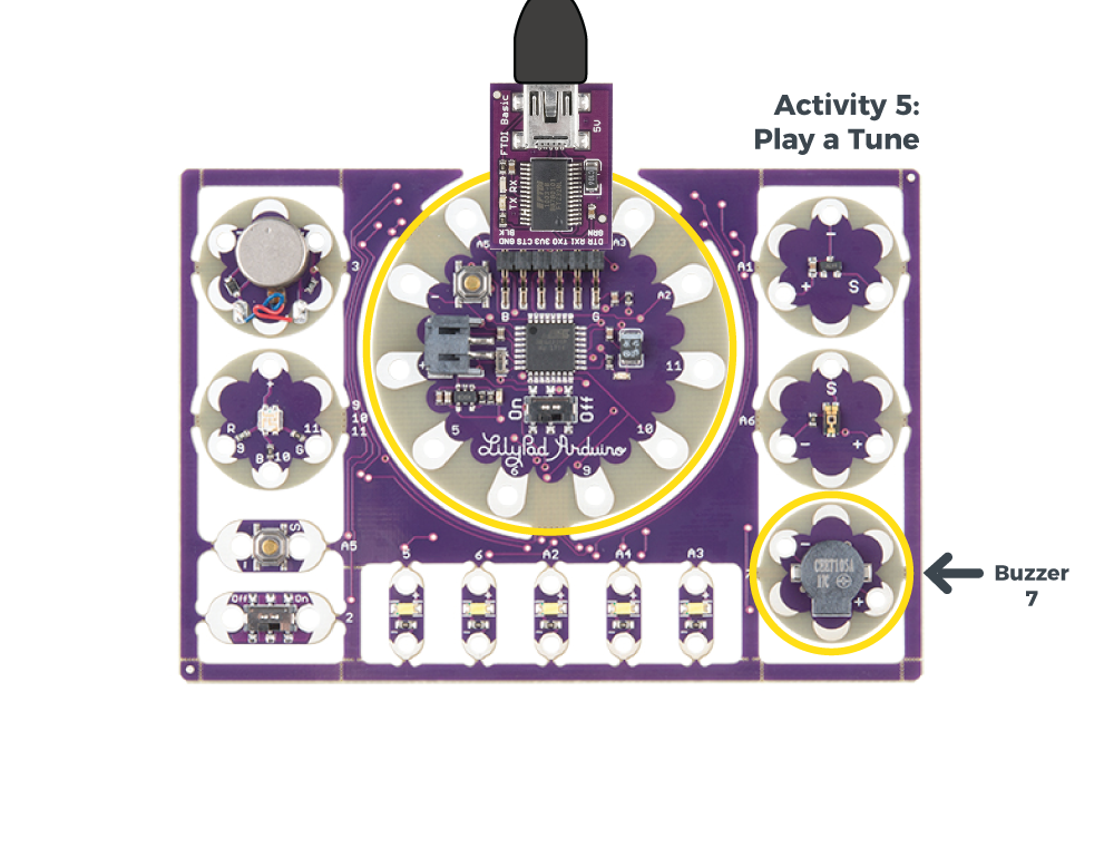
Inside the LilyPad Buzzer's plastic housing is a coil of wire and a small magnet. When current flows through this coil, it becomes magnetized and pulls towards the magnet, which makes a tiny “click”. When done thousands of times per second, the clicks create tones. In this activity, you’ll pulse the buzzer at specific frequencies to create musical notes. The buzzer can also be used to make alert sounds, robot beeps and boops, etc.
New Concepts Introduced in This Activity
Making Tones
You'll use the tone() and noTone() commands to drive the buzzer at specific frequencies.
A tone’s pitch is what we perceive when we think of a note as being very high (screams, forks scratching plates, etc.) versus very low (like earth-rumbling bass). The pitch of a tone is very closely related to the frequency played through a speaker. If we toggle a pin from HIGH-to-LOW then LOW-to-HIGH 440 times per second, for example, it produces a 440 Hz (hertz) frequency - a “middle A” pitch. Humans can hear frequencies ranging from 20 (low-pitch, bass) to 20,000 Hz (high-pitch, “ow, my ears”).
Example Code
To open the code, go to:
File > Examples > LilyPadDevelopmentBoard_ActivityGuide > LPD_05_Tune
You can also copy and paste the following code into the Arduino IDE. Hit upload, and see what happens!
language:c
/*
LilyPad Development Board Activity 5: Play a Tune
SparkFun Electronics
https://www.sparkfun.com/products/11262

Play musical notes through the buzzer on the LilyPad Development Board

Follow the tutorial at:
https://learn.sparkfun.com/tutorials/lilypad-development-board-activity-guide/5-play-a-tune

Uses frequencies from "melody" by Tom Igoe: https://www.arduino.cc/en/Tutorial/toneMelody

This code is released under the MIT License: (http://opensource.org/licenses/MIT)

******************************************************************************/

// Create an integer variable naming the pin we'll use for the buzzer.
// On the LilyPad Development Board, it's on 7.

int buzzer = 7;

// Map musical notes to their frequencies by creating variables for them.
// You can find the frequencies for higher and lower notes at:
// https://www.arduino.cc/en/Tutorial/toneMelody

int NOTE_C5 = 523;
int NOTE_CS5 = 554;
int NOTE_D5 = 587;
int NOTE_DS5 = 622;
int NOTE_E5 = 659;
int NOTE_F5 = 698;
int NOTE_FS5 = 740;
int NOTE_G5 = 784;
int NOTE_GS5 = 831;
int NOTE_A5 = 880;
int NOTE_AS5 = 932;
int NOTE_B5 = 988;
int NOTE_C6 = 1047;

// We'll also create a variable for how long to play each note in milliseconds.
// If you make this smaller, the notes will play faster.

int tempo = 500;

void setup()
{
  // Set the buzzer pin to be an output:

  pinMode(buzzer, OUTPUT);
}

void loop()
{
  // This code will play a simple scale from C5 to C6.

  // The tone command takes two parameters: a pin number and a frequency.
  // The tone will play until we stop it with the noTone command.
  // Each of the below blocks plays one note; the note plays during the delay command.

  tone(buzzer,NOTE_C5);
  delay(tempo);

  tone(buzzer,NOTE_D5);
  delay(tempo);

  tone(buzzer,NOTE_E5);
  delay(tempo);

  tone(buzzer,NOTE_F5);
  delay(tempo);

  tone(buzzer,NOTE_G5);
  delay(tempo);

  tone(buzzer,NOTE_A5);
  delay(tempo);

  tone(buzzer,NOTE_B5);
  delay(tempo);

  tone(buzzer,NOTE_C6);
  delay(tempo);

  // A longer delay at the end pauses the sound before looping again.
  // Here we're delaying four times the "tempo" value:

  noTone(buzzer);
  delay(tempo * 4);

  // Try writing your own song using the noted defined at the top of the program!
  // You can change the note duration by multiplying or dividing the "tempo" value
}
What You Should See
Once the code uploads, the buzzer will begin playing a simple musical scale over one octave, pause, and repeat.
Understanding Your Program
Program Overview
- Define variables for the audio frequencies we'll be using, and the tempo (speed at which we'll be playing).
- Configure the sew tab connected to the buzzer to be an output.
- Play a series of notes using the
tonecommand. - Pause and repeat.
Code to Note
| Code | Description |
|---|---|
int NOTE_C5 = 523;int NOTE_CS5 = 554;int NOTE_D5 = 587;int NOTE_DS5 = 622;int NOTE_E5 = 659;int NOTE_F5 = 698;int NOTE_FS5 = 740;int NOTE_G5 = 784;int NOTE_GS5 = 831;int NOTE_A5 = 880;int NOTE_AS5 = 932;int NOTE_B5 = 988;int NOTE_C6 = 1047; |
Frequency and Notes:To play a specific note you need to know its audio frequency (how fast the output needs to turn on and off). At the top of this program we've included variables for one octave (C5 to C6). These frequencies come from the Tone Melody tutorial on Arduino's site. If you want to play higher or lower notes you can find many more frequencies there. |
int tempo = 500; |
Setting Tempo:Another variable we've created is calledtempo. We'll use this to control the duration of all the notes, allowing you to change the speed of the tune from one place.
|
tone(buzzer,NOTE_C5); |
Making Tones:To actually make noise, we use thetone() command. It takes two parameters; the pin which has the buzzer attached to it, and the audio frequency to output.
|
tone(buzzer,NOTE_B5);delay(tempo); |
Setting Duration:Once you run thetone() command, the buzzer will keep making sound forever, even while the program continues on to other things. To control the duration of the tone, we'll use delay() along with our tempo variable to pause while the tone is playing.
|
tone(buzzer,NOTE_B5);delay(tempo);tone(buzzer,NOTE_C6);delay(tempo);noTone(buzzer); |
Changing and Stopping Sounds:To actually stop the tone, you can run anothertone() command with a different note, or use the noTone() command to turn off the sound. The noTone() command only needs one parameter, the pin number it is controlling. We use both methods in this program.
|
delay(tempo * 4); |
Pauses and Tempo:To pause before theloop() function repeats the scale, we're using another delay() at the end of the program. But to make it pause a bit longer, we multiply our tempo variable by four. This makes it pause for four times as long as each note plays. Half of music is the duration of the notes; you can use multiplication and division to turn individual notes into half notes, quarter notes, create rests, etc. Soon you'll be making real music!
|
Coding Challenges
This program plays a simple scale. Can you change the program to play an actual song?
In this program we used a variable called
tempoto change the durations of all the notes. In actual music, notes have different durations, and rests (periods of no sound) are important as well. Can you change the durations of individual notes by adding math to the delay values? Hint: Iftempois the duration of a whole note,tempo / 2would be the duration of a half note, etc.
6: Buttons and Switches
In the activities thus far, you have been using outputs - components that receive a signal or power from the LilyPad Arduino Simple and send information (light and sound) to the world. In the next few activities, we will start to receive input from the world using buttons and sensors to affect the LilyPad boards on the Development Board.
LilyPad Boards Used in This Activity
- LilyPad Arduino Simple
- LilyPad Button
- LilyPad Slide Switch
- LilyPad LEDs
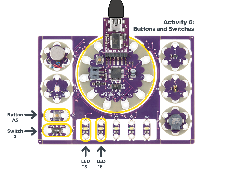
A switch is type of component that controls current flow in a circuit. The LilyPad Slide Switch is an example of a maintained switch, meaning its state remains the same until changed. The board has a small switch labeled ON/OFF; when the toggle is moved to the ON position, the two sew tabs on the switch are connected, allowing current to flow through and close the circuit. When moved to OFF, parts inside the switch move away from each other and open the circuit (disconnecting it).
What is a Button?
The LilyPad Button Board is a special type of switch called a momentary switch - it is only active when an action is applied. When you press the button in the middle of the board, it connects the two sew tabs and allows current to flow through. When you let go of the button, the connection is opened again, and the button springs back into place.
Learn more about how buttons and switches work and the different types you can use in Switch Basics.
New Concepts Introduced in This Activity
Digital Input
Just as digital outputs have two states, ON or OFF (HIGH or LOW in code), digital inputs also have two states. We'll use a special function called digitalRead() to check if the button has been pressed or if the switch has been flipped when attached to a sew tab on the LilyPad Arduino Simple.
Internal Pull-up Resistors
A pull-up resistor is a small circuit that holds the voltage HIGH (3.3V) on a pin until a button is pressed, pulling the voltage LOW (0V). The most common place you will see a pull-up resistor is when working with buttons. A pull-up resistor keeps the button in one state until it is pressed. The LilyPad Arduino Simple has built-in pull-up resistors, which we will use in code.
Variables for State Change
In Fading LEDs, the for() loop set a variable that was changed during the program. In this activity, you'll read the state of a button or switch to a variable to hold its state for later use in your program.
If Statements
In the Fading LEDs example, we explored a specialized function, the for() loop. In this activity, we'll use another function called an If Statement that will check if a state is true or false. Then we will make decisions based on the reading it receives. If/else functions are a way to start adding behavior based on input in your code, whereas the for() loop example created some automation. As you learn more specialized functions in Arduino (or write your own), your programs will become more complex and able to execute more complicated commands and interactions.
Example Code
To open the code, go to:
File > Examples > LilyPadDevelopmentBoard_ActivityGuide > LPD_06_Button
You can also copy and paste the following code into the Arduino IDE. Hit upload, and see what happens!
language:c
/*
LilyPad Development Board Activity 6: Buttons and Switches
SparkFun Electronics
https://www.sparkfun.com/products/11262

Explore digital input and program flow control using the button and switch

Follow the tutorial at:
https://learn.sparkfun.com/tutorials/lilypad-development-board-activity-guide/6-buttons-and-switches

This code is released under the MIT License (http://opensource.org/licenses/MIT)

******************************************************************************/

// Create integer variables for the pins we'll be using

int buttonPin = A5;
int switchPin = 2;

int buttonLED = 5;
int switchLED = 6;

void setup()
{
  // Initialize the button and switch pins as inputs with pullups.
  // Pullups keep the inputs from "floating" when a switch or button is open / unpressed.

  pinMode(buttonPin, INPUT_PULLUP);
  pinMode(switchPin, INPUT_PULLUP);

  // Initialize the LED pins as outputs:

  pinMode(buttonLED, OUTPUT);
  pinMode(switchLED, OUTPUT);
}

void loop()
{
  // This code will read the positions of the button and switch,
  // then use the "if" command to make LEDs follow these states.

  // Create variables to store the button and switch input values:

  int buttonState;
  int switchState;

  // Read and save the states of the button and switch:

  buttonState = digitalRead(buttonPin);
  switchState = digitalRead(switchPin);

  // The if-else statement lets you do different things based on different inputs:

  // The button will read as LOW when it's pressed

  if (buttonState == LOW) // Check to see if buttonState is LOW (pressed)
  {
    digitalWrite(buttonLED,HIGH); // If buttonState is LOW (pressed), turn on the LED
  }
  else
  {
    digitalWrite(buttonLED,LOW); // If buttonState is HIGH (unpressed), turn off the LED
  }

  if (switchState == LOW) // Check to see if switchState is LOW (switch is on)
  {
    digitalWrite(switchLED,HIGH); // If switchState is LOW (on), turn on the LED
  }
  else
  {
    digitalWrite(switchLED,LOW); // If switchState is HIGH (off), turn off the LED
  }
}
What You Should See
When you press the LilyPad Button, the LED connected to pin 5 will turn on. When the button is released, it will turn off. When you slide the LilyPad Slide Switch to the ON position, the LED connected to pin 6 will turn on and remain on until the switch is set to the OFF position.
Understanding Your Program
Program Overview
- Check to see if the button is pressed. a. If it is, turn buttonLED ON. b. If it isn’t, turn buttonLED OFF.
- Check to see if the switch is set to ON. a. If it is, turn switchLED ON. b. If it isn’t, turn switchLED OFF.
Code to Note
| Code | Description |
|---|---|
pinMode(buttonpin, INPUT_PULLUP);
pinMode(switchpin, INPUT_PULLUP);
|
Internal Pull-Up Resistor:In this program, we are setting the sew tab and pin attached to it as an input instead of output. However, with buttons and switches, they can give strange readings when disconnected electrically from a circuit (called 'floating'), so we'll use an internal pull-up resistor built into the LilyPad Arduino Simple, chosen by theINPUT_PULLUP option. |
int buttonstate;int switchstate; |
Variables to Store States:In Fading LEDs, we used a variable that changed over time in thefor() Loop, in this program we will use variables to store the state of the button and switch each time the program takes a reading with digitalRead(). |
buttonstate = digitalRead(buttonpin);switchstate = digitalRead(switchpin); |
Digital Input:Unlike the analog and digital output functions used in prior activities, the input functiondigitalRead() only needs one parameter - the pin it is checking. The function checks to see if an input pin is reading HIGH (3.3V) or LOW (0V). It returns a TRUE (1) or FALSE (0) depending on the reading.
This code uses the digital read function twice, once to check the state of the button and assign that value to the buttonstate variable and again to check the state of the switch and store that in the switchstate variable. |
if(logic statement) {code to be run if the logic statement is true}else {code to be run if the logic statement is false
} |
If/else Statements:Theif/else statement lets your code react to the world by running one set of code when a logic (conditional) statement in the round brackets is true and another set of code when the statement is false. For example, this example uses two if statements - one checks the button and turns the first LED on when pressed, and the second checks the switch and turns the second LED on when it is set to the ON position.Read more about if/else statments on Arduino Reference. |
buttonstate == LOWswitchstate == LOW |
Comparison Operators:In Arduino, the equals sign (=) is used to assign values. In situations where you want to compare two values, a comparison operator for 'is equal to' == is used. You can also use: != (not equal to)< (is less than)> (is greater than)<= (is less than or equal to)>= (is greater than or equal to) |
Coding Challenges
Can you adapt the code so that the opposite actions happen (when the button is pressed it turns the LED off and when the switch is off it sets the LED on)?
Try creating a light pattern that displays on the row of LilyPad LEDs when the switch is set to ON.
Can you adapt the Play a Tune example to include an on/off switch to control whether the song plays or not?
7: Sensing Light
This activity will also use inputs, this time to sense ambient light in the room and use that reading to light up LEDs. The light sensor is an analog sensor which provides a range of values instead of the digital ON/OFF of the buttons and switches example.
LilyPad Boards Used in This Activity
- LilyPad Arduino Simple
- LilyPad Light Sensor
- LilyPad LEDs
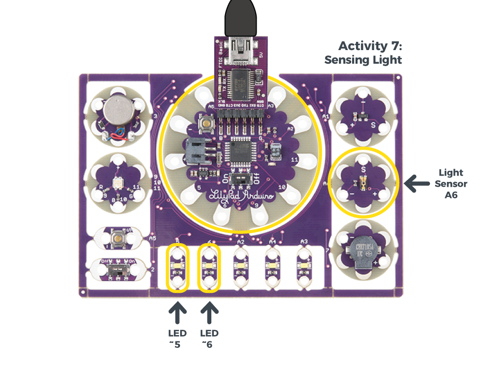
The LilyPad Light Sensor outputs voltage between 0V and 3.3V depending on the level of ambient light shining on it. Unlike the other LilyPad components you've used thus far, the light sensor has three sew tabs - positive, negative, and signal (S). The sensor is hooked up to power and ground tabs on the LilyPad Arduino Simple and the S tab is hooked up to a sew tab used for analog input.
As more light is applied on the sensor, more current will be able to flow from the board through the signal tab to your LilyPad Arduino Simple. If the sensor receives no light, no current will flow through it.
New Concepts Introduced in This Activity
Analog Input: Analog to Digital Conversion
In this activity, we’ll explore reading input from a sensor in a new way using analog input. Notice that certain sew tabs on the LilyPad Arduino Simple include an ‘A’ in front of the number - this indicates the pins on the controller and tabs that are connected have an Analog to Digital Converter (ADC). These pins can “sample” an analog signal being read by the controller and translate it to a digital signal that the controller can interpret.
In the last activity, we used digital inputs that read only two states. The LilyPad Light Sensor is an analog sensor, meaning it can read a wide range of values. For analog inputs, the values range from 0 (0V) to 1023 (3.3V).
Serial Monitor and Serial Commands
When using the button and switch, it was pretty easy to tie the ON/OFF to an LED turning ON/OFF. For sensors reading a range of values, it is more useful to actually see those numbers and make decisions using them. The Serial Monitor and Serial Commands are useful tools for displaying information from variables or other debugging tools for your code.
Example Code
To open the code, go to:
File > Examples > LilyPadDevelopmentBoard_ActivityGuide > LPD_07_Light
You can also copy and paste the following code into the Arduino IDE. Hit upload, and see what happens!
language:c
/*
LilyPad Development Board Activity 7: Sensing Light
SparkFun Electronics
https://www.sparkfun.com/products/11262

Explore analog input from the light sensor

Follow the tutorial at:
https://learn.sparkfun.com/tutorials/lilypad-development-board-activity-guide/7-sensing-light

This code is released under the MIT License (http://opensource.org/licenses/MIT)

******************************************************************************/

// Create variables for the pins we'll use:

int sensorPin = A6;

int LED1 = 5;
int LED2 = 6;

void setup()
{
  // Initialize the sensor pin as an input, but without a pullup
  // (Pullups are only used for switch inputs)

  pinMode(sensorPin, INPUT);

  // Initialize the output pins:

  pinMode(LED1, OUTPUT);
  pinMode(LED2, OUTPUT);

  // Initialize the serial monitor:

  Serial.begin(9600);
}

void loop()
{
  int sensorValue;

  // Read the sensor value (will be 0 to 1023):

  sensorValue = analogRead(sensorPin);

  // Print out the sensor reading to the serial monitor:

  Serial.print("sensor value: ");
  Serial.println(sensorValue);

  // Since the sensor value is 0 to 1023,
  // and analogWrite needs a value from 0 to 255,
  // we'll divide the sensor value by four to scale it down:

  analogWrite(LED1,sensorValue / 4);
  analogWrite(LED2,sensorValue / 4);
}
What You Should See
Hold your hand over the light sensor to change the amount of light it is exposed to and observe the LilyPad LEDs. As the light sensor reads less light, the LEDs will reflect the light levels with their brightness levels. You can also use a flashlight to shine more light on the sensor and observe how it affects the LEDs.
Understanding Your Program
Program Overview
- Store the light level in the variable
sensorValue. - Print the reading to the Serial Monitor.
- Set the brightness level of the LEDs to the number stored in the sensorValue variable divided by 4.
- Repeat.
Using the Serial Monitor:
The Serial Monitor is one of the Arduino IDE's many great built-in tools. It can help you understand the values that your program is trying to work with, and it can be a powerful debugging tool when you run into issues where your code is not behaving the way you expected it to. In this activity, you will use the Serial Monitor to print the values from the light sensor to it and observe how they change as the ambient light changes. To see these values, click the Serial Monitor button indicated by the magnifying glass icon in the upper-right corner of the IDE. You can also select Tools > Serial Monitor from the menu.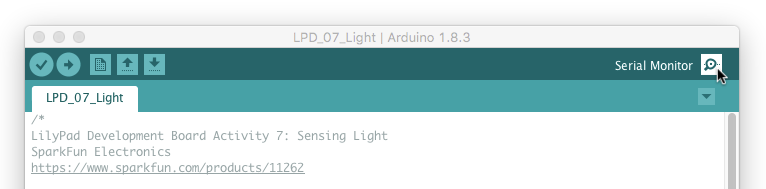
A new window will pop up where you should then see numeric values appear. Cover the light sensor, and you should see the values change as they scroll by.
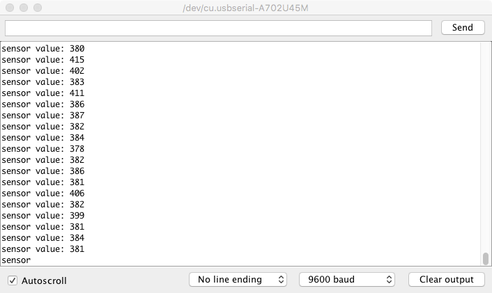
The values on your screen may look different than in this image. The range of readings will depend on the light levels in the room you are working in.
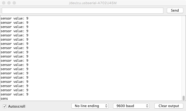
If you are having trouble seeing the values, double check that 9600 baud is selected in the dropdown menu at the bottom right of the window and the auto scroll option is checked.
Code to Note
| Code | Description |
|---|---|
pinMode(sensorPin, INPUT); |
Setting Input:When using analog sensors, you do not need to use anINPUT similar to what you did in the buttons and switches activity. |
Serial.begin(9600); |
Serial Begin:In this program, you will use the Serial Monitor. In order to see anything displayed in the monitor, you must start a serial connection with your LilyPad Arduino Simple by usingSerial.begin(). This allows the LilyPad Arduino Simple to send and receive data to your computer. The number 9600 is the communication speed between the devices, called baud rate. The baud rate must match in both your code and the drop down menu in the Serial Monitor. |
sensorValue = analogRead(sensorpin); |
Analog Input:Similar to how you checked for a button or switch state in the last activity, theanalogRead() function reads the value on a pin attached to an analog sensor. In this code the pin is defined as the sensorPin. Unlike digitalRead(), which returns one of two states (HIGH/LOW), this function returns a number between 0 (0 volts) and 1023 (3.3V volts), which is then assigned to the variable sensorValue. |
Serial.print("sensor value: ");Serial.println(sensorValue); |
Serial Print Commands:After opening the communication to the Serial Monitor in setup, you can now send some values to it. The first line prints some descriptive text to the monitor, and the second prints the value stored insensorValue. The ln at the end of print tells the monitor to print a new line at the end of each value; otherwise the values would all run together on one line. Try removing the ln to see what happens.Learn more about the Serial Print commands in the Arduino Reference. |
analogWrite(LED1,sensorValue / 4);analogWrite(LED2,sensorValue / 4);
|
Adjust Brightness:These lines of code use thesensorValue variable to set the brightness of the two LEDs. However, remember from the color mixing and fading examples that the analogWrite() can only take a value between 0 and 255, while the sensor will provide values up to four times that number. To get a number the function can use, the program divides the range by 4. |
Coding Challenges
Can you change the code so that the tri-color LED displays a brighter or dimmer white when the light levels change?
Can you change the code so that two colors mix on the tri-color LED when the light levels change?
Can you create a blink pattern where the speed of the blink is determined by the light sensor readings?
8: LED Bar Graph
The LilyPad Development Board includes five pre-wired white LEDs, because they're in a row they're perfect for creating a LED bar graphs. In this activity, we'll experiment with graphing the readings from the light sensor onto the row of LEDs.
LilyPad Boards Used in This Activity
- LilyPad Arduino Simple
- LilyPad Light Sensor
- LilyPad LEDs
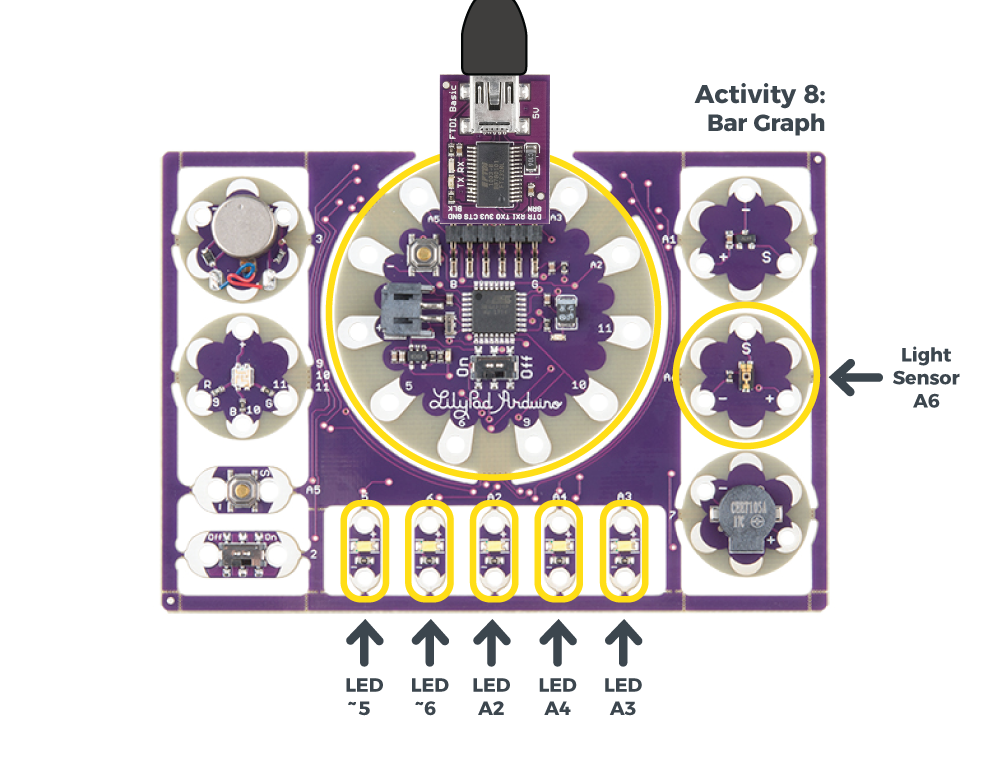
An LED bar graph is a row of LEDs that you can use to display information by lighting up one or more of the LEDs. The LilyPad Development Board has a row of LEDs you can use as a bar graph. LED bar graphs have less resolution than other types of displays, but this can be an advantage if you just need a quick indication if a value is high or low.
New Concepts Introduced in This Activity
Using Arrays
Arrays are a handy way to store many variables in one structure. Here we'll store the pin / sew tab numbers of the white LEDs, making them easier to use as a group.
Creating Custom Functions
So far we've been using Arduino's built-in functions, but you can also create your own. Functions are great for bits of code you want to run repeatedly, or even reuse in other programs.
Anatomy of a Function
So far we've been using Arduino's built-in functions to do everything, but you can write your own functions as well. Functions are a great way to encapsulate a bit of code that you use a lot, or want to re-use in other programs.You've already seen the basic structure of the
setup() and loop() functions. Your own functions will have the same structure. Let's go over the individual pieces:
Return Type
You've probably noticed the word
void at the start of the setup() and loop() functions, and wondered what that means.
Functions can optionally return values, and the return type lets you specify what type of data it will be returning. Some functions, like
setup() and loop() just carry out that task. Since they don't return a value, their return type is void.
Other functions, like
digitalRead() and analogRead() return a value. These functions have int as their return type.
If you want to write a function that returns a value, specify the return type (usually
int) before the name, and include a return statement at the end of the function. Here's an example of a very simple function that always returns 4 when called:
int four(){ return 4;} |
Name
Every function needs a name. It should be unique; not the name of an existing function or variable (you can tell this if the name changes color when you type it in). Ideally the name should be descriptive of what the function does, though of course it's your program and you can name things whatever you wish.
Parameters
You've seen that many functions require parameters. For example,
pinMode() requires a pin number, and whether that pin should be configured as an INPUT or OUTPUT.
If your custom function needs parameters, you can declare them in the parentheses after the function name. These are declared just like variables in our code; with a type (usually
int) and a name. If you need more than one parameter, separate the declarations with commas. Here's an example of a simple function that adds two numbers together and returns the result:
int add(int a, int b){ int c; c = a + b; return c;}Note that when you call a function with parameters, the values are transferred to the function by position, not by name. Let's say you're calling your
add functions from the main loop:
var1 = 100;var2 = 200;var3 = add(var1,var2);When your
add() function runs, the variable a will get the value 100 from var1, and the variable b will get the value 200 from var2. When the function returns, it will transfer the value from c back to var3 (which will be 300).
Scope
Now's a good time to bring up the concept of scope, which governs where variables are visible in your program (spoiler: it depends on where you declare them.)
In all of our activities, we've declared several variables at the very top of the program. Because they are declared "outside" of
setup() and loop(), they've visible within those functions (and any others you create). Because these variables are visible everywhere, they're called global variables.
We can also declare variables inside functions, as we did in the
add() function above. This variable will be usable within the function, but if you try to access it elsewhere, you will get an error ("variable not declared in this scope"). These are called local variables.
Both types of variables have their place. Global variables are useful for pin names and option settings, since they're visible everywhere and easy to change from one place. Local variables are ideal for data that doesn't need to leave a function; they allow you to copy and paste functions to new programs.
Learn more about functions and their use at the Arduino Reference site.
Incrementing Shortcuts
Many times in programming you'll want to add or subtract one from a number, such as in a for() loop. In earlier activities, we did this with the pattern x = x + 1. But there are some handy shortcuts you can use:
| The Long Way | Shortcut |
|---|---|
| x = x + 1 | x++ |
| x = x - 1 | x-- |
| x = x + 5 | x += 5 |
| x = x - 8 | x -= 8 |
| x = x * 2 | x *= 2 |
| x = x / 4 | x /= 4 |
Learn more about compound operators for shorcuts and their use at the Arduino Reference site.
Example Code
To open the code, go to:
File > Examples > LilyPadDevelopmentBoard_ActivityGuide > LPD_08_BarGraph
You can also copy and paste the following code into the Arduino IDE. Hit upload, and see what happens!
language:c
/*
LilyPad Development Board Activity 8: LED Bar Graph
SparkFun Electronics
https://www.sparkfun.com/products/11262

Play with the row of five LEDs on the bottom of the LilyPad Development Board

Follow the tutorial at:
https://learn.sparkfun.com/tutorials/lilypad-development-board-activity-guide/8-led-bar-graph

This code is released under the MIT License (http://opensource.org/licenses/MIT)

******************************************************************************/

// Create a variable for the light sensor input:

int sensorPin = A6;


// To the five LEDs on the LilyPad Development Board easier to use, we'll put those numbers into an array.
// The initial [5] defines the size of the array (five elements).
// We're filling the array with predefined values, but you could do this
// in your code as well.

int bargraphLED[5] = {5,6,A2,A4,A3};

// The array is indexed from 0 to 4; for example bargraphLED[2] = A2

void setup()
{
  int x;

  // Initialize the sensor pin as an input, but without a pullup
  // (Pullups are only used for switch inputs)

  pinMode(sensorPin, INPUT);

  // Initialize the bargraph LED pins as outputs
  // We'll use the matrix we defined above,
  // where the LEDs are indexed from 0 to 4

  for (x = 0; x <= 4; x++)
  {
    pinMode(bargraphLED[x], OUTPUT);
  }

  // Initialize the serial monitor

  Serial.begin(9600);
}

void loop()
{
  int sensorValue;

  // Read the sensor value (will be 0 to 1023):

  sensorValue = analogRead(sensorPin);

  // Print out the sensor reading:

  Serial.print("sensor value: ");
  Serial.println(sensorValue);

  // Display the sensor reading on the bar graph LEDs.
  // This is a new function that we created ourselves (see below).

  barGraph(sensorValue);
}

// Here we're making our own command called barGraph:
// The first "void" means we don't return anything from this command
// The "int value" is what we'll pass to the command (it must be an integer,
// and it will be called "value" in the command.

void barGraph(int value)
{
  // Create a LED bargraph using value as an input.
  // Value should be in the range 0 to 1023.

  int x;

  // Step through the bargraph LEDs,
  // Turn them on or off depending on value.

  // Value will be in the range 0 to 1023.
  // There are 6 LEDs in the bargraph.
  // 1023 divided by 5 is 204, so 204 will be our threshold
  // between each LED

  for (x=0; x <= 4; x++)
  {
    if (value > (x*204) )
    {
      digitalWrite(bargraphLED[x], HIGH);
    }
    else
    {
      digitalWrite(bargraphLED[x], LOW);
    }
  }
}
What You Should See
After the code loads, the row of white LEDs on the LilyPad Development Board will create a bar graphing showing how much light is hitting the light sensor by lighting up more or less of the row. Try covering the sensor with your hand, or aiming a flashlight at it to see a larger or smaller response from the bar graph.
Understanding Your Program
Program Overview
- Set up an array with the white LED pins.
- Configure the pins and serial monitor.
- Read the light level.
- Display it on the bar graph.
- Repeat.
Code to Note
| Code | Description |
|---|---|
int bargraphLED[5] = {5,6,A2,A4,A3}; |
Creating an Array:An array is a convenient way to group a number of variables together. Here we're taking the pin numbers of the white LEDs, and storing them in an array calledbargraphLED.
When you declare an array, one method is to specify how many variables (also called elements) it will contain. This array will contain five variables, which we specify in brackets after the variable name. At the same time that we're declaring the array, we're also filling it in with our LED pin numbers. Later on, if you want to read or write one of those variables, you specify it by position. The positions in this array are numbered 0 through 4. For example, if you want to reference the variable in position 2, you would write bargraphLED[2], which equals A2.
|
for (x = 0; x <= 4; x++){ pinMode(bargraphLED[x], OUTPUT);} |
Using an Array:The nice thing about storing our bar graph LEDs in an array is that we can access the pin numbers by their positions (0 to 4). This makes it easy to createfor() loops that do the same thing to all of them, like using pinMode() to make them all outputs.
|
void barGraph(int value){ int x; for (x=0; x <= 4; x++) { if (value > (x*204) ) { digitalWrite(bargraphLED[x], HIGH); } else { digitalWrite(bargraphLED[x], LOW); } }} |
Creating a Custom Function:In addition to the standard functionssetup() and loop(), you can create your own functions. Here we've created a new function called barGraph(). It's set up much like the setup() and loop() functions, but we've added a parameter called value. The value should be from 0 to 1023, the same range we get from analogRead().
Within the brackets of our function, we step through the positions in our LED array (0 to 4). We then determine whether each LED should be lit up or not. Each LED represents about 204 in the range of 0 to 1023, and if |
barGraph(sensorValue);
|
Using a Custom Function:Now that we've written our custom function, we can use it insidesetup() or loop() just like any other command. As you recall, we wrote barGraph() to take one parameter. Here we're providing it with sensorValue. This value will be transferred to the value variable within the function itself.
|
Coding Challenges
Alter the function of the bar graph so that all of the LEDs are on, and go out as the value increases.
Alter the value of the bar graph so that it fills in from the right rather than from the left. Hint: Can you do this by declaring the array differently?
9: Theremin Project
Now that you've explored the basic programming skills needed to use the Development Board, it's time to start combining some of those skills into more interactive projects. The first project we'll explore is creating a musical 'instrument' inspired by a theremin. A theremin is an instrument played without needing physical contact, typically utilizing antennas. In this 'theremin', you'll use readings from the light sensor as a controller for frequency of tones produced by the buzzer. We can further categorize this project an opto-theremin because it is using light as a controller. In addition to the sensor and buzzer, we'll display the light readings on the bar graph and add the button as an on/off trigger.
LilyPad Boards Used in This Activity
- LilyPad Arduino Simple
- LilyPad Light Sensor
- LilyPad Buzzer
- LilyPad Button
- LilyPad LEDs
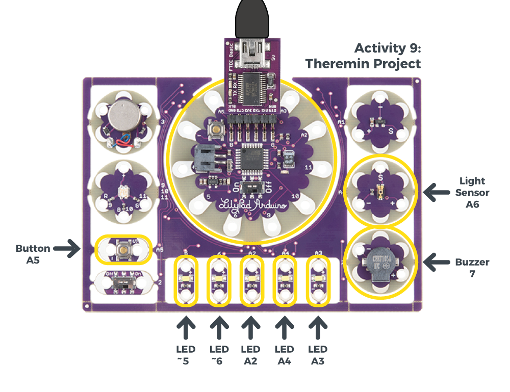
New Concepts Introduced in This Activity
Using the Map() Function
The map() function is a handy function that translates one range of numbers into another range.
For example, let's say you wanted to use the light sensor (read by analogRead()) to control the brightness of a LED (written by analogWrite()), as we did back in activity 7. But the range of analogRead() (0 to 1023) doesn't match the range of analogWrite() (0 to 255).
This particular example is easy to solve in that you can simply divide the light sensor value by 4, as we did in activity 7. But it would take a bit more work to solve for arbitrary ranges that may not start at 0, as we'll be doing in this activity.
The map() function does this for you. The parameters it needs are:
result = map(value,fromLow,fromHigh,toLow,toHigh);
Where fromLow to fromHigh is the range of the original value, and toLow to toHigh is the range we want to translate that value into.
For example, here's how we'd set up map() for our earlier example:
LEDbrightness = map(lightSensorValue,0,1023,0,255);
It's worth mentioning that if value isn't within the original range, map() will still work; but it will return a result outside the target range. If your result must be within the target range, an additional function called constrain() can be used to ensure that:
result = constrain(value,low,high);
If value is already within the range of low to high, the result will be the same as value. But if value is outside that range, it will be set to low or high, whichever is closest. Our complete example would then look like:
LEDbrightness = map(lightSensorValue,0,1023,0,255);
LEDbrightness = constrain(LEDbrightness,0,255);
Example Code
To open the code, go to:
File > Examples > LilyPadDevelopmentBoard_ActivityGuide > LPD_09_Theremin
You can also copy and paste the following code into the Arduino IDE. Hit upload, and see what happens!
language:c
/*
LilyPad Development Board Activity 9: Theremin
SparkFun Electronics
https://www.sparkfun.com/products/11262

A Theremin is an electronic musical instrument that is played by
moving your hands over it. In this activity we'll create a Theremin
using the light sensor and the buzzer.

Follow the tutorial at:
https://learn.sparkfun.com/tutorials/lilypad-development-board-activity-guide/9-theremin-project

This code is released under the MIT License (http://opensource.org/licenses/MIT)

******************************************************************************/

// Create variables for the pins we'll be using

int sensorPin = A6;
int buttonPin = A5;
int buzzer = 7;
int bargraphLED[5] = {5,6,A2,A4,A3};

// Set the highest and lowest frequencies
// (Change these and see what happens)

int highestFrequency = 1047; // C6
int lowestFrequency = 523; // C5

void setup()
{
  int x;

  // Initialize the pins we'll be using

  pinMode(sensorPin, INPUT);
  pinMode(buzzer, OUTPUT);
  pinMode(buttonPin, INPUT_PULLUP);

  for (x = 0; x <= 4; x++)
  {
    pinMode(bargraphLED[x],OUTPUT);
  }

  // Initialize the serial monitor

  Serial.begin(9600);
}

void loop()
{
  int sensorValue;
  int frequency;

  // Read the sensor value (will be 0 to 255):

  sensorValue = analogRead(sensorPin);

  // Print out the sensor reading:

  Serial.print("sensor value: ");
  Serial.println(sensorValue);

  // Display the sensor reading on the bar graph LEDs:

  barGraph(sensorValue);

  // Play a tone based on the light level:

  // The light sensor will return a value from 0 to 1023,
  // but we want to map this to a specific range of frequencies.
  // We'll use a built-in fuction called "map" that transforms one range
  // of values (0 to 1023) to another (lowestFrequency to highestFrequency):

  frequency = map(sensorValue,0,1023,lowestFrequency,highestFrequency);

  if (digitalRead(buttonPin) == LOW) // If the button is pressed:
  {
    tone(buzzer,frequency);
  }
  else
  {
    noTone(buzzer);
  }
}

void barGraph(int value)
{
  // Create a LED bargraph using value as an input.
  // Value should be in the range 0 to 1023.

  int x;

  // Step through the bargraph LEDs,
  // Turn them on or off depending on value.

  // Value will be in the range 0 to 1023.
  // There are 6 LEDs in the bargraph.
  // 1023 divided by 5 is 204, so 204 will be our threshold
  // between each LED (0,42,84, etc.)

  for (x=0; x <= 4; x++)
  {
    if (value > (x*170) )
    {
      digitalWrite(bargraphLED[x], HIGH);
    }
    else
    {
      digitalWrite(bargraphLED[x], LOW);
    }
  }
}
What You Should See
To play the theremin, press and hold the button with one hand and cover the light sensor with the other. As the light sensor reads different light levels, the frequency on the buzzer will change and the row of LEDs will illuminate to show the different tones. Release the button to stop the sounds. You can also use a flashlight to shine more light on the sensor and get a large range of tones.
Understanding Your Program
Program Overview
- Create variables to store.
- Read the value from the light sensor and store in
sensorValue. - Print the light sensor reading to the serial monitor.
- Display the sensor reading on the bar graph using a custom
barGraph()function. - Map the values from the light sensor to the set range of frequencies (set in
lowestFrequencyandhighestFrequency) - Check to see if the button is pressed.
a. If it is, send a
tone()command to the buzzer using thefrequencyvalue. b. If it is not, turn the buzzer off usingnoTone()command. - Repeat.
Code to Note
| Code | Description |
|---|---|
map(value,inMin, inMax, outMin, outMax) |
Mapping a Range of Values:Themap() function is a tool in Arduino used to take a value from one range and constrain it to another. This is especially helpful when you want to take readings from an analog input (which can range from 0-1023) and use them to display directly on an output (which ranges from 0-255). In previous examples, the code used division to make these two variables compatible. The map function is a little more sophisticated. The map value has five parameters, listed below:Value: sensorValue The values/variable to map. In this code we are using the data we read from the light sensor stored in sensorValue.inMin: 0 inMax: 1023 The minimum and maximum bounds of the value to be mapped. In this case, since sensorValue is from an analog sensor, these will be 0-1023.
outMin: lowestFrequencyoutMax: highestFrequencyThe minimum and maximum bounds you want to map the current value to. In this case, we've chosen a range of frequencies stored in the lowestFrequency and highestFrequency variables set at the beginning of the program.
Read more about the map() function on the Arduino Reference site. |
Coding Challenges
Adjust
lowestFrequencyandhighestFrequencyto use different ranges for the tones the theremin creates.Try adding additional sound controls by adding another
if/elsestatement using the switch. Suggestions: Turning a light pattern on/off that coordinates with the sound or switching between different frequency ranges.
10: Twinkling Night-Light Project
In this activity, we'll pull together elements from earlier activities to create an entire project: a night-light that randomly twinkles LEDs when it gets dark. You could use this as the starting point for a project based around twinkling stars, fireflies, lightning clouds or something else entirely.
LilyPad Boards Used in This Activity
- LilyPad Arduino Simple
- LilyPad Tri-Color LED
- LilyPad Light Sensor
- LilyPad LEDs
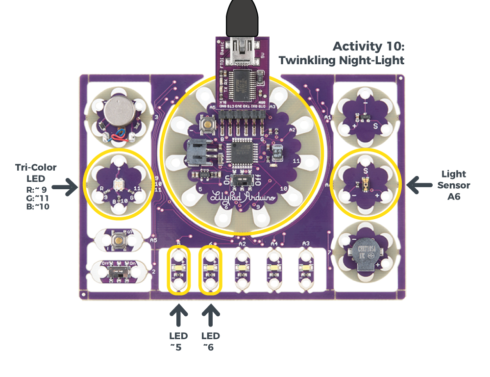
New Concepts Introduced in This Activity
Random
Computers are generally very predictable. Usually this is exactly what we want, but sometimes, especially when creating artistic projects, we want a bit of randomness to make things more surprising and natural. In this activity, we'll introduce the random() command, which will help you do exactly that.
The random() function is a fun command that will return a random number. You can use it to randomize which LEDs are lit, how long to pause, what tone to play, etc. The random() function takes one parameter, the number of possibilites to choose from. For example, if you wanted to simulate a six-sided die, you would call random(6). The function will then return a number between 0 and 5.
The numbers returned by
random() aren't entirely random. Every time your program runs, it will repeat the same "random" sequence. This is good enough for many art projects, but if you want a truly random sequence each time your program runs, you can use the randomSeed() command. See Arduino's Reference site for more information on how to use random() in your code.
Setting a Threshold
To determine when it's dark enough to begin twinkling, we'll define a threshold value. If the ambient light level is below that value, we'll begin twinkling. To help you fine-tune this value, we also use the serial monitor to print out the current light level.
Example Code
To open the code, go to:
File > Examples > LilyPadDevelopmentBoard_ActivityGuide > LPD_10_NightLight
You can also copy and paste the following code into the Arduino IDE. Hit upload, and see what happens!
language:c
/*
LilyPad Development Board Activity 10: Twinkling Night-Light
SparkFun Electronics
https://www.sparkfun.com/products/11262

Create a twinkling night-light that turns on when it gets dark.

Follow the tutorial at:
https://learn.sparkfun.com/tutorials/lilypad-development-board-activity-guide/10-twinkling-night-light-project

This code is released under the MIT License (http://opensource.org/licenses/MIT)

******************************************************************************/

// Create variables for the pins we'll be using:

int lightSensor = A6;

// Array of all the LEDs we'll be twinkling. You can set these to the sewtabs
// you'll be using in your project. Remember to only choose outputs that
// have the "~" symbol that are compatible with analogWrite.

int numLEDs = 2;
int LED[2] = {5,6};

int blueLED = 10;

// Threshold for light level (when it's darker than this, twinkle LEDs)

int threshold = 50;

void setup()
{
  int x;

  // Initialize the pins we'll be using

  pinMode(lightSensor, INPUT);

  for (x = 0; x < numLEDs; x++)
  {
    pinMode(LED[x],OUTPUT);
  }

  pinMode(blueLED,OUTPUT);

  // Initialize the serial monitor

  Serial.begin(9600);
}

void loop()
{
  int x,lightLevel,brightness;

  // Read the sensor value (will be 0 to 255):

  lightLevel = analogRead(lightSensor);

  // Print out the sensor reading:

  Serial.print("light level: ");
  Serial.print(lightLevel);
  Serial.print(" threshold: ");
  Serial.print(threshold);
  Serial.print(" twinkle: ");

  // If the light level is below the threshold, twinkle LEDs:

  if (lightLevel < threshold)
  {
    Serial.println("ON");
    digitalWrite(blueLED,LOW); //Note that this is reversed than other LEDS because the tri-color LED is common anode.

    // Pick a random LED:

    x = random(numLEDs);

    // Quickly ramp up the brightness of the LED from off to on:

    for (brightness = 0; brightness <= 255; brightness++)
    {
      analogWrite(LED[x],brightness);
      delay(1);
    }

    // Quickly ramp down the brightness of the LED from on to off:

    for (brightness = 255; brightness >= 0; brightness--)
    {
      analogWrite(LED[x],brightness);
      delay(1);
    }

    // Wait a random amount of time (up to 2 seconds)

    delay(random(2000));
  }
  else
  {
    Serial.println("off");
    digitalWrite(blueLED,HIGH); //Note that this is reversed than other LEDS because the tri-color LED is common anode.
  }
}
What You Should See
Cover the light sensor with your hand. When the sensor's readings drop below the set threshold, the tri-color LED's blue LED will light up indicating it is 'dark'. Then two LEDs along the bottom of the Development Board will twinkle in a random pattern.
Understanding Your Program
Program Overview
- Set up our array with the LEDs we want to twinkle.
- Set up our input and output pins.
- Read the light sensor value; if it's low, turn on the blue LED and begin twinkling.
- To twinkle, choose a random LED from the array, then rapidly brighten and dim it.
- Wait a random amount of time between twinkles.
- Repeat.
Code to Note
| Code | Description |
|---|---|
int x,lightLevel,brightness; |
Declaring Multiple Variables Shortcut:In this program, instead of creating a line for each variable declaration, we combined them into one statement. Since all three of the variables you will use are the same typeint, they can be declared together. |
int numLEDs = 2;int LED[2] = {5,6}; |
Using Arrays:As in the bar graph activity, we're creating an array calledLED with the list of LEDs we'd like to twinkle. Note that these are all PWM-capable pins (the ones with the "~" symbol). Because there could be a few or many LEDs in this list, we're also saving the number of LEDs we'll be using in numLEDs. |
int threshold = 50; |
Setting a Threshold Variable:In this program, we'll be creating a night-light that only twinkles when the ambient light level is below a certain threshold. You can fine-tune this value using the information printed in the serial monitor. |
lightLevel = analogRead(lightSensor);...if (lightLevel < threshold){ ... |
Check Light Levels Against Threshold:In theloop()function, the first thing we do is check the ambient light level. If it's below the threshold value, we start twinkling.
|
x = random(numLEDs); |
Choose a Random LED:First we pick which LED we'd like to twinkle. Therandom function will choose a number between 0 and numLEDs. We'll use this number as an index into the LED array.
|
for (brightness = 0; brightness <= 255; brightness++){ analogWrite(LED[x],brightness); delay(1);}
|
Creating a Twinkle Effect:To twinkle the LED, we use twofor() loops to quickly brighten and dim the LED. Note how we're using the random value x to choose which LED to twinkle.
|
delay(random(2000)); |
Adding Random Delays:Finally, we wait a random amount of time between 0 and 2 seconds (2000 milliseconds). After the time has elapsed, theloop() function automatically starts over, and we'll twinkle again if the light level is still below the threshold.
|
Coding Challenges
Try making the LEDs twinkle faster or slower, or have a shorter or longer pause between twinkles.
Instead of twinkling, can you simulate a heartbeat or other pattern?
Can you modify the code so that it twinkles when it's bright out?
Can you add sounds to the twinkling?
11: Thermal Alert Project
This activity will use another kind of analog sensor, the temperature sensor. We'll create a thermal alert program which lights up the channels of the tri-color LED if it senses 'hot' or 'cold'. We'll also add in the LilyPad Vibe Board to provide some haptic feedback.
LilyPad Boards Used in This Activity
- LilyPad Arduino Simple
- LilyPad Temperature Sensor
- LilyPad Tri-Color LED
- LilyPad Vibe Board
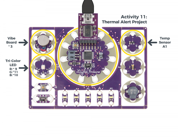
The LilyPad Temperature Sensor outputs voltage depending on the ambient temperature around it. Similar to the light sensor, the temperature sensor has three sew tabs - positive, negative, and signal (S). The temperature sensor board will output specific voltage at set temperatures - 10mV for every degree Celsius (C), with 0 degrees C being set at 0.5V. The current flowing from the board through the signal tab to your LilyPad Arduino Simple can be converted through a formula to degrees in Celsius or Fahrenheit.
What is a Vibration Motor?
The LilyPad Vibe Board is a small motor that shakes when current is applied to it. This board can be used in wearable applications to provide simple haptic feedback.
New Concepts Introduced in This Activity
Multiple Thresholds:
In this activity, we'll use thresholds like the Night-Light project, but assign multiple values associated with hot and cold. We'll use comparison operators to determine if the temperature is within the bounds of each threshold.
Temperature Conversion
The temperature sensor produces an analog voltage representing the temperature near it. In order to get readings in degrees, we'll have to do some math. The voltage output from the sensor is linearly proportional to the Celsius temperature. Once you know the output voltage of the sensor, you can calculate the temperature with this equation:
To convert that reading to Fahrenheit, use this formula:
Next we'll be use Serial Monitor to read the values coming from the sensor and insert the formulas in our code to display the temperature in both Celsius and Fahrenheit.
Example Code
To open the code, go to:
File > Examples > LilyPadDevelopmentBoard_ActivityGuide > LPD_11_ThermalAlert
You can also copy and paste the following code into the Arduino IDE. Hit upload, and see what happens!
language:c
/*
LilyPad Development Board Activity 11: Thermal Alert!
SparkFun Electronics
https://www.sparkfun.com/products/11262

This code reads the input of the temperature sensor and compares it to
a two set thresholds named 'hotAlert' and 'coldAlert'. If temperature is above
the hotAlert threshold, the red channel of the tri-color LED will turn on and the vibe board
will shake. If the temperature falls below the coldAlert threshold, the blue channel of the
tri-color LED will turn on. If the temperature is in the middle of these two thresholds,
the green channel of the tri-color LED will turn on.

Follow the tutorial at:
https://learn.sparkfun.com/tutorials/lilypad-development-board-activity-guide/11-thermal-alert-project

This example is based on Thermal Alert! example in the Digital Sandbox:
https://learn.sparkfun.com/tutorials/digital-sandbox-arduino-companion/12-thermal-alert

This code is released under the MIT License (http://opensource.org/licenses/MIT)

******************************************************************************/

 // Set hot and cold threshold variables to check against. If the temperature reading is above
 // this number in degrees Fahrenheit, we'll turn different LEDs on
 float hotAlert = 80.0;  // 80 degrees Fahrenheit
 float coldAlert = 70.0; // 70 degrees Fahrenheit

// Temperature sensor is connected to A1
 int sensorPin = A1;

// The LEDs in the tri-color LED
int RGB_red = 9;
int RGB_green = 11;
int RGB_blue = 10;

// The vibe board
int motor = 3;

void setup()
{
  // Set the temperature sensor pin as an INPUT:
  pinMode(sensorPin, INPUT);

// Make all of our LED pins outputs:

pinMode(RGB_red, OUTPUT);
pinMode(RGB_green, OUTPUT);
pinMode(RGB_blue, OUTPUT);

pinMode(motor, OUTPUT);

  // Initialize Serial, set the baud rate to 9600 bps.
  Serial.begin(9600);
}

void loop()
{
  // Variable to store raw temperature
  long rawTemp;

  // Variable to store voltage calculation
  float voltage;

  // Variable to store Fahrenheit value
  float fahrenheit;

  // Variable to store Celsius value
  float celsius;

  // Read the raw 0-1023 value of temperature into a variable.
  rawTemp = analogRead(sensorPin);

  // Calculate the voltage, based on that value.
  // Multiply by maximum voltage (4.2V for USB power) and divide by maximum ADC value (1023).
  voltage = rawTemp * (4.2 / 1023.0);
  Serial.print("Voltage: "); // Print voltage reading to serial monitor
  Serial.println(voltage);

  // Calculate the celsius temperature, based on that voltage..
  celsius = (voltage - 0.5) * 100;
  Serial.print("Celsius: "); // Print celcius temp to serial monitor
  Serial.println(celsius);

  // Use a common equation to convert celsius to Fahrenheit. F = C*9/5 + 32.
  fahrenheit = (celsius * 9.0 / 5.0) + 32.0;
  Serial.print("Fahrenheit: "); // Print Fahrenheit temp to serial monitor
  Serial.println(fahrenheit);
  // Print a blank line
  Serial.println();

  // Check the temperature, and turn on the LEDs associated with the hot or cold thresholds
  if (fahrenheit >= hotAlert) // If the temperature rises above the hot threshold:
  {
    digitalWrite(RGB_red, LOW);    // Turn the red LED on
    digitalWrite(RGB_green, HIGH); // Turn the green LED off
    digitalWrite(RGB_blue, HIGH);  // Turn the blue LED off
    digitalWrite(motor, HIGH);     // Turn the motor on to shake as an extra alert
    delay(500);                    // Wait 1/2 second
    digitalWrite(motor, LOW);      // Then turn the motor off
  }
  else if (fahrenheit < coldAlert) // If the temperature falls below the cold threshold:
  {
    digitalWrite(RGB_red, HIGH);   // Turn the red LED off
    digitalWrite(RGB_green, HIGH); // Turn the green LED off
    digitalWrite(RGB_blue, LOW);   // Turn the blue LED on
  }
  else // For all other temperature readings (between hot and cold):
  {
    digitalWrite(RGB_red, HIGH);  // Turn the red LED off
    digitalWrite(RGB_green, LOW); // Turn the green LED on
    digitalWrite(RGB_blue, HIGH); // Turn the blue LED off
  }

  // Wait 1 second between readings
  delay(1000);
}
What You Should See
Open the serial monitor and press your hand on the temperature sensor to see a reading. Your body temperature may not produce a substantial change in the readings from the sensor. Try holding warm or cold objects hear the sensor (be careful with any condensation from a cold object that it does not drip onto the boards). If the reading is above the 'hot' threshold, the red LED on the tri-color LED will light up and the vibe motor will briefly shake. If the reading is below the 'cold' threshold, the blue LED on the tri-color LED will light up. If the reading is between these two thresholds, the green LED on the tri-color will light up.
If you have a certain temperature range in mind, adjust the threshold variables in your code.
Understanding Your Program
Program Overview
- Store the temperature level in the variable
rawTemp. - Print the calculated readings to the Serial Monitor.
- Turn on the LED color based on the hot and cold thresholds. If the temperature is hot, the vibe motor will turn on for a moment to provide feedback.
- Repeat.
Observe Readings in the Serial Monitor:
Open the serial monitor to observe the ambient temperature readings converted from the sensor's voltage output.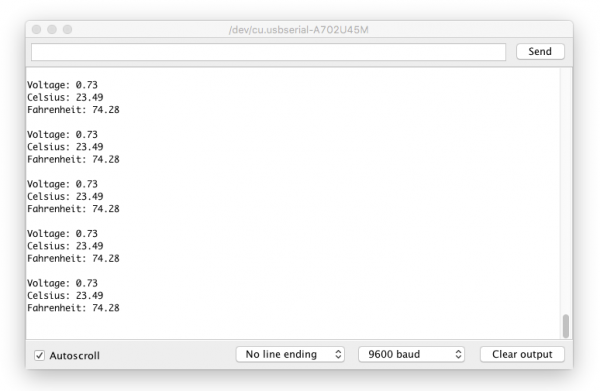
Ways to change the readings: cover the sensor with your hand or breathe on it, move something hot or cold near it.
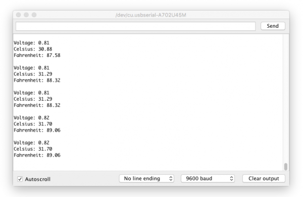
The values on your screen may look different than in this image. The range of readings will depend on your particular surroundings.
If you are having trouble seeing the values, double check that 9600 baud is selected in the dropdown menu at the bottom right of the window and the auto scroll option is checked.
Code to Note
| Code | Description |
|---|---|
float hotAlert = 80.0; float coldAlert = 70.0;
|
Set Thresholds:In this program, two thresholds are set for hot and cold readings. Adjust these as needed for the interaction you would like in your project. |
long rawTemp;float voltage;float fahrenheit;float celsius; |
Variable Data Types:Up until this point, most of the variables in the examples have been integers (int). In this program, we'll use a long to store the raw temperature readings and floating point (float), which is a number with a decimal point.
Learn more about floating point numbers on the Arduino Reference site. |
rawTemp = analogRead(sensorPin);
voltage = rawTemp * (4.2 / 1023.0);Serial.print("Voltage: ");Serial.println(voltage);
|
Storing Sensor Reading:First, the program stores the sensor reading into a variable calledrawTemp to use in the conversion formulas. Since we know from the sensor's datasheet that voltage being read from the sensor has a relationship to temperature, we can use the voltage = rawTemp * (4.2 / 1023.0) formula to interpret the analog to digital converter's output and determine the voltage.
|
celsius = (voltage - 0.5) * 100;Serial.print("Celsius: ");Serial.println(celsius);
float fahrenheit = (celsius * 9.0 / 5.0) + 32.0;Serial.print("Fahrenheit: ");Serial.println(fahrenheit);Serial.println();
|
Conversion Formulas:Next, the code uses the voltage to translate to temperature in Celsius. Then a standard formula for converting Celsius to Fahrenheit (F = C*9/5 + 32). The program also prints all the variables to the serial monitor so you can observe them as they change. This is a great way to see the room's ambient temperature using the development board and adjust the temperature thresholds for your alerts as needed. |
if (fahrenheit >= hotAlert) |
Compare Readings to Thresholds:A set ofif statements check if the fahrenheit variable is above, below, or between the hot & cold thresholds. As a result, the LilyPad Arduino Simple turns the red, green, and blue LEDs on depending on which threshold the variable is within. In the first if statement, there is also code to turn on the LilyPad Vibe Board to shake if things are too hot.Note that the second check uses an else if instead of just an if statement to check the temperature. This is because the temperature sensor cannot be hot and cold at the same time. Using three individual if statements would be inefficient since the Arduino would check each condition. It is not recommended in this case since the sensor will only be able to provide one temperature value at a time. Since all three condition statements cannot be true at the same time, the test is mutually exclusive and requires each test to be grouped together.
Learn more about if/else statements on the Arduino Reference site. |
Coding Challenges
Can you change the code so that the buzzer sounds different audio alerts depending on the temperature?
Can you use the row of white LEDs as a bar graph to get more specific visual indication of the temperature variations?
Try creating a 'quiet' mode by using the switch to silence the vibe board alarm and just display on the tri-color LED.
Troubleshooting
As you begin to edit the example code and write your own programs, you may experience some error messages. This section highlights a few common issues and solutions as you work on your Arduino code.
At the bottom of the Arduino IDE is section with a black background. This is the Debug Window - if something unexpected or incorrect happens and Arduino can't communicate to your LilyPad Arduino Simple or run the code you've written, an error message will display here. The top of the section will turn orange and a "Copy Error Messages" button will display.
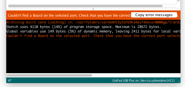
Common Error Messages
Error: "Couldn't find a Board on the selected port"
- Check that you have the correct port selected.
- Check that LilyPad Arduino is selected in the board menu, NOT LilyPad Arduino USB.
- Try pressing the board's reset button after initiating the upload.
- Check that the LilyPad Arduino Simple is switched to ON.
- Check that the USB cable is correctly connected to your computer and LilyPad FTDI board.
- Check that the FTDI board is correctly connected to the LilyPad Arduino Simple.
- Check that the USB cable is not a 'power only' cable.
Error: "Expected ';' before"
This error happens when there is a missing ; at the end of a statement. Arduino will highlight the line in red in the code window and print a line number in the code around where the error occurred to help you identify where you need to fix something. You can turn on line numbering in Arduino > Preferences.
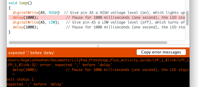
; after digitalWrite(A5, HIGH) caused the error. Error: "'variable' was not declared in this scope"
Scope errors can happen for a variety of reasons, here are some common things to check:
- Variable mismatch (spelling, capitalization, spacing differences) when trying to use a variable you have declared in another part of your program
- Variable was not declared with a type before use.
- Variable was declared within a function and not globally and is trying to be used outside of that function.
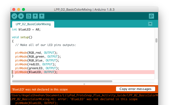
blueLED was mistyped as BlueLED. Arduino did not recognize BlueLED, while it may look similar enough to you, Arduino is case sensitive. Error: "Expected '}' at end of input"
As you copy and paste to move pieces of your code around or work with nested functions, your code will accumulate a lot of curly brackets. To keep track of nested functions in the example code, we use indented formatting. Each new nested layer of function is indented an addition time to visually organize the code. If one of the opening { or closing } is accidentally deleted or not added, you will get an error.
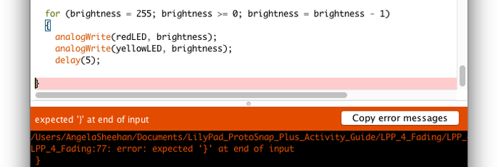
This error happened because the closing bracket for the for() loop is missing. This can be initially misleading, as Arduino highlighted a closing bracket - this one belongs to the loop. The space above it is where Arduino expected a match for the opening bracket of the for() loop - highlighted in blue.
Keeping Track of Brackets
Arduino has a handy feature built in that highlights the matching curly bracket if you place your cursor after one. You can use this to quickly check that there are no brackets left behind.
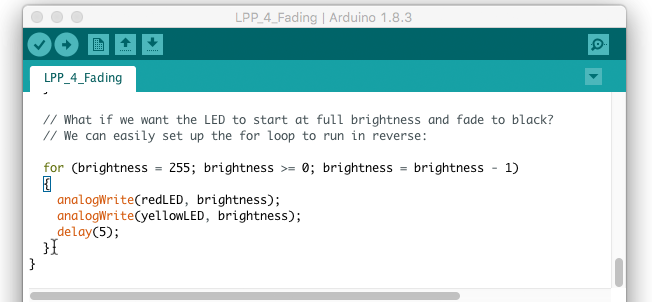
for () loop highlights its matching opening bracket with a blue outline. Depending on the Arduino IDE version that you have installed, you may also be able to view the function that was associated with the bracket if it is out of frame. In this example, we were using Arduino IDE v1.8.3.
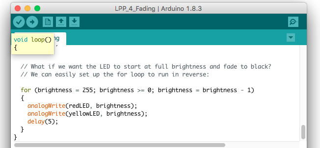
loop() function highlights the function and bracket when it is out of frame. Semantics Error and Debugging
Why is my code not working even though it compiles?
This sounds like a pretty general question, but it's likely a semantic error. While the code is able to compile and is free from syntax errors, the code might not be written to do what you intended. Assuming the hardware connections and boards are good, it is possible that:
- A pin or variable was not initialized correctly.
- A variable was not calculated and saved correctly.
- The wrong variable is printing to the Serial Monitor.
- You are using values outside of an array[].
- There is a baud rate mismatch.
- A
delay()function is preventing a certain line from executing fast enough. - The sequence of code is not executed properly.
The list of reasons why this may be happening can go on depending on the complexity of the project. The simplest method of debugging can be turning on an LED when we reach a certain part of the code. However, the best method of troubleshooting Arduino code is to try to step through using the serial.print() function to debug. If used correctly, the function is more flexible and can indicate that we have entered a line of code.
Maybe you want to print "I entered this function" to the Serial Monitor after pressing a button or when a sensor reaches a certain value. The serial.print() function can also be used to inspect variables in order to know what to expect from a sensor's output range. The function can also be used to verify calculations. Other environments allow you to step through the code to simulate what may happen without the need for serial.print().
Resources and Going Further
For more information about the LilyPad Development Board, check out the resources below:
- Schematic (PDF)
- Eagle Files (ZIP)
- Getting Started Guide
- LilyPad Portal Ecosystem
- Default Example Arduino Sketch
- LilyPad Development Board GitHub Repository
- GitHub Code Repository
Here are some additional LilyPad boards that can be combined with the LilyPad Development Board and project ideas:
LilyPad Pixel Board Hookup Guide
LilyPad Reed Switch Hookup Guide
LilyPad Safety Scarf
Here are some resources to help you plan a project with the LilyPad Development Board:
Insulation Techniques for e-Textiles
Planning a Wearable Electronics Project
Powering LilyPad LED Projects
LilyPad Basics: E-Sewing
For educators looking for classroom activities with the LilyPad Development Board and e-textiles, try looking at our education resources: